SIMULATION OF OIL-WATER TWO PHASE FLOW AND SEPARATION BEHAVIORS IN COMBINED T JUNCTIONS*
2012-08-22CHENJianleiHELiminLUOXiaomingBAIHaitaoWEIYanhai
CHEN Jian-lei, HE Li-min, LUO Xiao-ming, BAI Hai-tao, WEI Yan-hai
College of Pipeline and Civil Engineering, China University of Petroleum (East China), Qingdao 266555, China, E-mail: chenxiqiji111@163.com
(Received February 25, 2012, Revised June 16, 2012)
SIMULATION OF OIL-WATER TWO PHASE FLOW AND SEPARATION BEHAVIORS IN COMBINED T JUNCTIONS*
CHEN Jian-lei, HE Li-min, LUO Xiao-ming, BAI Hai-tao, WEI Yan-hai
College of Pipeline and Civil Engineering, China University of Petroleum (East China), Qingdao 266555, China, E-mail: chenxiqiji111@163.com
(Received February 25, 2012, Revised June 16, 2012)
The combined T junctions used for the oil-water separation have the advantages of compactness in structure, consistency in effects and economy in cost. The mixture kε- turbulence model and the Eulerian multi-fluid model are used to simulate the flow and phase distribution in the combined T junctions. The effects of structural parameters such as the branched pipe interval and height on the flow distribution and the separation behaviors are studied. The results show that the combined T junctions under fixed inlet and outlet boundary conditions form a single hydraulic equilibrium system in which the fluid energy distributes freely till a balance is achieved. The split-flow promotes the separation of the immiscible oil and the water. The separation efficiency increases with the increase of the branched pipe interval and changes slightly with the increase of the branched pipe height. The structural change of the combined T junctions may change the flow direction in the branched pipes. Simulation results can provide some guidance for the design of the combined T junctions as one kind of oil-water separator.
T junction, oil-water separation, CFD, phase distribution
Introduction
Since it was discovered that the gas-liquid two phases distribute unevenly in two branch outlets while flowing through a single T junction in the 1960s, extensive theoretical and experimental researches were carried out about the T junction as a preliminary separator[1,2]. Considering the complexities of the gasliquid flow patterns and the diversities of T junction structures, experiments are considered as the main means for the T junction study, and on the other hand, the theoretical models find limited applications due to the lack of required boundary conditions and relational equations on the phase interface. Experimental studies were focused on the effects of both operational conditions and T junction structures. The gas-liquid flow patterns such as the stratified flow[3,4], the slugflow[5]and the annular flow[6], are the primary operational conditions that affect the gas-liquid split-flow in the T junction. Generally speaking, the separation effect is great in the stratified flow and is not great in the slug flow and the annular flow. The effects of T junction structures on the separation mainly concern the diameter ratio of the branched pipe to the main pipe, the branched pipe layouts and the angles[7,8]. Until recently, attentions began to focus on the liquidliquid separation in the T junction. Yang et al.[9]studied the kerosene-water separation experimentally in a single T junction with a horizontal main pipe and a vertical upward branched pipe, and it is indicated that the phase separation is highly effective under the conditions that the two-phase flow patterns approaching the T junction inlet are the stratified flow and the volume flow rate ratio of the fluid in the vertical upward branched pipe to that in the horizontal main pipe is close to the inlet kerosene volume fraction. Subsequently, the research of the liquid-liquid separation is extended to the combined T junctions and a patent is applied. In China, the studies of the combined T junctions were focused on the single-phase flow distributions in pipe networks of water supply and drainage in geographical regions. But the research of the combi-ned T junctions for an intensive and compact oil-water separator is still in the initial stage. Zheng et al.[10]took the combined T junctions as one of the core units for the gas-liquid and partial oil-water separation during the development of a combined gas/oil/water separator, with a good result. Wang et al.[11,12]studied the single T junction and the combined T junctions using both the methods of experiments and computational fluid dynamics, and it was indicated that the single T junction plays an important role in the oilwater separation, however, the separation efficiency is affected sensitively by the mixture velocities, the volume fractions and the flow patterns. On the other hand, a high separation efficiency could be achieved in a wider operation region when using the combined T junctions.
However, studies were mainly focused on the gas-liquid two-phase flow and the separation in a single T junction, not so much on the liquid-liquid separation in combined T junctions. So far, the flow behaviors in each branched pipe of combined T junctions and the effect of the flow distribution on the oil-water separation were not much studied[12]. Experimental studies were restricted due to the limitations in operational conditions, funds and periods, so that the conclusions drawn from experiments lack the universal nature. This paper analyzes the influences of branched pipe structures on the oil-water flow and the phase distribution characteristics using Fluent, a commercial software of CFD, to provide a design basis of the combined T junctions for oil-water separators.
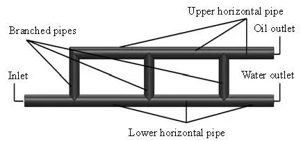
Fig.1 Schematic diagram of combined T junctions
1. Numerical simulation
1.1 Geometrical model and meshing
The geometrical model of the combined T junctions with three branched pipes is shown in Fig.1. The oil-water mixtures enter the combined T junctions and are split in the lower horizontal pipe and the upward vertical branched pipes. Due to the density difference, most of the oil stays in the upper part of the pipe section. The rich oil fluid flows through the branched pipes to the upper horizontal pipe and outflows from the oil outlet, meanwhile the rest of fluid with rich water flows through the lower horizontal pipe to the water outlet. The mesh generation of the fluid computational domain is performed by the Gambit which divides the whole geometry into several blocks and meshes each block separately. In view of the flow complexity in the junction points and in order to capture the flow and phase distribution features, the compact tetrahedral meshes and the pentahedral pyramid meshes are adopted in both the junction points and the branched pipes, while the unstructured hexahedral meshes produced by the Cooper method are used in the upper and lower horizontal pipes. The unstructured quadrilateral meshes are used in the interfaces between different blocks.
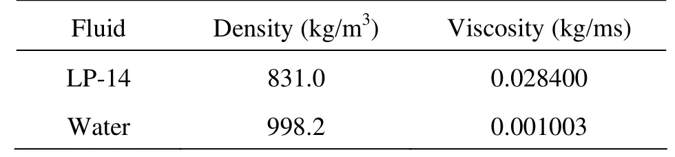
Table 1 Physical properties of oil and water (20oC)
1.2 Boundary conditions
The velocity inlet boundary is adopted. The oilwater flow regime map drawn by Trallero based on experiments has a good credibility, and were widely quoted, such as Wang[12], Xu et al.[13], Yang and Azzopardi[14]. Both the working medium physical properties listed in Table 1 and the pipe diameter used in this paper are similar to those used in Trallero’s experiments, so we choose the ST&MI flow pattern and the corresponding oil-water apparent velocities from the Trallero’s flow regime map as the inlet boundary conditions. The outflow boundary[15,16]is adopted on two outlets. The split ratio is defined as the ratio of the fluid volume flow rate in the upper outlet to that in the mixture inlet, and is set accordingly. During the simulation, the split ratio is equal to the inlet oil volume fraction, because it is the theoretical optimal split ratio of a complete separation[9]. The wall no-slip boundary is adopted on the wall boundary of the computational domain.
1.3 Model setup
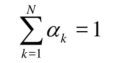
In the Eulerian multi-fluid model, the two phases are regarded as interpenetratable continuous mediums and the phase coupling can be considered adequately. This model is widely used in the field of multiphase flow and separation[17,18]. Wang et al.[11]described the model in detail, as is used in this paper. The governing equations of the Eulerian multi-fluid model are as follows.
According to the mass conservation law, the continuity equation is
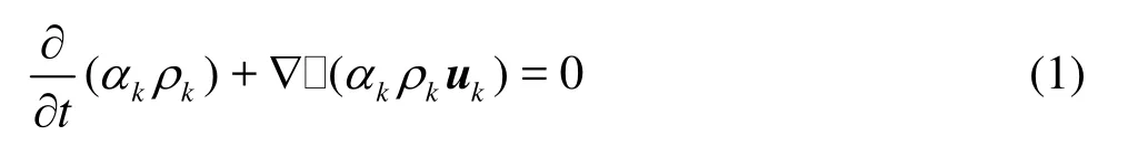
where α is the phase volume fraction, ρ is the phase density and u is the phase velocity
The conservation equation for the momentum can be expressed by
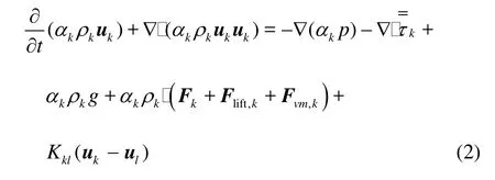
wherep is the static pressure,is the stress-strain tensor, g is the acceleration of gravity, F is the external volume force, Fliftis the lift force,Fvmis the virtue mass force and Kklis the interphase exchange coefficient
The dispersed oil phase particle diameter used in this paper is 0.0004 m, which is relatively large, so the lift force must be taken into account

The exchange coefficient Kklfor the oil/water two-phase flow can be written in the following general form
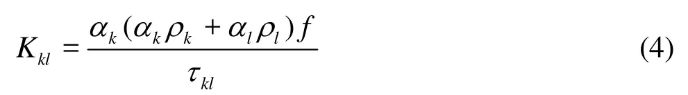
whereklτ is the particulate relaxation time and f is the drag function, defined as
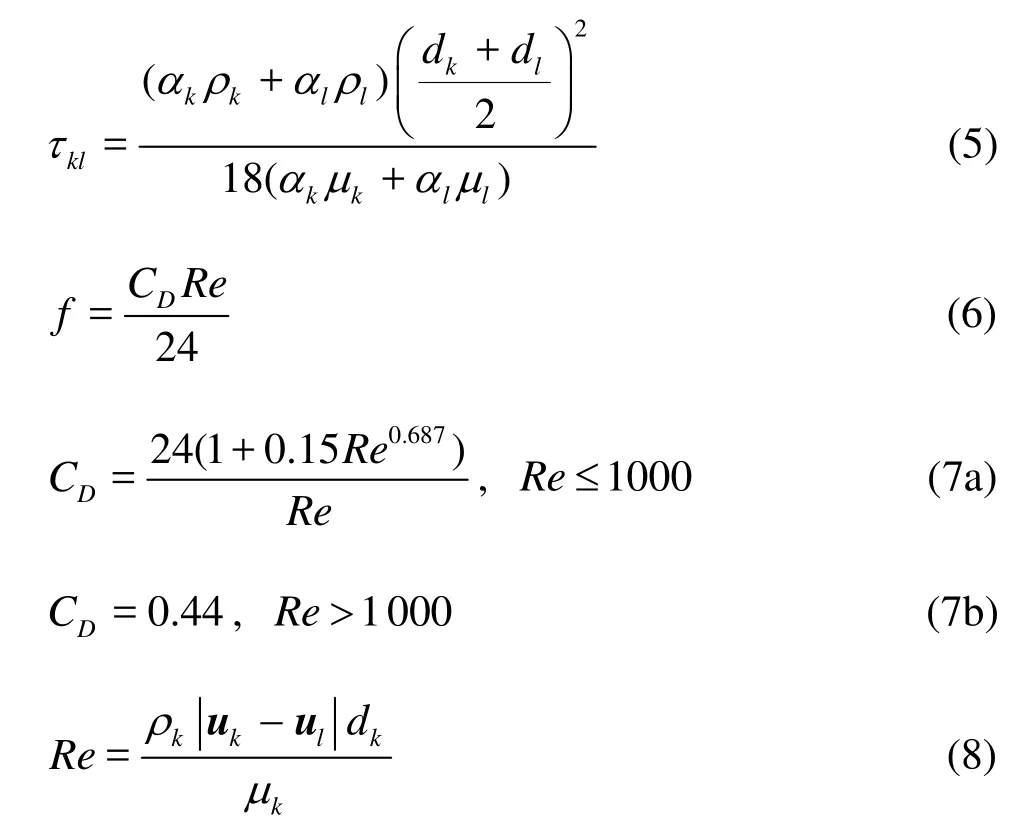
where d is the part icle size, μ is the kinetic viscosity,CDis the drag coefficient and Re is the Reynolds number.
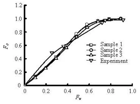
Fig.2 Com parison between numerical simulations and Pandey’s experiments
The flow pattern simulated in this paper is the ST and MI, which is close to a stratified flow, the mixture k-ε turbulence model can be used to capture the major features of the turbulent flow, and k andε equations are as follows:
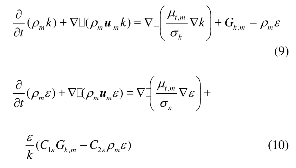
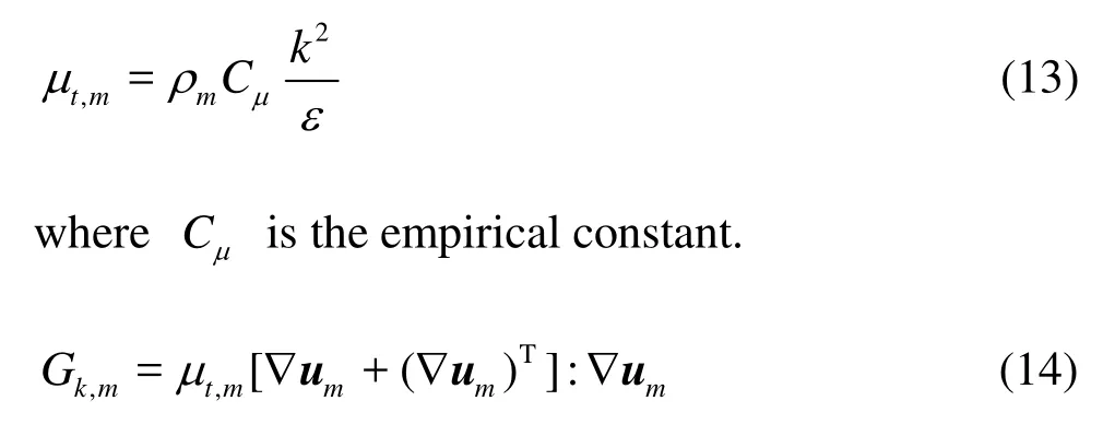
where k is the turbul ent kinetic energy, ε is the turb ulent dissipation rate,ρmis the mixturedensity, umis the mixture velocity, μt,mis the turbulent viscosity, Gk,mis the production of turbulence kinetic energy, C1ε, C2εare the modelconstants are defined as:
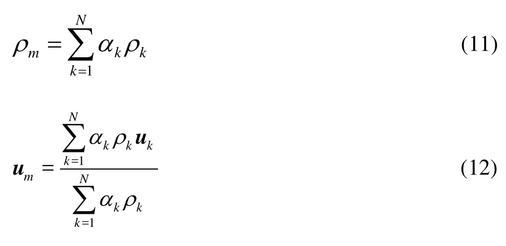
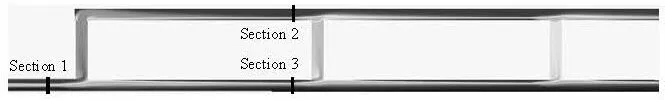
Fig.3 Phase distribution along the longitudinal symmetry plane of combined T junctions
The turbulent viscosity μtand the production o f the turbulence kinetic energy Gk,mcan be computed from
In order to verify the above model and the grid independence, the oil-water two phase flow inside a horizontal T junction is numericallysimulated and three different mesh densities are used, 315 384 cells are adopted in sample 1, 159 990 and 90 366 cells are adopted in sample 2 and sample 3, respectively. The results are compared with the experimental data obtained by Pandey et al.[19]. Figure 2 shows that the simulation results agree well with the experimental data and the mesh densities do not have much influence on the results. The Eulerian multi-fluid model and the mixture kε- turbulence model can satisfy the need of the simulation of the combined T junctions completely.
2. General analysis on flow and separation properties
The c ombined T junctions considered in this section consist of three branched pipes and the diameter of all the pipes is set as D=0.04m . The height and the interval of branched pipes are H=6D, and L=20D. The operation conditions are: the inlet mixture velocity is 0.5 m/s, the oil volume fraction is 40% and the split ratio is 0.4.
Figure 3 presents the oil phase distribution along the longitudinal symmetry plane of thecombined T junctions. It is clearly shown that a split-flow is generated when the oil-water flows through the three junction points in the lower horizontal pipe. The oil phase in the upper part of the lower horizontal pipe firstly flows through the branched pipes into the upper horizontal pipe, which indicates that such structures can play a role in promoting the oil-water separation.
The combined T junctions can be taken as a complex pipe system consisting of numerous branched pipes and collecting pipes. In the condition of the fixed inlet/outlet boundaries and the steady flow, the energy of the fluid can distribute automatically in each branched pipes,till a balance is reached, from which the distributions of the volume flow rates and the flow directions can also be determined. At this point, we will analyze the fluid diversion in the branched pipes simply by the total flow Bernoulli equation ofthe actual fluid. As shown in Fig.3, the pipe between cross sections 1-2 and 1-3 can be assumed to be a single branched pipe with an energy distribution that the sum of the total mechanical energy and the energy loss per unit volume of the fluid in each branched pipe is equal to the total mechanical energy per unit volume of the fluid before the junction point. The total flow Bernoulli equation for both 1-2 and 1-3 cross sections for unit volume of the fluid may be expressed as:
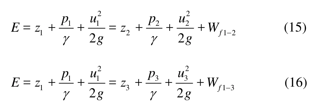
where E is the total mechanical energy, z is the potential head, p is the static pressure,γis the unit weight, uis the flow velocity, W is the friction loss,Wf1-2and Wf1-3represent the friction lossper unit volume of the fluid from cross Section 1 tocross Section 2 and to cross Section 3, respectively, which are the sum of the friction loss along the way and the local loss
where λ, ξarethe drag coefficient, L is the pipe length and D is the internal diameter of pipe.
As for a determinate closed system, if the hydraulic friction loss per unit volume of the fluid from Section 1 to Section 2 is larger than that to Section 3, and the total mechanical energy at Section 3 is high enough to overcome the potential energy caused by the vertical branched pipe, then, the fluid in the2nd junction point can continue to split upward. Similarly, the fluid in the 3rd junction point can alsocontinue to split upward if the condition is like that at the 2nd junction point. In general, the split-flow in the branched pipes reflects a balance between the energy supply and the loss in a closed hydraulic system.
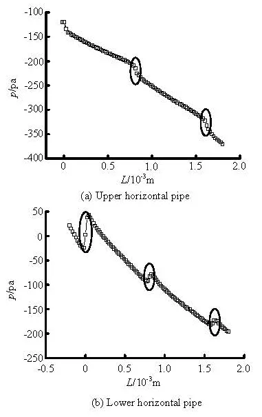
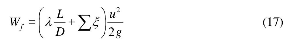
Fig.4Static pressure distribution in pipe axial center lines
Figure 4 illustrates the static pressure distribution inthe upper and lower horizontal pipe’s axialcenter lines. It is clearly seen that the static pressure distributionsees a decreasing trend along the flow direction due to the friction drag. The step up and the stepdown of the static pressure occur around the lowerand upper junction points (marked with ellipses),respectively. This means that the function of the flowdiversion and collection in the junction points leadsto a mutual transformation between the pressure energy andthe kinetic energy. Because we have the same pipe diameter, the split-flow up in the lower horizontal pipe decreases the flow rate in the pipe, consequently, the specific kinetic energy also decreases and a step up of the static pressure occurs. The flow collection in the upper junction points increases the flow rate, as a result, the specific kinetic energy increases and a step down of the static pressure happens.
From the static pressure distribution in the lower horizontal pipe, we can also see that the variation range of the static pressure in the junction points decreases along the flow direction. This means that the transformation range of the kinetic energy and the pressure energy becomes smaller and smaller, the volume flow rate distributed in the serial branched pipes gets smaller as well, as shown in Fig.5.
Fig.5 Volume flow rate in different branched pipes
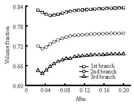
Fig.6 Oil phase concentration distribution in different branched pipe sections
The split-flow effect of the combined T junctions not only can increase the amount of oil in the upper part of the lower horizontal pipe sectionaccessible to t he branched pipes, but also can disintegrate the oilwater mixture velocity to provide a buffer time for the gravity settlement slippage. Looking back to Fig.3, the distributions of the oil and the water in the branched pipes are uneven due to the effect of the disturbance and the turbulence. With the development of the flow in the branchedpipes, the disturbance and the turbulence at the junction points are reduced, as a result, the effect of the gravity and the density difference make the oil and water settlement delayed. The more upward the branched pipes are, the more homogeneous the oil distribution and the larger the average oil concentration will be obtained. Figure 6 shows the average oil concentration of 22 equidistant cross sections in each branched pipe, where the disturbance near the junction points makes the oil phase concentration distribution different in 3 branched pipes. The oil phase concentration increases steadily when the flow is far away from the disturbance area.
Through a general analysis of the split-flow and the separation behaviors in the combined T junctions we can see that the combined T junctions with fixed inlet and outlet boundary conditions form a single hydraulic equilibrium system in which the fluid energy distributes freely till a balance is reached. Inaddition, the function of the split-flow in the combined T junctions promotes the separation of the immiscible oil and the water.
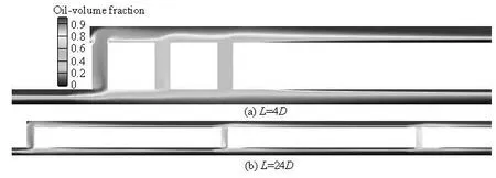
Fig.7 Oil phase distribution along the longitudinal symmetry plane of combined T junctions with different branched pipe intervals
3. Effects of branched pipe intervals
In order to see the effects of the branched pipe intervals on the flow and separation behaviors, 7 combined T junctions with equal branched pipe interval of different lengths, namely L=4D,8D, 12D, 16D, 20D, 24Dand 28D, respectively, areanalyzed. The height of all branched pipes is setas 4D, the oper ational conditions are: the mixture velocity is 0.5 m/s, the oil volume fraction is 40% and the split ratio is 0.4.
3.1 Phase distribution characteristics
Figure 7 shows two representative oil phase concentration distributions along the longitudinal symmetry plane of 7 combined T junctions with equal branched pipe interval of different lengths. It can be seen that the ST and MI flow pattern exists before the oilwater mixtures enter the first junctionpoint. In order to ensure the full development of the flow, the ratio of the pipe length to the diameter before the first junction point is set to be 50:1. From the oil phase distributions in the combined T junctions with branched pipe intervals of 4D and 8D, it can be seen that the local disturbance caused by the junction points makes the oil and water distribution unstable because of small branched pipe intervals. Before the oil and water enter the 2nd and 3rd junction points, the oil and water distributions in the lower horizontal pipe are under miscellaneous states, so that the oil droplets can not be formed in the effective settlement aggregation while flowing along the lower horizontal pipe, and the effects of the gravity and the oil-water phase momentum difference on the phase separation are not witnessed. As a result, we have poor separation effects in the next two junction points, namely, the whole separation efficiency of the combined T junctions is low. From the beginning of the combined T junctions with the interval of 12D, the branched pipe intervals are enlarged. After the disturbance of the prior junction point and before reaching the next junction point, the oil and waterhave more full settlement buffer time toprovide abetter prerequisite for the next split-flow separation. Withthe increase of the branched pipe intervals, the oil-water flow is more stable. The oil-water separation efficiency by the discriminate method can be expressedas
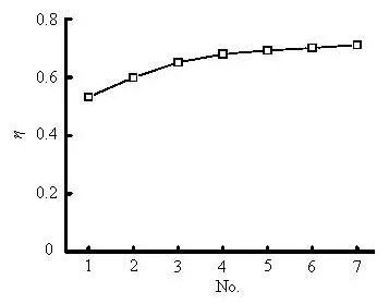
Fig.8 Sep aration efficiency of 7 combined T junctions atVm= 0.5 m/s
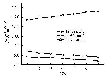
Fig.9Volume flow rate distributions in 3 branched pipes
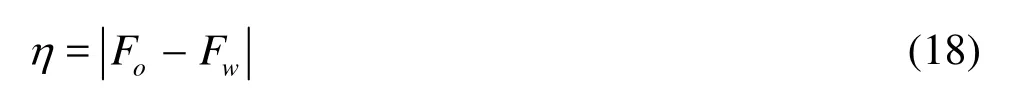
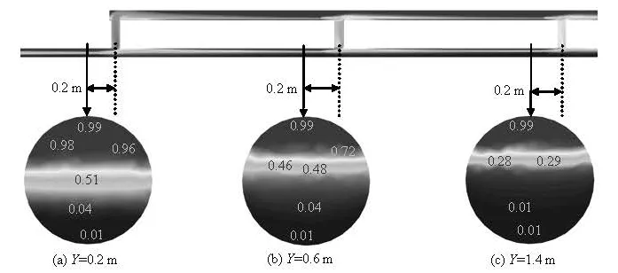
Fig.10 Phase di stribution in lower horizontal pipe sections
whereoF is the ratio of the oil phase mass flow rate in the upper horizontal pipe outlet to that in the mixed inlet, Fwis the ratio of the water phase mass flow rate in the upper horizontal pipe outlet to that in the mixed inlet. From the calculation formula we can see that the separation efficiency can reach 100% only when one phase is completely taken off from the upper horizontal pipe and without another phase being taken off. On the other hand, the separation efficiency is zero when two phases distribute uniformly. The separation efficiencies of above 7 combined T junctions are shown in Fig.8.
Figure 8 indicates that the separation efficiency increases with the increase of branched pipe intervals. But when the interval is above than some value (No. 5 in the figure, for example), the separation efficiency’s increase is slight, due to rather stable distribution of the oil-water two phases inthe lower horizontal pipe, therefore, in the practical application of combined T junctions as an oil-water separator, we should select an appropriate branched pipe interval to balance the relationship between the space requirement and the separation efficiency.
The increase of the branched pipe interval can improve the separation efficiency because the oilwater can flow in a more stable way in the horizontal pipes between the branched pipes and would have a larger settlement surface as well as a more sufficient settling time. In addition, the increase of the branched pipeinterval can also make the volume flow rate distribution change in the branched pipes, which would also affect the separation efficiency.
3.2 Flow distribution characteristics in branched pipes
In addition to the effects of the oil-water density difference and the split-flow in the branched pipes, the oil concentration and the volume flow rate distributions in the branched pipes, which are related with the oil phase contents in the upper and lower horizontal pipes, are also important factors for the oil-water separation.
Figure 9 shows the volume flow rate distributions in 3 branched pipes of 7 combined Tjunctions. With the increase of the branched pipe interval,the volume flow rate increases continuously inthe first branched pipe and decreases continuously in the rest two branched pipes. For the same combined T junctions, the volume flow rate in the forward branched pipes is larger than that in the backward branched pipes.
F ig.11 Oil concentration distribution in 3 branched pipes
Figure 10 shows the oil phase distributionin the lower horizontal pipe sections 0.2 m ahead of 3 junc tion points with the interval of20D. Theoil-water mixtures flow through each junction point in the ST and MI flow pattern, due to the split-flow effect of the j unction points, the thickness of the oil phase enrichment layer and the oil-water mixing layer reduces, but t he thickness of the water phase enrichment layerincreases. The oil and the water become layered dueto t he density difference, during the flow process, theoil and the water in the lower horizontal pipe section flow in turn from top to bottom into the branched pipes. For eachpipe section shown in Fig.10, when the volume flowrate in the branched pipe is relatively small, only the oil phase enrichment layer at the upper part of the lower horizontal pipe flows into thebranched pipe, so the oil phase average concentration in the branched pipe is relatively high. With the increase of the volume flow rate in the branched pipe, the oil-water mixing layer at the middle part of the lower horizontalpipe also begins to enter the branched pipe, so that the total oil phase average concentration becomes small, with the further increase of the volume flow rate, the water enrichment layer at the lower part of the horizontal pipe enters the branched pipes as well and leads to a lower oil phase concentration there. The decrease of the volume flow rate in the 2nd and 3rd branched pipes makes the oil phase average concentration in them increase. Though the oil phase average concentration in the 1st branched pipe decreases due to the high volume flow rate, it is still at a very high level as compared with those in the 2nd and 3rd branched pipes.
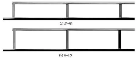
Fig.12 Oil phase dist ribution along the longitudinal symmetry plane of combined T junctions with different branched pipe heights
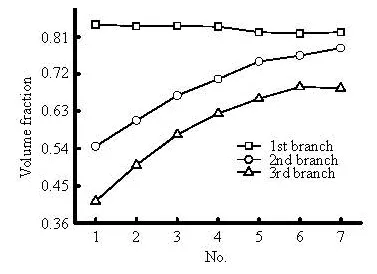
Figure 11 shows the oil phase average concentration in 3 branched pipes of 7 combined T junctions. The oil concentration in the latter two branched pipes increases gradually with the increase of the branched pipe interval and that in the 1st branched pipe decreases instead. The high volume flow rate in the 1st branched pipe is caused by the increase of the branched pipeinterval, as a result, the mass oil phase enters the 1st branched pipe and accompanies the mass water phase as well, and meanwhile, the lower volume flow rate in the 2nd and 3rd branched pipes causes the increase of the oil phase average concentration. As a summary, the more stable flow between the branched pipes and the greater oil phase contents in the forward branched pipes are two primary reasons for the combined T junctions with larger branched pipe interval to have a high separation efficiency.
4. The effects of branched pipe height
To see the effects of the branched pipe height, we consider combined T junctions with the interval of 20D and the branched pipe heights of 4D, 6D, 8D, 10D, 12D and 14D.
4.1 Phase distribution characteristics analysis
Figure 12 illustrates two representative oil phase concentration distributions along the longitudinal symmetry plane of the combined Tjunctions with different branched pipe heights. From the combined T junctions with the heights of 4D and 6Dwe can see that the change of the oil phasedistribution is not great and the oil-water splits upward, the branched pipes see still good separation effects. From the combined T junctions with the heightsof 8D-14D, the oil phase distribution changes greatly. It is clearly seen from the cloud picture display that the oil concentration in the corresponding branched pipes decreases, especially, in the 3rd branched pipe with high water concentration. At this moment, the flowdistribution characteristics can explain this phenomenon.
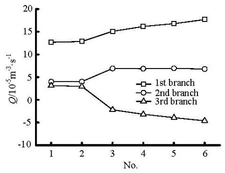
Fig.13 Volume flow rate distributions in different combined T junctions at Vm=0.5m/s
4.2 Flow distribution characteristics in branched pipes
Figure 13 shows the volume flow rate distributions in3 branched pipes of different combined T junctions.The flow direction in 3 branched pipes is no longer consistent with the trend followed by the increaseof the branched pipe heights (from the heightof 8D upwards). When the fluid in the lowerhorizontal pipeflows through the 3rd junction point, themechanical energy of the fluid can not overcome thepotential energy related with the branched pipe height to lift it up, so that the flow direction reverses in the 3rdbranc hed pipe.
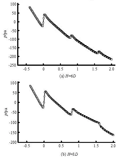
Fig.14 Static pressure distributions in lower horizontal pipe axial center lines
Figure 14 shows two representative static pressure distributions in the lower horizontal pipe axial center lines of the combined T junctions with different branched pipe heights. As can be seen, the staticpressure step up can be seen in 3 junction points of the combined T junctions with branched pipe heightsof 4D and 6D, however, the static pressure step up can be seen only in the 1st and 2nd branched points and the step down is seen in the 3rd branched pointin the combined T junctions with branched pipe heights of 8D-14D. The static pressure step up means that the flow splits upward in the junction point and the volume flow rate decreases, while the static pressure stepdo wn means thatthe flow converges in the junctionpoint and the volume flow rate increases. In Fig.13, the oil-water flows downward along the 3rd branched pipe and the flow direction is opposite to that in the first two branched pipes with height of 8D or greater. In the combined T junctions with an identical flow direction, the volume flow rate in 3 branched pipes is essentially consistent, in those structures with the reversed flow direction, the volume flow rate increases steadily in the 1st branched pipe, changes a little in the 2nd branched pipe and increases in the oppositedirection in the 3rd branched pipe with the increase of the branched pipe height.
The volume flow rate in 3 branched pipes is essentially consistent in structures with an identical flow direction, so that the separation efficiency is in general constant. In structures with the reversed flow direction, the increase of the volume flow rate in the 1st branched pipe enlarges the overall contribution to the separation efficiency due to the higher oil concentration there, the volume flow rate in the 2nd branched pipe changes slightly, thus the oil content there changes slightly as well, the rich oil phase flows downward in the 3rd branched pipe and offsets the effect of increasing the separation efficiency by the 1st branched pipe. As a result, under the conditions of the simulation study, due to thecombined action of 3 branched pipes, the total separation effici ency in all combine d T junctions with different branched pipe heights changes only a little and is listed in Table 2.
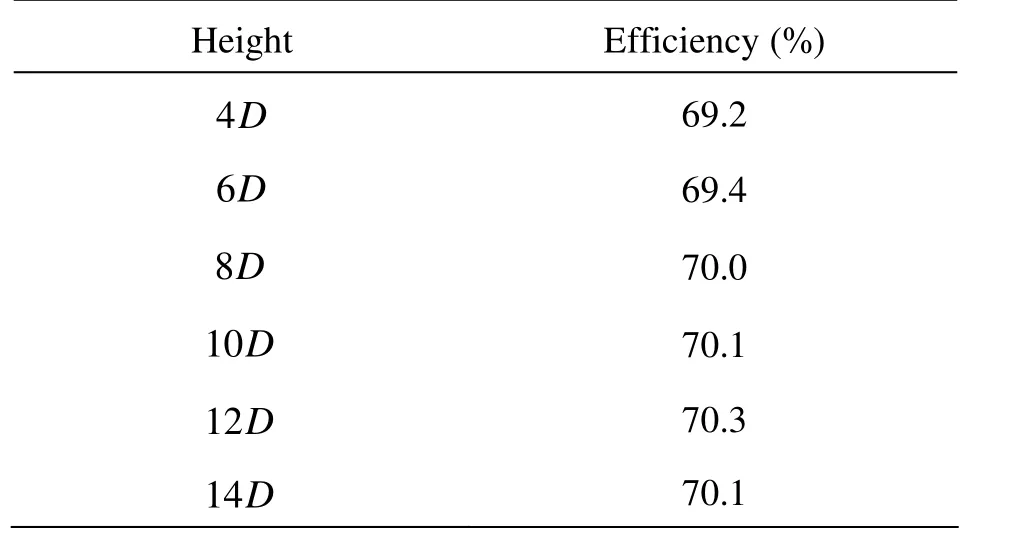
Table 2 Separation efficiency of combined T junctions with different branched pipes heights
5. Conclusions
(1) The combined T junctions under fixed inlet and outlet boundary conditions form a single hydraulic equilibrium system in which the fluid energy distributes freely till a balance is reached.The function of the split-flow in the combined T junctions promotes the separation of the immiscible oil and the water.
(2) The oil-water separation efficiency increases with the increase of the branched pipe interval in the ST and MI flowpattern. The increaseof the branched pipe interval makesthe oil and water settlement stable and changes the volume flow rate distributions in the branched pipes.
(3) Under the conditions of the simulation study, the change of the branched pipe height does not have an observable impact on the separation efficiency. However, it can reverse the flow direction in the branched pipes. In the combined T junctions with no reversed flow direction, the volume flow rate distributions in the branched pipes change only a little with the increase of the branched pipe height, so the separation efficiency changes only a little as well. In the combined T junctions with a reversed flow direction, due to the offset effects of the volume flow rate distributions in three branched pipes, the overall separation efficiency changes only a little.
References
[1] WREN E., AZZOPARDI B. J. The phase separation capabilities of two T-junctions placed in series[J]. Chemical Engineering Research and Design, 2004, 82(3): 364-371.
[2] MARGARIS DIONISSIOS P. T-junction separation modelling in gas-liquid two-phase flow[J]. Chemical Engineering and Processing: Process Intensification, 2007, 46(2): 150-158.
[3] REA S., AZZOPARDI B. J. The split of horizontal stratified flow at a large diameter T-junction[J]. Chemical Engineering Research and Design, 2001, 79(4): 470- 476.
[4] DAS G., DAS P. K. and AZZOPARDI B. J. The split of stratified gas-liquid flow at a small diameter T-junction[J]. International Journal of Multiphase Flow, 2005, 31(4): 514-528.
[5] WRENE., BAKER G. and AZZOPARDI B. J. et al. Slug flow in small diameter pipes and T-junctions[J]. Experimental Thermal and Fluid Science, 2005, 29(8): 893-899.
[6]STACEY T., AZZOPARDI B. J. and CONTE G. The split of annular two-phase flow at a small diameter T-junction[J]. International Journal of Multiphase Flow, 2000, 26(5): 845-856.
[7]WREN E., AZZOPARDI B. J. Affecting the phase split at a large diameter T-junction by using baffles[J]. Experimental Thermal and Fluid Science, 2004, 28(8): 835-841.
[8]MOHAMED M. A., SOLIMAN H. M. and SIMS G. E. Experimental investigation of two-phase flow splitting in an equal-sided impacting tee junction with inclined outlets[J]. Experimental Thermal and Fluid Science, 2011, 35(6): 1193-1201.
[9] YANG L., AZZOPARDI B. J. and BELGHAZI A. et al. Phase separation of liquid-liquid two-phase flow at a T-junction[J]. AIChE Journal, 2006, 52(1): 141-149.
[10]ZHENG Zhi-chu, WU Ying-xiang and LI Qing-ping et al. A study on the combined separator for oil/water/gas mixtures[J]. Shipbuilding of China, 2005, 46(Suppl.): 543-549(in Chinese).
[11] WANG Li-yang, WU Ying-xiang and ZHENG Zhi-chu et al. Oil-water two-phase flow inside T-junction[J]. Journal of Hydrodynamics, 2008, 20(2): 147-153.
[12] WANG Li-yang. An investigation on oil/water twophase flow inside T-junction pipelines[D]. Doctoral Thesis, Beijing: Institute of Mechanics, Chinese Academy of Sciences, 2009(in Chinese).
[13] XU J. Y., WU Y. X. and FENG F. F. et al. Experimental investigation on the slip between oil and water in hori- zontal pipes[J]. Experimental Thermal and Fluid Science, 2008, 33(1): 178-183.
[14] YANG L., AZZOPARDI B. J. Phase split of liquidliquid two-phase flow at a horizontal T-junction[J]. International Journal of Multiphase Flow, 2007, 33(2): 207-216.
[15] GONG Dao-tong, WU Ying-xiang and ZHENG Zhi-chu et al. Numerical simulation of the oil-water two-phase flow in a helical tube with variable mass flow rates[J]. Journal of Hydrodynamics, Ser. A, 2006, 21(5): 640-645(in Chinese).
[16] SHI Shi-ying, WU Ying-xiang and ZHANG Jun et al. A study on separation performance of a vortex finder in a liquid-liquid cylindrical cyclone[J]. Journal of Hydro- dynamics, 2010, 22(5 Suppl.): 391-397.
[17] DIAO Ming-jun, YANG Yong-quan and XuWei-lin et al. Numerical simulation on 2-D water-air two-phase flow over top outlet[J]. Journal of Hydrodynamics: Ser. B, 2002, 14(3): 60-63.
[18] ZHOU Yong, WU Ying-xiang and ZHENG Zhing-chu et al. Research on oil-water separation technique I–Numerical simulation in both straight and helical pipes[J]. Journal of Hydrodynamics, Ser. A, 2004, 19(4): 540-546(in Chinese).
[19] PANDEY S., GUPTA A. and CHAKRABARTI D. P. et al. Liquid-liquid two phase flow through a horizontal T-junction[J]. Chemical Engineering Research and Design, 2006, 84(10): 895-904.
10.1016/S1001-6058(11)60312-0
* Project supported by the Chinese National Important Project of Science and Technology Foundation (Project No. 2011ZX05026-004).
Biography: CHEN Jian-lei (1985-), Male, Ph. D. Candidate
HE Li-min,
E-mail: helimin@vip.163.com
杂志排行

水动力学研究与进展 B辑的其它文章
- REVIEW OF SOME RESEARCHES ON NANO- AND SUBMICRON BROWNIAN PARTICLE-LADEN TURBULENT FLOW*
- EFFECT OF A PROPELLER AND GAS DIFFUSION ON BUBBLE NUCLEI DISTRIBUTION IN A LIQUID*
- APPLICATION OF QUADRATIC AND CUBIC TURBULENCE MODELS ON CAVITATING FLOWS AROUND SUBMERGED OBJECTS*
- THE HYDRODYNAMIC CHARACTERISTICS OF FREE VARIABLEPITCH VERTICAL AXIS TIDAL TURBINE*
- NUMERICAL PREDICTION OF SUBMARINE HYDRODYNAMIC COEFFICIENTS USING CFD SIMULATION*
- 3-D NUMERICAL SIMULATIONS OF FLOW LOSS IN HELICAL CHANNEL*