NUMERICAL PREDICTION OF SUBMARINE HYDRODYNAMIC COEFFICIENTS USING CFD SIMULATION*
2012-08-22PANYucun
PAN Yu-cun
State Key Laboratory of Ocean Engineering, Shanghai Jiao Tong University, Shanghai 200240, China Department of Naval Architecture, Naval University of Engineering, Wuhan 430033, China,
E-mail: pyc_navy@163.com
ZHANG Huai-xin
State Key Laboratory of Ocean Engineering, Shanghai Jiao Tong University, Shanghai 200240, China ZHOU Qi-dou
Department of Naval Architecture, Naval University of Engineering, Wuhan 430033, China
(Received February 21, 2012, Revised September 3, 2012)
NUMERICAL PREDICTION OF SUBMARINE HYDRODYNAMIC COEFFICIENTS USING CFD SIMULATION*
PAN Yu-cun
State Key Laboratory of Ocean Engineering, Shanghai Jiao Tong University, Shanghai 200240, China Department of Naval Architecture, Naval University of Engineering, Wuhan 430033, China,
E-mail: pyc_navy@163.com
ZHANG Huai-xin
State Key Laboratory of Ocean Engineering, Shanghai Jiao Tong University, Shanghai 200240, China ZHOU Qi-dou
Department of Naval Architecture, Naval University of Engineering, Wuhan 430033, China
(Received February 21, 2012, Revised September 3, 2012)
The submarine Hydrodynamic coefficients are predicted by numerical simulations. Steady and unsteady Reynolds Averaged Navier-Stokes (RANS) simulations are carried out to numerically simulate the oblique towing experiment and the Planar Motion Mechanism (PMM) experiment performed on the SUBOFF submarine model. The dynamic mesh method is adopted to simulate the maneuvering motions of pure heaving, pure swaying, pure pitching and pure yawing. The hydrodynamic forces and moments acting on the maneuvering submarine are obtained. Consequently, by analyzing these results, the hydrodynamic coefficients of the submarine maneuvering motions can be determined. The computational results are verified by comparison with experimental data, which show that this method can be used to estimate the hydrodynamic derivatives of a fully appended submarine.
submarine maneuverability, hydrodynamic coefficients, Planar Motion Mechanism (PMM), dynamic mesh
Introduction
During the submarine scheme design period, the evaluation of maneuverability and stability is an important task. In practice, the six degree of freedom maneuvering motion is decoupled into the horizontal and the vertical motions, thus the problem can be simplified into a set of linear equations. Therefore, the estimation of the hydrodynamic coefficients of these motion equations is a key step to predict the motion of the submarine.
Traditionally, the methods to predict the hydrodynamic derivatives of a submarine could be classified into three types: the semi-empirical method, thepotential flow method and the captive-model experiments including the oblique towing tests, the rotating arm experiments and the Planar Motion Mechanism (PMM) tests[1-4].
With the semi-empirical method, the complicated submarine shape usually could not be taken into full account. The potential theory could predict the inertial hydrodynamic coefficients satisfactorily, but with the viscous terms neglected. The PMM experiment may be the most effective way, but it requires special facilities and equipment and it is both time-consuming and costly, as not economical at the preliminary design stage.
An alternative method for determining the hydrodynamic derivatives is to use the Reynolds Averaged Navier-Stokes (RANS) simulations to simulate the captive-model tests numerically. The steady state CFD was successfully applied to simulate the straight line captive-model test for assessing the velocity based coefficients of submerged vehicles. Tyagi and Sen[5]investigated the transverse velocity based coefficients of two typical Autonomous Underwater Vehicles(AUV) using the RANS solver. Wu et al.[6]numerically simulated the steady straight line motion of the SUBOFF model with and without attack angle, close to an infinite level bottom. The motion-near-bottom effects on the hydrodynamic force were investigated. Hu et al.[7]used the CFX software to simulate the maneuvering tests. The kε- model was adopted to compute the positional hydrodynamic coefficients, and the kω- model was used to compute the rotational and other coupling hydrodynamic coefficients for “CR-02” AUV. The motion prediction based on these calculated hydrodynamic coefficients enjoyed a good agreement with the test at a lake.
From these static maneuvering motions mentioned above, only the velocity-based hydrodynamic coefficients can be determined. In order to determine the acceleration-based hydrodynamic coefficients, unsteady experiments such as the PMM tests should be performed. An up-to-date application of the CFD to the marine maneuverability can numerically simulate the virtual PMM experiments to compute the unsteady hydrodynamic forces and moments. Broglia et al.[8]used a parallel CFD code to investigate the flow around the KVLCC2 tanker during the pure swaying maneuvering, with consideration of the free surface effects. The motion of the vessel was simulated using an overlapping mesh method with 8 blocks for a fixed background and 20 fitted blocks moving with the hull. The computed lateral force and the yaw moment agree well with the experimental data with a relative error less than 5.5% and 20%, respectively. Yang et al.[9]simulated the flow around a naked KVLCC1 hull undergoing the pure swaying motion in deep and shallow waters, with the effect of free surface ignored.
The aim of the present study is to explore the possibility of developing a numerical method to evaluate the maneuvering characteristics of a submarine, especially at the earlier stage of the design cycle. The virtual towing tank and the PMM experiments are conducted using the RANS solver to compute the hydrodynamic forces and moments and the resultant coefficients.
1. Numerical approach
1.1 Governing equations
Numerical simulations are performed with the CFD software Ansys Fluent. The flow around the vehicle is modeled using the incompressible, RANS equations:
where uiis the time averaged velocity components inCartesian coordinates xi(i=1,2,3),ρis the fluid density, Fiis the body forces,P is the time averaged pressure, μ is the viscous coefficient, ui'is the fluctuating velocity componentsin Cartesian coordinates, andis the Reynolds stress tensor.
The finite volume method is employed to discretize the governing equations with the second-order upwind scheme. The Semi-Implicit Method for the Pressure-Linked Equations (SIMPLE) is used for the pressure-velocity coupling. In order to allow the closure of the time averaged Navier-Stokes equations, various turbulence models were introduced to provide an estimation of the. Here, the realizable k-ε model is chosen[10], as is used for applications in a wide range of flows due to its robustness and economical merit, and the standard wall function is applied for a better analysis of the turbulent viscous flow around the wall.
1.2 Description of the model
Thetarget studiedinthis paperisthe SUBOFF model[11], designedbytheDavidTaylor Research Center (DTRC). A series of captive-model experiments[12]were performed in the David Taylor Model Basin on the towing carriage to measure the hydrodynamic force and moment acting on the model.
The entity model is a body of revolution, which has a sail, no bow planes, two horizontal planes and two vertical rudders, and a ring wing supported by four struts in an “X” configuration. The overall length of the SUBOFF model is 4.356 m, while the length between the perpendiculars is 4.261 m, the maximum diameter is 0.508 m.
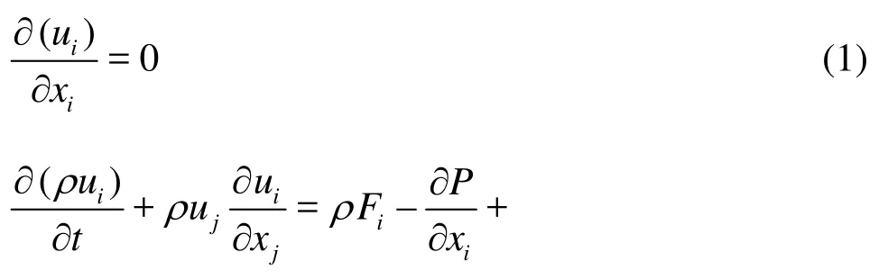
The six degree of freedom motion of the submarine is normally described using two coordinate systems. The first is a right-handed, body-fixed coordinate system, with its origin at a point 2.013 m aft of the forward perpendicular on the hull centerline. The x-axis is positive pointing upstream. The y-axis is positive pointing starboard and the z-axis is positive pointing downward.
The second coordinate systen, an inertial reference frame, is used to define the translational and rotational motions of the body-fixed coordinate system in the earth-fixed coordinates, as shown in Fig.1. In this coordinate syetem, the position of the vehicle’s coordinate system is then expressed in ξ,η,ζ coordinates. The orientation of the body-fixed coordinatesystem is described by Euler angles ψ (yaw), θ (pitch), φ (roll).
Fig.1 Principal earth-fixed and body-fixed coordinate systems
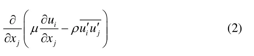
Fig.2 Boundary condition for numerical simulation
1.3 Boundary conditions
The boundary conditions around the submarine model are as follows: The inlet boundary is positioned 1.5 body-length upstreamwith an inflo7w velocity of 4 m/s (Reynolds number of 1.693 × 10 based on the vehicle length), a pressure-outlet condition is defined 3 body-lengths downstream. Free slip wall boundary conditions are applied to the 4 remaining walls 9 diameters away from the model and a no-slip boundary condition is applied to the hull. Figure 2 shows the boundary conditions for numerical simulation.
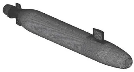
Fig.3 Surface grid of the model
1.4 Mesh def inition
In order to simulate the motion of the model,the fluid domain is split into three regions: aninner region, an outer region, and an intermediate layer between them. The grid is generated by such a hybrid mesh strategy: in the inner region, a multi-block hexahedral mesh is used to define the fluid immediately surrounding the vessel, which allows a detailed control of the mesh parameters and the element quality. The hexahedral mesh is also used in the outer region, which is rather coarse, so the number of grids can be reduced. The intermediate layer consists of unstructured tetrahedral grids, which can be conveniently remeshed in the case of the element deformation, see Figs.3 and 4. The geometry modeling and the grid generation are done by using the Gambit software.
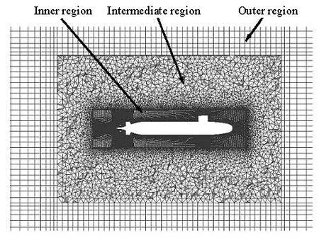
Fig.4 Meshes of three sub-regions
To numerically simulate the oscillatory motion produced in the PMM tests, the User Defined Function (UDF) is used to controlthe motion of the vessel. The outer domain remains fixed in space, while the inner region containing the SUBOFF model moves or rotates to simulate the motion induced in the PMM experiment. It should be noted that the mesh in the inner region remains locked in a position relative to the motion of the vessel. Hence, the mesh of the intermediate layer is deformed to accommodate the motion of the inner region. The new node locations are updated at each time step according to the calculation of the UDF, while the overall mesh topology is maintained. Such a treatment guarantees a high quality of the meshes around the vessel during the maneuvering motion.
2. The grid independence
Before the CFD analysis, the sensitivity of the solution to the resolution of the grid should be determined. Based on an initial grid, a series of successively refined grids were generated. The results from the base grid and the refined grids were compared to check the result variation with the grid refinement.
With the limited computational resource, in the inner region the grid was refined with a ratio ofin t hree directio ns: the lo ngitudi nal , th e transversal andthenormaldirections,whileintheintermediatelayer and the outer region, the refinement ratio was less than. Thecomputational grids contained from 4.33×10⁶cells for the coarse grid to 1.436×10⁷cells for the finest grid.
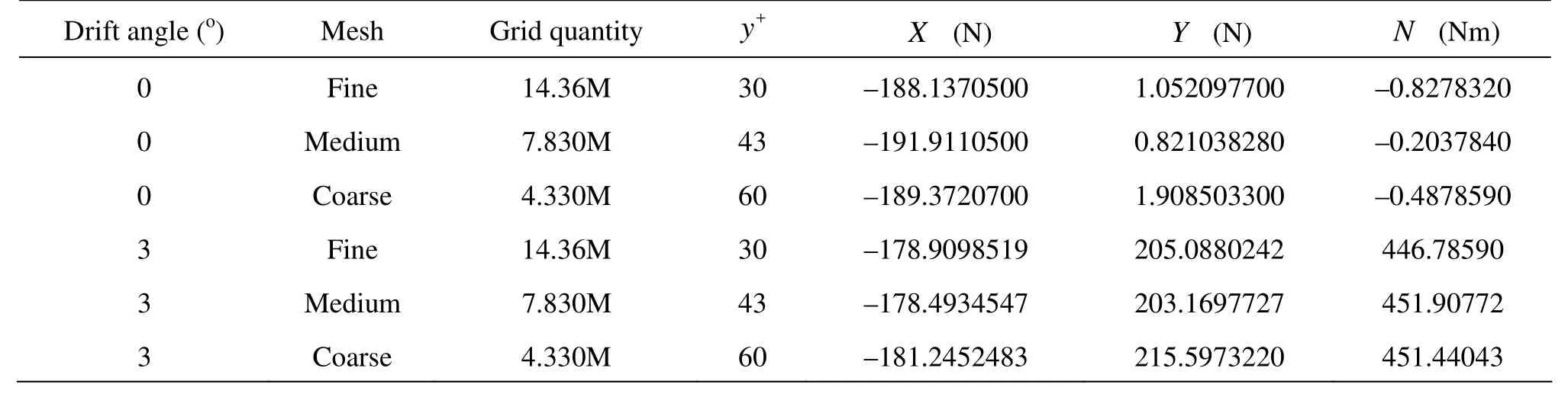
Table 1 Mesh sensitivity
Besides the grid density, the y+value, i.e., the thickness of the first cells adjacent the hull, is also related with the accuracy of the numerical prediction. In this study, the y+value varied from 30 for the finest mesh to 60 for the coarsest. The mesh convergence test was carried out focusing on the forces andothe mo
oments on thevehicle with a drift angle of 0 and 3. Table 1 summarizes the longitudinal forces X, the lateral forces Y and the yaw moments N computed in the tested mesh cases.
From the results in Table 1, it is seen that, on the who le, the solutions do not change significantly from the fine grid to the coarse grid, with only minor differences between results obtained by the fine and medium grids, and a little bit larger differences between the results obtained by the coarse and medium grids. Therefore, the medium grid was chosen for the maneuvering prediction.
Normally, the time step convergence investigation is a necessary step for an unsteady CFD simulation. In Turnock’s paper[13], simulations with 50, 100 and 500 time steps per oscillation cycle were performed. For all three cases, the variations of the sway force and the yaw moment were stabilized after less than a quarter of an oscillation cycle.
Since transient simulations are required to solve the multiple coefficient loops at each time step, further time step refinement would be difficult due to the hardware limitations. Indeed, the study of the temporal discretization convergence would significantly increase the overall cost. With a due review of the published data in literature[13-16], the scheme with 400 time steps per oscillation cycle was adopted for the following transient computations.
3. Numerical simulation of maneuvering motion
3.1 Simulation of oblique towing tests
For the marine hydrodynamics, the CFD techniquehas been developed mainly in the fields of resistance and propulsion. As is known, the oblique towing test is a direct and explicit means of determining the static coefficients and is very similar to the resistance test, except that the model has a fixed attitude during towing. Obviously, it is a logical and natural way to carry out the simulation of the steady oblique towing as an example of the application of the CFD to the field of maneuverability.
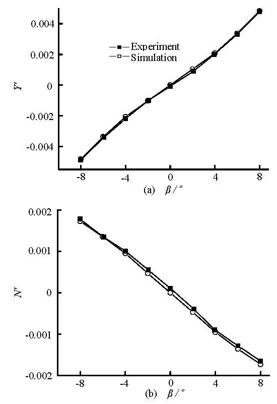
Fig.5 Comparison of the computed and measured lateralforce Y' and yawing moment N'
The model was towed with a straight path ata constant velocity, while for each run the model was setat a prescribed pitch angle or heading angle.Thus theheave velocity v or the sway velocity w ofthe model change according to the following rule

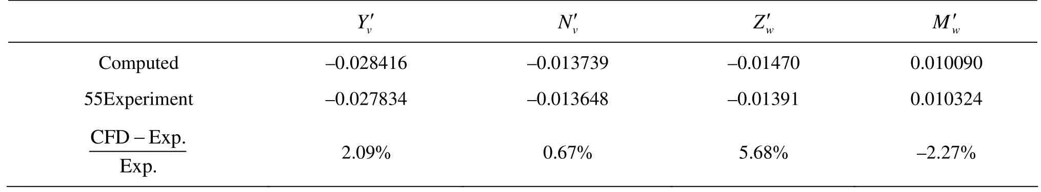
Table 2 Comparison of hydrodynamic force/moment coefficientsdue to transverse velocity
where U∞is the uniform inflow velocity and αis the attack angle,βis the drift angle.
The computed hydrodynamic force and moment are non-dimensionalized as follows
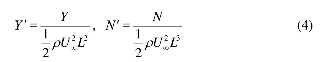
where Lis the length of the model. As shown in Fig.5,thevariation trends of the transverse force and the moment with the drift angles are well predicted. The agreement between the numerical results and the experimental data[12]is good. Similarly, the simulated and the measured normal force Z' and the pitching moment M' are also in good agreement.
3.2 Numerical simulation of planar motion mechanism tests
The PMM generates two kinds of motions: the translation and the rotation, imposed on the vehicle as it travels down the tank at a constant forward velocity. Thesinusoidal motion can be designed in such a manner as to produce the desired conditions of hydrodynamically “pure heaving”, “pure swaying”, “pure yawing” and “pure pitching”. Thus, the rotary-based and acceleration-based coefficients can be explicitly determined.
The system is designed for obtaining the hydrodynamic characteristics of deeply submerged bodies in either the vertical or horizontal planes of motion. For simplicity, the mode of operation applied to the submarine in the vertical plane is discussed here.
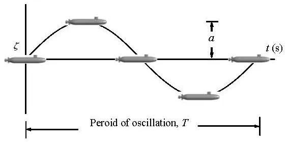
Fig.6 Trajectory of model during pure heaving test
3.2.1 Pure heaving
During the pure heaving motion, the model’s Center of Gravity (CG) moves in such a sinusoidal paththat the pitch angleθ remains zero, as shown in Fig.6. The variation of the vertical displacement, the velocity and the acceleration are given by the following equations.
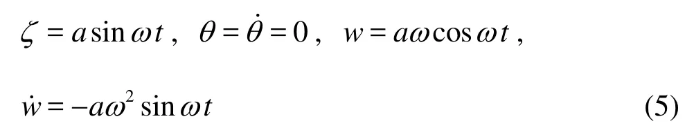
where θ and θ˙ are the angle and the angular velocity in the direction of rotating around the y axis, w and w˙ are the vertical velocity and the acceleration, a is the amplitude, ωis the circular frequencyof the heaving motion.
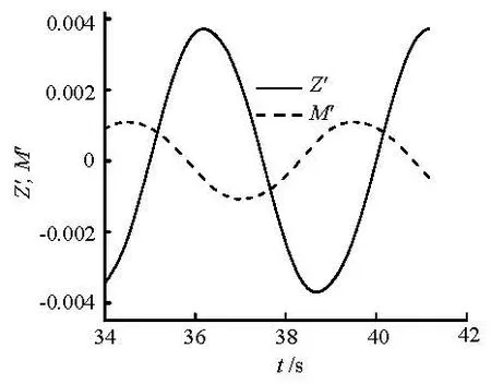
Fig.7 Force and moment acting on the hull during pure heaving test (f=0.2Hz)

Fig.8 The oscillating wake pattern behind SUBOFF in pure heaving motion
The normal force and the pitch moment acting on the hull are monitored as the model oscillates with different frequencies (0.1 Hz, 0.2 Hz and 0.3 Hz). The unsteady RANS simulations are performed for 8 cycles, with the first 7 cycles allowing the system to settle down before the monitoring. Figure 7 shows the time history of the variation of the force and the moment acting on the hull with the oscillating frequency of 0.2 Hz. From these results, the translatory velocity-based and the acceleration-based coefficients Zw'˙,,' can be determined using the Fourier expansion, as shown in Table 3.

Table 3 The hydrodynamic coefficients of the SUBOFF model
As the SUBOFF model oscillates vertically, the flow pattern around the vehicle varies with time.As an example, an instantaneous representation of the velocity field around the vehicle is given on Fig.8.
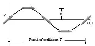
Fig.9 Trajectory of model duringpure pitching test
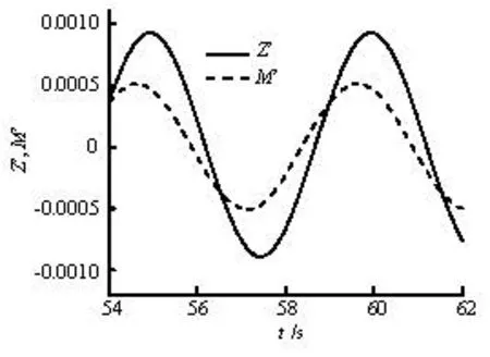
Fig.10 Force and moment acting on the hull during pure pitching test (f=0.2Hz)
3.2.2 Pure pitching
而事实上,丝绸具有在医疗、美容、保健等方面的独特功效和在审美、收藏等方面的文化魅力。在新的科学技术蓬勃发展的背景下,丝绸企业应重视丝绸产品的创新,切实推进桑蚕茧丝绸的综合利用开发。此外,结合当下兴盛的“工业旅游”,丝绸企业借鉴“前店后厂”的模式,完善丝绸体验区的建设,全方位展示丝绸多功能的形象,打破思维僵局,向世界传递丝绸新的消费观念。
The pure pitching motion is one in which the model CG moves in a sinusoidal path while themodel axis remains tangent to the path, that is, the angle of attackα remains zero, as shown in Fig.9. In this case,the pitch angle traces (θ,θ˙,θ˙) are of primary interest.

where θ0is the amplitude, q andare the angular velocity and the acceleration in the direction of rotating around Y axis. The normal force and the pitch moment acting on the hull aremonitored as the model osci llate swit h dif feren t freque ncies (0.1 H z, 0 .2 Hz and0.3Hz).Thetimehistoryvariationoftheforceand the moment acting on the hull with the oscillating frequency of 0.2 Hz is shown in Fig.10. From these results, the rotary rate-based and the accelerationbased coefficients,can be determined using the Fourier expansion, as shown in Table 3.

Fig.11 The oscillating wake pattern calculated behind SUBOFF in pure pitching motion
The flow pattern around the vehicle is shown in Fig.11. In this case, the characteristics of the wake pattern are different from those shown in Fig.8. In studying the velocity field, it can be seen that the rotary motion imposed on the SUBOFF model has a distinct impact on the flow asymmetry and loading.
3.2.3 Results
The motion of the pure swaying is similar to that of the pure heaving, and the motion of the pure yawing is similar to that of the pure pitching. From the results of the above four virtual PMM tests, 16 hydrodynamic coefficients can be determined, as shown in Table 3.
The resulting predictions of the hydrodynamic coefficients show a good correlation with the experimental data. Most of the discrepancies between the predicted hydrodynamic coefficients and the measured values are in the range 0.5%-15% except for a few cases, which are in an acceptable level of accuracy for the preliminary design. The possible source of error lies in the insufficient mesh resolution and the inadequacy of the turbulence model[16].
3.3 Discussions
The overall results indicate that the RANS method can predict the hydrodynamic coefficients in the same level of accuracy as the model test based method. However, the present method might be improved.
In the submarine design, the computational cost may be the main concern that prevents the application of the CFD method. In this study, the unsteady simulations are carried out on a desktop PC using an Intel Core Processor i5 2500 with 16 GB of RAM. A PMM simulation takes approximately 100 h to complete. Thus the total runtime for a set of linear coefficients would be 16 d on a single machine.
Another important issue is that in the preliminary design stages for the submarine maneuverability, a great number of iterations is required, with considerations of various combinations of sizes, locations and configurations of the control surfaces. During such a design process, the changes in geometry in the iteration will make the problem very complex in using the CFD methods and a vast amount of time will be consumed to generate the CFD meshes.
Therefore, a compromise between the semi-empirical method and the RANS method would be more attractive. That is, at the first estimate loop, the semiempirical method is used to determine a small number of design alternatives. And they will be further assessed with the RANS method during the next optimization loop. The accuracy of these predictions is balanced with the calculation speed.
4. Conclusions
A method for the unsteady RANS simulation for the submarine maneuverability is proposed. The method can successfully be used to calculate the flow around a submarine model, and the force and the moment during the steady oblique towing and dynamic PMM motion. The predictions of the static, rotary, acceleration coefficients of the submarine model enjoy an acceptable level of accur acy. The CFD method is shown to be able to provide a good estimate of the maneuveringcoefficients for the fully appended submarine model. However, more studies ae required for more advanced turbulence models, finer grid resolutions and additional verifications and validations before such simulations can be applied with a high degree of confidence.
The main drawbacks of using the CFD method inthe submarine design are that it is time-consuming to obtain the flow solution and to carry out the mesh generation. Advances in the parallel computing and the processor speed can reduce the total simulation time. In view of the iterative design changes, the automatic grid generation should be a desirable technique.
[1] KIM Y. G., KIM S. Y. and KIM H. T. et al. Prediction of the maneuverability of a large container ship with twin propellers and twin rudders[J]. Journal of Marine Science and Technology, 2007, 12(3): 130-138.
[2] LI Gang, DUAN Wen-yang. Experimental study on the hydrodynamic property of a complex submersible[J]. Journal of Ship Mechanics, 2011, 15(1): 58-65(in Chinese).
[3] OBREJA D., NABERGOJ R. and CRUDU L. et al. Identificationof hydrodynamic coefficients for manoeuvring simulation model of a fishing vessel[J]. Ocean Engineering, 2010, 37(8): 678-687.
[4] FAN Shi-bo, LIAN Lian and REN Ping et al. Oblique towing test and maneuver simulation at low speed and large drift angle for deep sea open-framed Remotely operated vehicle[J]. Journal of Hydrodynamics, 2012, 24(2): 280-286.
[5]TYAGI A., SEN D. Calculation of transverse hydrodynamic coefficients using computational fluid dynamic approach[J]. Ocean Engineering, 2006, 33(5-6): 798-809.
[6]WU Ban-shan, XING Fu and KUANG Xiao-feng et al. Investigation of hydrodynamic characteristics of submarine moving close to the sea bottom with CFD methods[J]. Journal of Ship Mechanics, 2005, 9(3): 19-28.
[7]HU Zhi-qiang, LIN Yang and GU Hai-tao. On Numerical computation of viscous hydrodynamics of unmanned underwater vehicle[J]. Robot, 2007, 29(2): 145-150(in Chinese).
[8]BROGLIA R., MASCIO A. D. and AMATI G. A. parallel unsteady RANS code for the numerical simulations of free surface flows[C]. 2nd international Conference on Marine Research and Transportation. Naples, Italy, 2007.
[9] YANG Yong, ZOU Zao-jian and ZHANG Chen-xi. Calculation of hydrodynamic forces on a KVLCC hull in sway motion in deep and shallow water[J]. Chinese Journal of Hydrodynamics, 2011, 26(1): 85-93(in Chinese).
[10] PHILLIPS A. B., TURNOCK S. R. and FURLONG M. Influence of turbulence closure models on the vortical flow field around a submarine body undergoing steady drift[J]. Journal of Marine Science and Technology, 2010, 15(3): 201-217.
[11] GROVES N., HUANG T. T. and CHANG M. S. Geometric characteristics of DARPA SUBOFF models (DTRC Models Nos. 5470 and 5471)[R]. DTRC/SHD 1298-01, 1989, 1-75.
[12]RODDY R. F. Investigation of the stability and control characteristics of several configurations of the DARPA SUBOFF model (DTRC model 5470) from captivemodel experiments[R]. DTRC/SHD 1298-08, 1990, 1- 108.
[13] TURNOCK S. R., PHILLIPS A. B. and FURLONG M. et al. URANS simulations of static drift and dynamic manoeuvres of the KVLCC2 tanker[C]. Proceeding of SIMMAN International Manoeuvring Workshop. Copenhagen, Demark, 2008.
[14] PHILLIPS A. B., TURNOCK S. R. and FURLONG M. The use of computational fluid dynamics to aid costeffective hydrodynamic design of autonomous underwater vehicles[J]. Journal of Engineering for the Maritime Environment, 2010, 1(1): 1-16.
[15] PHILLIPS A. B., FURLONG M. and TURNOCK S. R. Virtual planar motion mechanism tests of the autonomous underwater vehicle autosub[C]. STG-Conference/Lectureday “CFD in Ship Design”. Hamburg, Germany, 2007.
[16] STERN F., AGDRUP K. and KIM S. Y. et al. Experience from SIMMAN 2008-the first workshop on verification and validation of ship maneuvering simulation methods[J]. Journal of Ship Research, 2011, 55(2): 135-147.
10.1016/S1001-6058(11)60311-9
* Project supported by the National Natural Science Foundation of China (Grant No. 11272213).
Biography: PAN Yu-cun (1980- ), Male, Ph. D. Candidate,
Lecturer
ZHANG Huai-xin,
E-mail: hxzhang@sjtu.edu.cn
猜你喜欢
杂志排行

水动力学研究与进展 B辑的其它文章
- DIFFUSING OF AN AMMONIA MOLECULE IN WATER IN A VERY SHORT TIME PERIOD*
- 3-D VARIABLE PARAMETER NUMERICAL MODEL FOR EVALUATION OF THE PLANNED EXPLOITABLE GROUNDWATER RESOURCE IN REGIONAL UNCONSOLIDATED SEDIMENTS*
- NUMERICAL STUDY OF THE PITCHING MOTIONS OF SUPERCAVITATING VEHICLES*
- HEAT TRANSFER OF TiO2/WATER NANOFLUID IN A COILED AGITATED VESSEL WITH PROPELLER*
- A FAST LAGRANGIAN SIMULATION METHOD FOR FLOW ANALYSIS AND RUNNER DESIGN IN PELTON TURBINES*
- TRANSPORT OF BICOMPONENT CONTAMINANT IN FREE-SURFACE WETLAND FLOW*