THE HYDRODYNAMIC CHARACTERISTICS OF FREE VARIABLEPITCH VERTICAL AXIS TIDAL TURBINE*
2012-08-22ZHANGXueweiWANGShuqiWANGFengZHANGLiangSHENGQihu
ZHANG Xue-wei, WANG Shu-qi, WANG Feng, ZHANG Liang, SHENG Qi-hu
Institute of Ocean Renewable Energy System, Harbin Engineering University, Harbin 150001, China, E-mail: zhangxuewei@hrbeu.edu.cn
(Received January 12, 2012, Revised September 6, 2012)
THE HYDRODYNAMIC CHARACTERISTICS OF FREE VARIABLEPITCH VERTICAL AXIS TIDAL TURBINE*
ZHANG Xue-wei, WANG Shu-qi, WANG Feng, ZHANG Liang, SHENG Qi-hu
Institute of Ocean Renewable Energy System, Harbin Engineering University, Harbin 150001, China, E-mail: zhangxuewei@hrbeu.edu.cn
(Received January 12, 2012, Revised September 6, 2012)
The hydrodynamic characteristics of free variable-pitch vertical axis tidal turbine are investigated by combining experimental and numerical simulations. The variations of hydrodynamics are obtained based on testing the kinematics and the dynamics of the turbine under different flow and structural conditions. Through analyzing the movement of the turbine and the characteristics of the flow field by numerical simulations, it is shown how the turbine’s performance is improved.
tidal current energy, vertical axis, variable-pitch turbine, hydrodynamic characteristics, experiments
Introduction
Due to the global climate change and the energy crisis, the clean renewable tidal current energy with high energy density and good predictability has attracted an increasing attention. The vertical axis tidal turbine is one of the core components of the tidal current energy generation system due to its simple structure, the easiness to realize, and the indifference to the flow direction. The hydrodynamics of the turbine would directly influence the energy utilization capability, the manufacture cost, and the service life.
The vertical axis turbine can be classified into the fixed-pitch turbine and the variable-pitch turbine according to the motion style of its blades. The fixedpitch turbine has a simple structure and performs well in low solidity. Extensive researches[1-9]were carried out of its hydrodynamic characteristics under different speed ratios, solidities, pitch angles, and other factors. However, the tidal flow speed is too low generally for a fixed-pitch turbine to self-start, so the flow speed limitation is an issue. Thus the free variable-pitch turbine attracts more and more attention for its excellent self-starting capacity and simple construction. Thefree variable-pitch turbine is characterized by the free swing of its blades within the limit angle and without a special control mechanism. The blades start rotating due to the hydrodynamic and inertia forces. The hydrodynamics of the turbine, however, have not yet been paid enough research attention due to the complex motion of the blades and the interaction of the flow between the blades and the turbine structure, which would generate complex vortex shedding. Hwang et al.[10]and Sun et al.[11]applied commercial software to analyze the hydrodynamics of the cycloid variable-pitch turbine and the spring variable-pitch turbine, respectively, Salvatore et al.[12,13]and Coiro et al.[14]applied the vortex method and the double multiple streamtube method, respectively, to study the hydrodynamics of the free variable-pitch turbine, and the effects of the limit angle and the speed ratio on its performance, but without any discussion on the mechanism.
Above all, in order to optimize the design of the free variable-pitch tidal turbine to achieve a maximum efficiency and to avoid system failure caused by fatigue or overloading, its hydrodynamics should be further studied. This paper makes the investigation by combining experimental and numerical simulation methods. On the one hand, the hydrodynamics and loads related with the free variable-pitch vertical axis tidal turbine are realized by adjusting the turbine structure parameters and the parameters of the flow field experimentally, and the experimental results can alsobe used to verify the numerical simulation. On the other hand, the intrinsic mechanisms to improve the turbine’s performance can be revealed according to the monitored flow details, where the numerical simulation may play an important role. All the results would provide technical support for the design of the turbine.
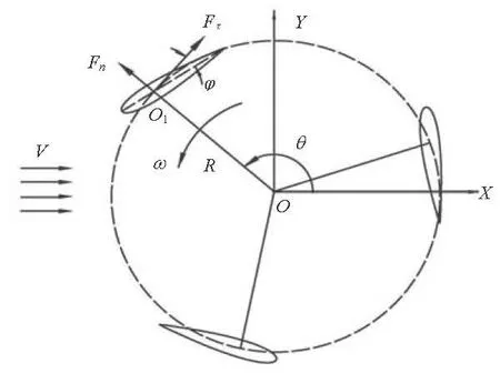
Fig.1 Schematic diagram of free variable-pitch tidal turbine
1. Kinematic and dynamic characteristics of free variable-pitch tidal turbine
The hydrodynamic analysis of a free variablepitch vertical axis turbine involves issues of multibody fluid-solid coupling. On the one hand, every blade is in both rotation and revolution states, which causes a coupled motion between blades. On the other hand, the blade structural motion is coupled with its hydrodynamic behavior. Figure 1 illustrates a schematic diagram of the operation of a straight blade free variable-pitch tidal turbine (consisting of spindle, spoke and blades).
For simplicity, it can be treated as a two-dimensional problem in the analysis, and the following forces or torques act on the unit length of blades. The blades drive the turbine to rotate around the centerO with angular velocityω and radius R under the tangential forceFτand the normal force Fncomes from the flow rate V, andθ is the azimuth of a blade relative to center O. Meanwhile, every blade also rotates around its own axis O1under the hydrodynamic and inertial forces.φ is the pitch angle which is between the chord of the blade and the tangent of the track circle of the turbine. The pitch angle plays a significant role in the hydrodynamic performance of the turbine.
2. Experimental analysis of free variable-pitch tidal turbine
A series of experiments for the free variablepitch vertical axis tidal turbine were carried out on the model test platform for the vertical axis turbine in the water circulating tunnel of Harbin Engineering University in order to study the hydrodynamic characteristics of the turbine systemically, and also to verify the numerical simulation. The work section is 8 m× 1.7 m×1.5 m in dimenssions, with 0.2 m/s to 1.5 m/s in velocity. The main parameters of the turbine are shown in Table 1, and the model is also used in the numerical simulation. The arrangement of the model test platform is shown in Fig.2 and on the platform from right to left are the transmission shaft, the gear, the sensors, the generator and the brake motor. The velocity is measured by the ADCP Nortek AquadoppTM, the torque and the angular velocity are measured by the torque-speed sensor JN338, the azimuth of the turbine is measured by the photoelectric sensor E3F-DS10C4, and the generator output voltage and current are measured by the Hall sensors CHV-50p and CHB–25.
Compared with the fixed-pitch turbine, the free variable-pitch turbine enjoys an obvious advantage with respect to the self-starting performance. Figure 3 shows the variation of the angular velocity in the starting process of the free variable-pitch turbine. When the incoming flow rate increases to the starting speed of the turbine (131 s-135 s), the turbine is in the critical starting condition. The turbine angular velocity is fluctuating with a high frequency when the hydrodynamic torque is close to the variable starting damping torque. With the flow rate increasing and tending to a more stable state (135 s-137 s), the angular velocity increases quickly since the hydrodynamic torque becomes larger than the damping torque. During this period, the angular velocity fluctuates greatly because the torque of blades is varying with the azimuth. When the flow rate reaches the stable value finally (after 138 s), the angular velocity become gradually stable at the runaway speed, which is an average speed because the hydrodynamic torque and the damping torque are in a dynamic balance.
Another advantage of the free variable-pitch tidal turbine is that the hydrodynamic performance in a low speed ratio condition can be improved by changing the range of the limit angle, thus the power performance and the structural performance of the turbine can be improved. Figure 4 shows the experimental results of the energy utilization capability vs. the speed ratio in three different limit angles. It can be seen that the energy utilization capability can be improved significantly by adjusting the limit angle. Figure 5 shows the experimental results of the turbine shaft thrust against the azimuth in the same speed ratio but with different limit angles. It can be seen that the instantaneous value and the average value are different when the limit angles are different, thus the vibration can be attenuated, and the structural performance of the turbine can be improved if the range of limit angles is selected reasonably.

Table 1 Main parameters of the turbine
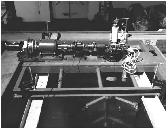
Fig.2 Vertical axis turbine model test platform
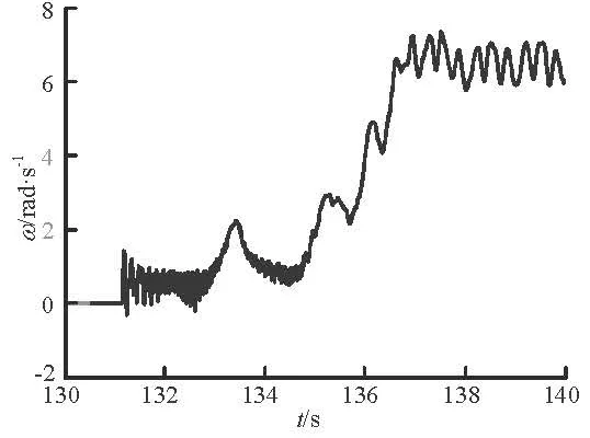
Fig.3 Self-starting process of the free variable-pitch tidal turbine

Fig.4 Energy utilization capability vs. speed ratio
3. Numerical simulation of free variable-pitch tidal turbine
As a supplement to the experiment, numerical simulations were carried out. For such multi-body fluid-solid coupling, the fluid dynamics equations and the structural dynamics equations have to be solved jointly.
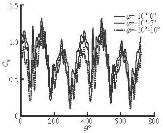
Fig.5 Shaft thrust vs. the azimuth
3.1 Governing equations
3.1.1 Fluid dynamics equation
Because the turbine angular velocity and the flow field velocity are relatively small, the compressibility effect is not considered. For viscous incompressible fluid, the continuity equation and the momentum equation can be used to describe the conservation law of the fluid:
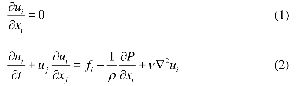
where uiis the speed in i direction,P is the field pressure, fiis the unit mass force, ν is the fluid viscosity coefficient. As the attack angle of blades varies in a large range during the operation process, the SST turbulence model is suitable for such a separation flow, the high precision QUICK format is used for the discretization, and the SIMPLE algorithm is used for the pressure velocity coupling. The steady state is calculated firstly, and then the results are used as the initialization conditions for the unsteady solver.
3.1.2 Structural dynamics equations
For simplicity, the effects of spoke are neglected. Since the elastic deformation is small and the turbine stiffness is large, the elastic force is ignored, and the friction is also ignored for a good bearing lubrication. Equation (3) is the torque balance equation of the turbine relative to point O (see Fig.1). There are two states of the blades in the operation of the free varia-ble-pitch vertical axis tidal turbine. On the one hand, when the blades reach a limit angle, they stop rotating relative to point O1(see Fig.1), so the blade motion equations are not needed. On the other hand, the blades would rotate by inertia and hydrodynamic forces when the blades would not reach the bounds. Based on the D’Alembert principle, Eq.(4) is the torque balance equation of the turbine relative to point.
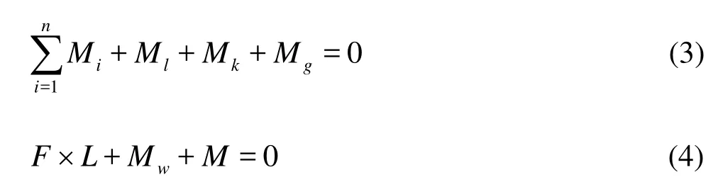
is the total hydrodynamic torque on the turbine (n is the blade number, Miis the torque on blade i relative to point O), Mlis the load torque, Mkis the control torque, Mgis the turbine inertia torque. F and M are the inertia force and the torque on the blades, L is the distance from the blade mass center to the blade shaft. Mwis the hydrodynamic torque relative to point O1. The equation setup process and the parameter solution can be found in Ref.[15].
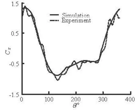
Fig.6 Blade tangential force vs. the azimuth
3.2 Numerical method and validation
In order to simplify the multi-body coupling problem and improve the computational efficiency, this paper adopts the multi-region sliding mesh method[11]and the explicit decoupling formulation. First of all, based on the blade hydrodynamics at time t, Eq.(3) is solved, to get the turbine revolution parameter at time t+Δt , and then based on the turbine hydrodynamics at time t, the blade rotation parameter at t+Δtis obtained by solving Eq.(4). As the elastic deformation is small, the weak coupling method is adopted for the above fluid-structure problem, namely, the fluid dynamic equations are solved first, and then the structure dynamics equation is solved, alternatively in each time step.
Figure 6 shows the comparison of the blade tangential force coefficient Cτagainst the azimuth in the rotation coordinate between the experiment results and the numerical simulation results. Cτ=Fτ/ (0.5ρV2Cb), where C is the chord length, andb is the span length. Good agreement indicates that the numerical method in this paper is valid.
3.3 Results and discussions
In order to reveal how the free variable-pitch vertical axis tidal turbine improves the performance, a series of numerical simulations were carried out.
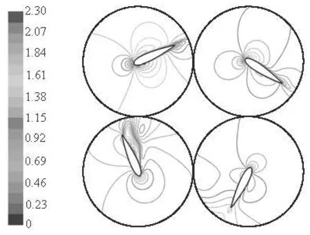
Fig.7 Flow field velocity contours near blade
Figure 7 shows the velocity contours of one blade in the vertical axis tidal turbine in different azimuths. It can be seen that the flow field changes significantly in the blade rotation process, and the attack angle changes with it, especially when the blade is in the third quadrant, the attack angle of blade is larger and the flow separation easily happens. From this observation, the turbine performance will be improved if the attack angle can be adjusted in the rotation process. The attack angle should be enough high and avoid a serious stall.

Fig.8 Blade attack angle vs. the azimuth
Figure 8 shows the attack angle of one blade inthe free variable-pitch vertical axis tidal turbine against the azimuth in the same speed ratio but with different limit angles. It can be seen that with different limit angles, the variations of the rotation and the stay positions of the blade are different, and the attack angle changes. So the tangential force on the blades (Fig.9) and the performance of the turbine can be improved if the limit angle is selected reasonably.
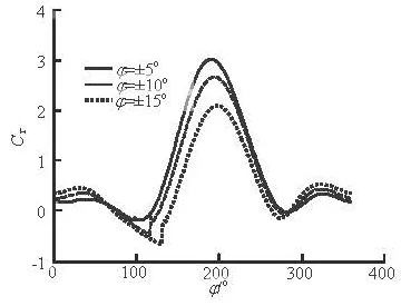
Fig.9 Blade tangential force vs. the azimuth
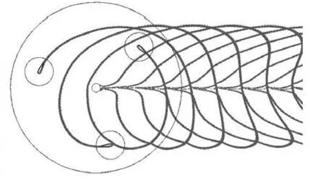
Fig.10 Blade wake of the turbine
The turbine performance is also related to the interference generated by the blade crossing trailing vortex. Figure 10 shows the interference between the blades and the trailing vortex in a certain speed ratio. The interference becomes severe when the blades move to the downstream disk and its effect can be seen in two lights. On the one hand, the interference results in the fluctuation of the hydrodynamic force on the blade which aggravates the fatigue and decreases the structural strength of the blades; on the other hand, the flow rate induced by the trailing vortex is in the opposite direction to the incoming flow rate, thus the power performance of the turbine is reduced. Both the separate position and the spread velocity of the trailing vortex are different for the free variable-pitch tidal turbine with different limit angles.
Figure 11 shows the wake flow field for the free variable-pitch vertical axis tidal turbine induced by the upstream blades against the azimuth in the same speed ratio but different limit angles. It can be seen that the velocity field changes significantly for the downstream blades. So if the limit angle can decrease the interference, the wake flow field effect can be improved, so as to improve the performance of the turbine.
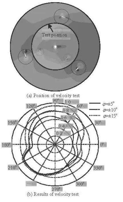
Fig.11 Comparison of velocity magnitude of wake flow field between different limit angles
4. Conclusions
The hydrodynamic characteristics of the free variable-pitch tidal turbine are investigated by combining experiments and numerical simulations, and the following results are obtained.
(1) The free variable-pitch tidal turbine has a good self-starting capacity.
(2) The power performance and the structural performance of the free variable-pitch tidal turbine can be improved by adjusting the range of the limit angle.
(3) The optimization of the attack angle of the rotating blades and the decrease of the interference between the blades and the vortex are the main factors in the improvement of the performance of the free variable-pitch tidal turbine.
[1] CONSUL C. A., WILLDEN R. H. J. and FERRER E. et al. Influence of solidity on the performance of a cross-flow turbine[C]. 8th European Wave and Tidal Energy Conference. Uppsala, Sweden, 2009.
[2] LAIN S., OSORIO C. Simulation and evaluation of a straight-bladed Darrieus-type cross flow marine turbine[J]. Journal of Scientific and Industrial Research, 2010, 69: 906-912.
[3] LI Sheng-mao, LI Yan. Numerical study on the performance effects of solidity on the straight-bladed vertical axes wind turbine[C]. Asia-Pacific Power and Energy Engineering Conference. Chengdu, China, 2010.
[4] KIRKE B. K., LAZAUSKAS L. Limitations of fixed pitch Darrieus hydrokinetic turbines and the challenge of variable pitch[J]. Renevable Energy, 2011, 36(3): 893-897.
[5] PARASCHIVOIU I. Wind turbine design with emphasis on Darrieus concept[M]. Montreal, Canada: Polytechnic International Press, 2002.
[6] KHAN M. J., IQBAL M. T. and QUAICOE J. E. Design considerations of a straight bladed darrieus rotor for river current turbines[C]. IEEE International Symposium on Industrial Electronics. Montreal, Canada, 2006.
[7] CASTELLI M. R., BENINI E. Effect of blade inclination angle on a darrieus wind turbine[J]. Journal of Turbomachinery, 2012, 134(3): 031016.
[8] WANG Ji-feng, PIECHNA J. and MULLER N. A novel design of composite water turbine using CFD[J]. Journal of Hydrodynamics, 2012, 24(1): 11-16.
[9] DAI Y. M., LAM W. Numerical study of straight-blade darrieus-type tidal turbine[J]. Proceedings of the Institution of Civil Engineers Energy, 2009, 162(2): 67-76.
[10] HWANG S., LEE Y. H. and KIM S. J. Optimization of cycloidal water turbine and the performance improvement by individual blade control[J]. Applied Energy, 2009, 86(9): 1532-1540.
[11] SUN Ke, ZHANG Liang and LIAO Kang-ping. Sliding meshes model: Applications to the vertical-axis straightblade hydroturbine[J]. Journal of Harbin Engineering University, 2006, 27(Suppl. 2): 341-345(in Chinese).
[12] SALVATORE F., GRECO L. and CALCAGNO G. et al. A theoretical and computational methodology to study vertical-axis turbine hydrodynamics[C]. Offshore Wind and Other Marine Renewable Energy In Mediterranean and European Seas. Civitavecchia, Italy, 2006.
[13] CALCAGNO G., SALVATORE F. and GRECO L. et al. Experimental and numerical investigation of an innovative technology for marine current exploitation: The kobold turbine[C]. Proceedings of the Sixteenth International Offshore and Polar Engineering Conference. San Francisco, USA, 2006.
[14] COIRO D. P., NICOLOSI F. and De MARCO A. et al. Dynamic behavior of a patented KOBOLD tidal current turbine: Numerical and experimental aspects[J]. Acta Polythecnica International Journal, 2005, 45(4): 77-84.
[15] ZHANG Xue-wei. Numerical simulation on the hydrodynamics of the vertical axis tidal turbine[R]. Postdoctor Report, Harbin: Harbin Engineer University, 2010(in Chinese).
10.1016/S1001-6058(11)60310-7
* Project supported by the National Natural Science Foundation of China (Grant No. 51106034), the Marine Renewable Energy Special Foundation (Grant No. ZJME2010CY01).
Biography: ZHANG Xue-wei (1979-), Male, Ph. D.
杂志排行

水动力学研究与进展 B辑的其它文章
- REVIEW OF SOME RESEARCHES ON NANO- AND SUBMICRON BROWNIAN PARTICLE-LADEN TURBULENT FLOW*
- EFFECT OF A PROPELLER AND GAS DIFFUSION ON BUBBLE NUCLEI DISTRIBUTION IN A LIQUID*
- APPLICATION OF QUADRATIC AND CUBIC TURBULENCE MODELS ON CAVITATING FLOWS AROUND SUBMERGED OBJECTS*
- NUMERICAL PREDICTION OF SUBMARINE HYDRODYNAMIC COEFFICIENTS USING CFD SIMULATION*
- SIMULATION OF OIL-WATER TWO PHASE FLOW AND SEPARATION BEHAVIORS IN COMBINED T JUNCTIONS*
- 3-D NUMERICAL SIMULATIONS OF FLOW LOSS IN HELICAL CHANNEL*