Experimental and CFD Studies on the Performance of Microfiltration Enhanced by a Turbulence Promoter*
2012-02-14LIUYuanfa刘元法HEGaohong贺高红DINGLuhui丁路辉DOUHong窦红JUJia鞠佳andLIBaojun李保军
LIU Yuanfa (刘元法), HE Gaohong (贺高红),**, DING Luhui (丁路辉), DOU Hong (窦红),JU Jia (鞠佳) and LI Baojun (李保军)
1 State Key Laboratory of Fine Chemicals, R&D Center of Membrane Science and Technology, School of Chemical Engineering, Dalian University of Technology, Dalian 116012, China
2 Department of Biological Engineering, University of Technology of Compiegne, Compiegne 60205, France
1 INTRODUCTION
Microfiltration is a pressure-driven membrane filtration process to remove and separate the particles in the range 0.1-10 μm from liquid suspensions. It has been widely used in pharmaceutical, biotechnology,medical, semiconductor, wastewater treatment, wine,dairy, beverage, food and chemical industries [1].However, the separation performance of microfiltration in many applications is seriously hindered by membrane fouling, i.e., the deposition of rejected particles on the membrane surface, leading to blockage of membrane pores or formation of a cake layer, which causes an undesirable decline of permeate flux and high cost of membrane filtration system. Therefore, it is of great importance to alleviate the adverse effects of membrane fouling.
The use of turbulence promoter in the tubular membrane is a simple and effective way to reduce membrane fouling in the crossflow microfiltration(CFMF) of particulate suspensions. Turbulence promoters with different shapes, such as static mixer [2],steel rod [3], twisted wire-rod [4], disc or doughnut shape insert [5], cone shape insert [6] and helical screw insert [7-11], have been developed for various membrane filtration processes. Among these approaches,helical screw insert attracts much attention and interest owing to its excellent streamline shape. For the same reason, we used a helical screw insert to improve the permeate flux of membrane in the CFMF of calcium carbonate (CaCO3) suspension.
Nevertheless, the intrinsic mechanism of flux enhancement by a helical screw insert has not been fully understood, which needs quantitative analysis on the hydrodynamic characteristics inside the membrane modules. Computational fluid dynamics (CFD) is a powerful tool to investigate the processes involved with fluid flow [12-14], heat and mass transfer [15-17],since it can provide plenty of interesting information without recourse to costly experimental work. In recent years, this tool was utilized to describe the complex hydrodynamics generated by rotating disk [18, 19],gas sparging [20, 21] and spacer [22-24] in the membrane modules. For example, Torras et al. [19] carried out a numerical simulation for the fluid flow in a rotating disk filtration module and suggested high permeate flux for the device was due to high shear stresses on the membrane and the absence of stagnant zones inside the module. Cao et al. [22] investigated the effects of various arrangements of turbulence promoters on the fluid flow in a spacer-filled channel and found that the high shear stress and eddies were responsible for the enhanced filtration performance of membrane module.
Unfortunately, the numerical simulation for fluid flow in the helical-screw-inserted tube is limited. It is most likely due to the complexity of the problem and convergence difficulty of numerical simulation. Bellhouse et al. [9] made an attempt and carried out a two-dimensional CFD simulation, but unable to display co-planar velocity vectors and precisely capture the features of flow pattern. Therefore, it is necessary to conduct a three-dimensional (3D) simulation for the fluid flow.
In this study, the filtration performance of membrane is enhanced by a helical screw insert during the CFMF of CaCO3suspension and the effects of operation conditions on the flux improvement efficiency are investigated. To better understand the intrinsic mechanism of flux enhancement, three-dimensional CFD simulation for the fluid flow in the helical-screw-inserted tube is conducted.
2 EXPERIMENTAL
Microfiltration experiments were conducted with a ceramic tubular membrane (Nanjing University of Technology, China) of 15 mm inner diameter and 200 mm length, with average membrane pore size of 0.91 μm.
The helical screw insert, made of stainless steel,is shown in Fig. 1, with the geometrical parameters as follows: the length of helical screw insertL=200 mm,the diameter of helical screw insertDh=13 mm, the diameter of central rodDr=6 mm, the thickness of helix ridgeδ=2 mm, the width of helical grooveλ=12 mm, and the depth of helical grooveh=3.5 mm.
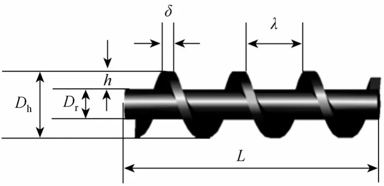
Figure 1 Configuration of a helical screw insert
A laboratory-scale filtration unit consists of a feed reservoir (10 L) thermostated at 30 °C, a peristaltic pump and measuring equipment (pressure gauge,flow meter). In addition, a stirrer was utilized to ensure complete mixing of feed. The test fluid is the suspension of calcium carbonate powder with the median particle size (D50) of 6.18 μm. During a run, both the permeate and the retentate were recycled back to the feed reservoir. The membrane module was rinsed with 0.1 mol·L-1hydrochloric acid solution to restore the pure water flux of the membrane before each experiment.
The pressure drop (ΔP) along the membrane tube was measured with a U-type mercury manometer. The permeate fluxes of membrane with a turbulence promoter (TP) or without it (NTP) were monitored during all of experiments. Flux improvement (FI) efficiency was defined as
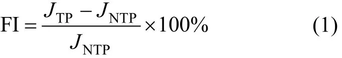
whereJTPandJNTPare the permeate flux of membrane with and without turbulence promoter, respectively.
3 CFD MODELLING
3.1 Model geometry
In order to reduce computational time, the length of helical screw insert is fixed at 50 mm here. Other parameters of helical screw insert are same as those depicted in Section 2. The helical screw insert is centrally inserted in a tube of 70 mm in length, with a distance of 10 mm from the inlet and outlet. Since the tube diameter is 15 mm and the diameter of helical screw insert is 13 mm, the radial clearance gap is 1 mm between the helical screw insert and tube wall.
3.2 Governing equations
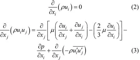
The fluid used for simulation is assumed to be Newtonian and incompressible, and governed by the continuity and Navier-Stokes equations. The timeaveraged continuity and Navier-Stokes equations (Reynolds equations) are as follows [25].
where the second-order tensor of Reynolds stressescan be computed in terms of the Boussinesq hypothesis,
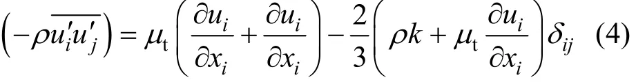
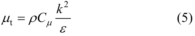
where the turbulent viscosityμtis described as
3.3 Turbulence model
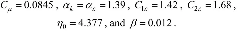
The turbulent viscosityμtcan be calculated with different turbulence models, including the mixing length, standardk-ε, RNGk-ε, Reynolds stress, and algebraic stress models. The RNGk-εmodel is employed here because it is widely applied for the rotating and swirling flows, which are involved in this study.In terms of RNGk-εturbulence model, the turbulence kinetic energyk(m2·s-2) and turbulent dissipation rateε(m2·s-3) are determined by the following equations[25, 26].

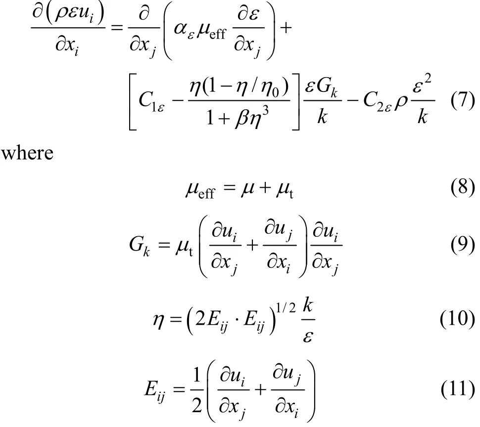
The model constants have following default values:
3.4 Solution method
The software package (FLUENT, v. 6.2.16),which employs the finite-volume method, is used for CFD simulation. In the pre-processing, the geometry modeling of a helical screw insert is created using Pro/Engineer package, and mesh generation is implemented using GAMBIT. Since the permeate rate in industrial membrane processes is often <0.5% of the total crossflow velocity in the channel, the wall suction does not distort the flow field. Therefore, the assumption of non-permeable wall is adopted here,which is widely accepted in literature. In addition, the no-slip boundary conditions are applied to the turbulence promoter and tube wall.
The pressure-velocity coupling is handledviathe SIMPLE algorithm, and the convective terms are discretized by a second-order upwind scheme. A grid size small enough is chosen based on the comparison of results from a succession of finer meshes to ensure that the simulation results are independent of the gird size. Fig. 2 shows the computation grid of local partition of the tube with a helical screw insert.

Figure 2 Computation grid of local partition
4 RESULTS AND DISCUSSION
4.1 Experimental results
4.1.1Effect of turbulence promoter on the permeate flux
Microfiltration of CaCO3suspension was conducted at transmembrane pressure (TMP) of 50 kPa,inlet velocity (uin) of 0.5 m·s-1and feed concentration(C) of 1.0 g·L-1. Fig. 3 shows that the permeate fluxes in both cases decline with filtration time due to the particle deposition on the membrane surface, resulting in additional hydraulic resistance to the filtration flow.Since the surface deposition of particles is accomplished in a few minutes, the cake filtration is expected to govern the filtration process. The initial sharp decline in permeate flux is due to the rapid increase in cake thickness. The permeate flux then declines slowly over a long period and reaches a steady-state value after 70 min, while the cake thickness approaches a certain value. When using a helical screw insert, the steady-state permeate flux is increased by 28%. Flux enhancement is mainly attributed to the reduction in particle deposition on the membrane, since the presence of turbulence promoter in the membrane module yields high wall shear stress, which keeps particles away from the membrane.
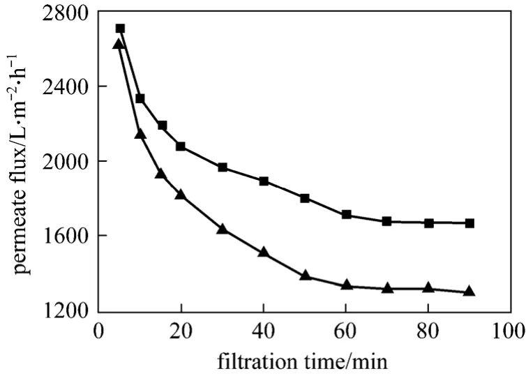
Figure 3 Variation of permeate fluxes with filtration time(C=1.0 g·L-1, TMP=50 kPa, uin=0.5 m·s-1)■ TP; ▲ NTP
4.1.2Effect of TMP on the permeate flux
TMP has an important effect on the permeate flux of membrane, since it is the driving force for a pressuredriven filtration process. Fig. 4 shows that higher TMP yields higher steady-state permeate flux in both cases. However, the permeate flux is not proportional to TMP, since the cake resistance varies with TMP.Higher TMP drives more particles towards the membrane, increasing the particle deposition. Higher TMP also causes depression/consolidation of the cake, increasing the cake resistance. However, the increased cake resistance does not necessarily reduce the permeate flux correspondingly, since higher TMP normally increases the filtrate flux, as predicted by Darcy’s law.
The permeate flux of membrane can be enhanced by turbulence promoter in the tested range of TMP since the increased shearing force drives the depositedparticles away from the membrane. The flux improvement efficiency is more than 25% in the range of 20-50 kPa, but it decays at higher TMP (>50 kPa).Higher TMP increases the drag force of filtration flow,which drives more particles towards the membrane and weakens the effects of turbulence promoter on reducing particle deposition, resulting in the decline of flux improvement efficiency. Therefore, the microfiltration system is better to be operated at lower TMP(<50 kPa) for higher flux improvement efficiency.

Figure 4 Effect of TMP on the steady-state permeate flux(C=1.0 g·L-1, uin=0.5 m·s-1)
4.1.3Effect of inlet velocity on the permeate flux
Figure 5 shows the variation of steady-state permeate flux with inlet velocity. With the increase of inlet velocity, the permeate fluxes in both cases increase, due to the increased wall shear stress associated with a thinner cake layer deposited on the membrane. The curve slope of TP is larger than that of NTP in the range of 0.25-0.5 m·s-1, and the former is smaller than the latter in the range of 0.63-0.75 m·s-1.As a result, the flux improvement efficiency first increases and then deceases with the inlet velocity. The presence of a helical screw insert changes the flow pattern into a swirling flow, which increases the turbulence intensity of bulk flow. At lower flow velocity(<0.5 m·s-1), the swirling flow is sufficient to alter the convection on the membrane surface to a desirabledegree, which enhances the permeate flux effectively.At higher flow velocity (>0.63 m·s-1), the turbulence intensity in the empty tube is so high that the addition of swirling flow does not bring about a major improvement in the permeate flux. Thus the enhanced microfiltration system should be operated at relatively low inlet velocity (<0.5 m·s-1) to obtain high flux improvement efficiency.
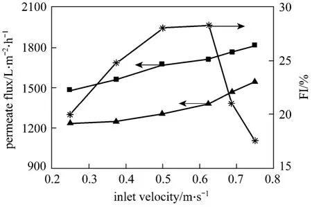
Figure 5 Effect of inlet velocity on the steady-state permeate flux (C=1.0 g·L-1, TMP=50 kPa)
4.1.4Effect of feed concentration on the permeate fluxFigure 6 shows the variations of steady-state permeate flux with feed concentration. The permeate fluxes in both cases decrease with the increase of feed concentration. The permeate flux of NTP declines faster than that of TP in the range of 0.5-10 g·L-1, so that the flux improvement efficiency increases sharply with the feed concentration. For example, it is more than 120% at the feed concentration of 10 g·L-1, indicating that the advantage of helical screw insert is rather predominant at higher feed concentrations.

Figure 6 Effect of feed concentration on the steady-state permeate flux (TMP=50 kPa, uin=0.5 m·s-1)
4.1.5Consideration of energy consumption
The use of a helical screw insert can greatly improve the permeate flux of membrane, but the pressure drop along the tube is higher, increasing the energy cost. Hence the enhanced filtration performance should be checked for the energy consumption. In general, the specific hydraulic energy consumptionEp(kW·h·m-3)is widely adopted [2, 6], which is defined as the energy consumption per unit volume of permeate flow.

where ΔPis the pressure drop along the tube (Pa),Qis the flow rate (m3·s-1),vis the filtration rate of membrane (m·s-1), andSis the effective membrane area (m2).
It can be seen from Fig. 7 thatEpof NTP is higher than that of TP in the tested range of feed concentration except 0.5 g·L-1. With the increase of feed concentration, the energy consumption increase in both cases, but it increases faster in the NTP case. As a result, the ratio ofEpbetween NTP and TP cases sharply increases, indicating that more energy is saved at higher feed concentrations with a helical screw insert.
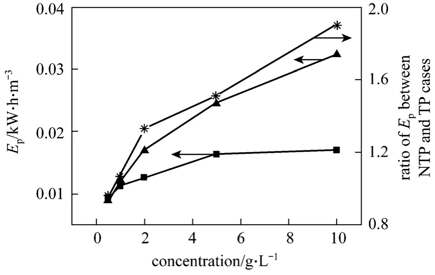
Figure 7 Variation of specific energy consumption with feed concentration (TMP=50 kPa, uin=0.5 m·s-1)
4.2 Numerical results
To explore the intrinsic mechanism of flux improvement by a helical screw insert, 3D CFD simulation of fluid flow was implemented at the inlet velocity of 0.5 m·s-1and the outlet pressure of 50 kPa. The analysis of hydrodynamic characteristics inside the channel is useful for better understanding of the enhanced filtration performance.
4.2.1Velocity vectors
Figure 8 shows the velocity vector in the helicalscrew-inserted tube. The fluid flow in the tube is mainly divided into two parts, helical flow within the helical groove and axial flow through the radial clearance gap [Fig. 8 (a)]. The former is the main part of the total flow with a relatively lower velocity, and the latter is the small one but with relatively higher velocity. The axial flow is helpful to disrupt the boundary layer, and the helical flow can increase the convective mixing. Therefore, the fluid flow is beneficial to improve the filtration performance. Fig. 8 (b) presents the velocity vector in thex-yplane (L=0.023 m), in which the flow pattern of the tube cross-section (in radial direction) is displayed. The fluid is forced to rotate around the central rod of helical screw insert.The rotational flow pattern is the desirable dynamic feature to increases the scouring effect on the membrane surface, reducing the particle deposition.
It is well known that the secondary flow is useful to enhance the permeate flux of membrane, since it introduces the unsteadiness into the bulk flow and increases the mixing of feed. Some researchers [7, 9]suggested that the secondary flow could be generated in the tubular membrane with a helical screw insert.However, our simulation result shows that no secondary flow can be observed within the helical grooves[Fig. 8 (c)]. The similar result was also reported by Guptaet al. [4] through the flow visualization experiment. The absence of secondary flow is mainly attributed to the convective mixing of axial flow and helical flow. The axial flow tends to occupy the helical grove dominated by the helical flow, while the helical flow tends to occupy the radial clearance gap dominated by the axial flow. As a result, the convective mixing of two fluid flows, to a great extent, disrupts the secondary flow. The absence of the secondary flow, owing to the streamline shape of helical screw insert, can reduce the flow resistance.
4.2.2Velocity contours
Figure 9 shows the velocity contours in the tube with a helical screw insert. At the inlet velocity of 0.5 m·s-1, the fluid flow in the whole tube except the entrance region keeps a relatively high velocity [Fig. 9(a)], since the cross-sectional area of the tube is occupied by helical screw insert [Fig. 9 (b)]. The free cross-sectional area for fluid flow is only 75% of the empty tube.
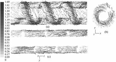
Figure 8 Velocity vectors in the tube with a helical screw insert

Figure 9 Velocity contours in the tube with a helical screw insert
It is important to ensure that dead zones or stagnant regions are absent in the vicinity of tube wall, where the dispersed particles in the feed are readily deposited on the membrane to form a cake layer, increasing the resistance to filtration flow. Although stagnant regions are observed [Fig. 9 (c)], their adverse effect on the flux can be neglected, since they are located in the central part and the exit region of the membrane tube.The absence of stagnant regions in the vicinity of tube wall is the desirable hydrodynamic feature to avoid membrane fouling.
4.2.3Wall shear stress
The filtration performance of membrane module is closely related to the hydrodynamic conditions on the membrane surface. The distribution of wall shear stress (about 0.2 mm away from the top wall) was calculated through CFD simulations, as illustrated in Fig. 10. Compared to the case in empty tube, there is an intense fluctuation of wall shear stresses due to the helical screw insert. The peak values of wall shear stresses appear at the position where the helix ridge is located and the low values occur in the helical groove.The maximum value is obtained at the position ofL=0.01 m, the beginning of helical screw insert,where the flow velocity changes rapidly and intensely.The much higher wall shear stress due to the helical screw insert is the primary reason accounting for the permeate flux improvement, which reduces the thickness of cake layer deposited on the membrane effectively.
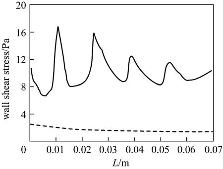
Figure 10 Distribution of wall shear stress TP; NTP
4.2.4Effects of configuration parameters on the wall velocity
The configuration parameters of helical screw insert (Dh,Drandλ) have significant effects on the fluid flow. The increase ofDhvalue decreases the radial clearance gap between the tube wall and the helical screw insert, inducing higher wall velocities, as illustrated in Fig. 11. Similarly, the increase ofDrvalue decreases the depth of helical groove [h=(Dh-Dr)/2],inducing high-speed velocities, as illustrated in Fig. 12.Theλvalue determines the required number of helical turns. As the length of helical screw insert is constant(50 mm),λvalue of 6, 12 and 18 mm approximately corresponds to the number of helical turns of 8, 4 and 3,respectively. The more helical turns are required, the higher wall velocities are generated, as illustrated in Fig. 13.
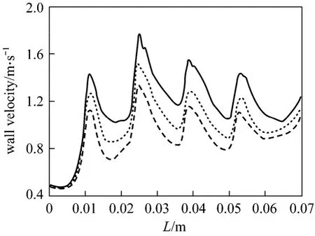
Figure 12 Effects of Dr values on the wall velocity (Dh=13 mm, λ=12 mm)Dr/mm: 8; 6; 4
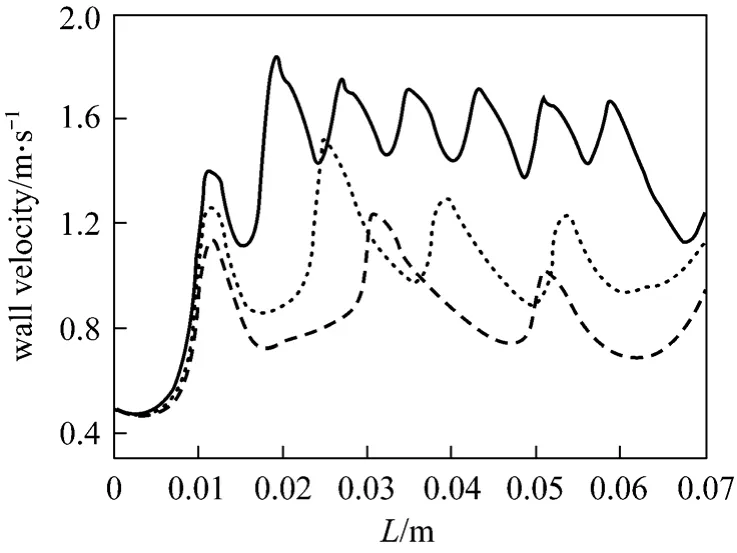
Figure 13 Effects of λ values on the wall velocity (Dh=13 mm, Dr=6 mm)λ/mm: 6; 12; 18
5 CONCLUSIONS
It is efficient to improve the permeate flux of membrane by a helical screw insert in the crossflow microfiltration (CFMF) of CaCO3suspension. The flux improvement efficiency is strongly influenced by the operation conditions. It is suggested that the enhanced microfiltration system should be operated at relatively lower TMP (<50 kPa), lower velocity (<0.5 m·s-1), and higher feed concentration, so as to obtain higher flux improvement efficiency. The energy consumption analysis shows that it is more energy saving at higher feed concentrations.
The hydrodynamics of fluid flow in the membrane tube is entirely changed by a helical screw insert,which is helpful to improve the filtration performance of membrane. The rotational flow pattern increases the scouring effect on the tube wall, reducing the particle deposition on membrane. The absence of secondary flow, owing to the streamline shape of helical screw insert, reduces the flow resistance, lowering the energy consumption. Higher wall shear stress and absence of stagnant regions in the vicinity of tube wall are also responsible for the enhanced filtration performance. The effects of configuration parameters on the velocity fields suggest that the flow velocity increases with the increase ofDhandDrvalues, and with the decrease ofλvalue.
NOMENCLATURE
Cμconstant of the RNGk-εmodel
C1εconstant of the RNGk-εmodel
C2εconstant of the RNGk-εmodel
Dhdiameter of helical screw insert, mm
Drdiameter of central rod, mm
Eijtime-average strain rate, s-1
Epspecific hydraulic energy consumption, kW·h·m-3
Gkgeneration of turbulence kinetic energy, m2·s-2
hdepth of helical groove, mm
Jpermeate flux of membrane, L·m-2·h-1
kturbulence kinetic energy, m2·s-2
Llength of helical screw insert, mm
ΔPpressure drop along the tube, Pa
ppressure, Pa
Qflow rate, m3·s-1
Smembrane surface, m2
TMP transmembrane pressure, Pa
ttime, s
uvelocity, m·s-1
uiicomponent of velocity, m·s-1
ujjcomponent of velocity, m·s-1
vfiltration rate of membrane, m·s-1
xiicoordinate
xjjcoordinate
αkconstant of the RNGk-εmodel
αεconstant of the RNGk-εmodel
βconstant of the RNGk-εmodel
δthickness of helical ridge, mm
δijKronecker sign
εturbulent dissipation rate, m2·s-3
ηstrain rate, s-1
η0constant of the RNGk-εmodel
λwidth of helical groove, mm
μfeed viscosity, Pa·s
μtturbulent viscosity, Pa·s
μeffeffective viscosity, Pa·s
ρdensity, kg·m-3
1 Rahimi, M., Madaeni, S.S., Abolhasani, M., Alsairafi, A.A., “CFD and experimental studies of fouling of a microfiltration membrane”,Chem.Eng.Process., 48, 1405-1413 (2009).
2 Krstic, D.M., Tekic, M.N., Caric, M.D., Milanovic, S.D., “The effect of turbulence promoter on cross-flow microfiltration of skim milk”,J.Membr.Sci., 208, 303-314 (2002).
3 Yeh, H.M., Chen, H.Y., Chen, K.T., “Membrane ultrafiltration in a tubular module with a steel rod inserted concentrically for improved performance”,J.Membr.Sci., 168, 121-133 (2000).
4 Gupta, B.B., Howell, J.A., Wu, D., Field, R.W., “A helical baffle for cross-flow microfiltration”,J.Membr.Sci., 102, 31-42 (1995).
5 Howell, J.A., Field, R.W., Wu, D.X., “Yeast-cell microfiltration—flux enhancement in baffled and pulsatile flow systems”,J.Membr.Sci., 80, 59-71 (1993).
6 Mavrov, V., Nikolov, N.D., Islam, M.A., Nikolova, J.D., “An investigation on the configuration of inserts in tubular ultrafiltration module to control concentration polarization”,J.Membr.Sci., 75, 197-201(1992).
7 Millward, H.R., Bellhouse, B.J., Walker, G., “Screw-thread flow promoter—An experimental study of ultrafiltration and microfiltration performance”,J.Membr.Sci., 106, 269-279(1995).
8 Najarian, S., Bellhouse, B.J., “Enhanced microfiltration of bovine blood using a tubular membrane with a screw-threaded insert and oscillatory flow”,J.Membr.Sci., 112, 249-261 (1996).
9 Bellhouse, B.J., Costigan, G., Abhinava, K., Merry, A., “The performance of helical screw-thread inserts in tubular membranes”,Sep.Purif. Technol., 22, 89-113 (2001).
10 Costigan, G., Bellhouse, B.J., Picard, C., “Flux enhancement in microfiltration by corkscrew vortices formed in helical flow passages”,J. Membr. Sci., 206, 179-188 (2002).
11 Ahmad, A.L., Mariadas, A., “Baffled microfiltration membrane and its fouling control for feed water of desalination”, Desalination, 168,223-230 (2004).
12 Chen, J.B., Liu, C.J., Yuan, X.G., Yu, G.C., “CFD simulation of flow and mass transfer in structured packing distillation columns”, Chin.J. Chem. Eng., 17, 381-388 (2009).
13 Parvareh, A., Rahimi, M., Madaeni, S.S., Alsairafi, A.A., “Experimental and CFD study on the role of fluid flow pattern on membrane permeate flux”, Chin. J. Chem. Eng., 19, 18-25 (2011).
14 Wang, L.H., Cui, J.J., Yao, K.J., “Numerical simulation and analysis of gas flow field in serrated valve column”, Chin. J. Chem. Eng., 16,541-546 (2008).
15 Cai, J., Huai, X.L., Yan, R.S., Cheng, Y.J., “Numerical simulation on enhancement of natural convection heat transfer by acoustic cavitation in a square enclosure”, Appl. Therm. Eng., 29, 1973-1982 (2009).
16 Tesch, K., Collins, M.W., Karayiannis, T.G., Atherton, M.A., Edwards, P., “Heat and mass transfer in air-fed pressurised suits”, Appl.Therm. Eng., 29, 1375-1382 (2009).
17 Licheng, W., Yifei, Z., Xingang, L., Yi, Z., “Experimental investigation and CFD simulation of liquid-solid-solid dispersion in a stirred reactor”, Chem. Eng. Sci., 65, 5559-5572 (2010).
18 Rainer, M., Hoflinger, W., Koch, W., Pongratz, E., Oechsle, D.,“3D-flow simulation and optimization of a cross flow filtration with rotating discs”, Sep. Purif. Technol., 26, 121-131 (2002).
19 Torras, C., Pallares, J., Garcia-Valls, R., Jaffrin, M.Y., “Numerical simulation of the flow in a rotating disk filtration module”, Desalination, 235, 122-138 (2009).
20 Taha, T., Cui, Z.F., “CFD modelling of gas-sparged ultrafiltration in tubular membranes”, J. Membr. Sci., 210, 13-27 (2002).
21 Taha, T., Cheong, W.L., Field, R.W., Cui, Z.F., “Gas-sparged ultrafiltration using horizontal and inclined tubular membranes—A CFD study”, J. Membr. Sci., 279, 487-494 (2006).
22 Cao, Z., Wiley, D.E., Fane, A.G., “CFD simulations of net-type turbulence promoters in a narrow channel”, J. Membr. Sci., 185, 157-176(2001).
23 Koutsou, C.P., Yiantsios, S.G., Karabelas, A.J., “A numerical and experimental study of mass transfer in spacer-filled channels: Effects of spacer geometrical characteristics and Schmidt number”, J.Membr. Sci., 326, 234-251 (2009).
24 Liu, Y.F., He, G.H., Liu, X.D., Xiao, G.K., Li, B.J., “CFD simulations of turbulent flow in baffle-filled membrane tubes”, Sep. Purif.Technol., 67, 14-20 (2009).
25 Fluent Inc., FLUENT User’s Guide, Fluent Inc. (2003).
26 Liu, W., Liu, Z.C., Wang, Y.S., Huang, S.Y., “Flow mechanism and heat transfer enhancement in longitudinal-flow tube bundle of shell-and-tube heat exchanger”, Sci. China Ser. E—Tech. Sci., 52,2952-2959 (2009).
猜你喜欢
杂志排行

Chinese Journal of Chemical Engineering的其它文章
- Phenol Oxidation by Combined Cavitation Water Jet and Hydrogen Peroxide*
- Venting Design for Di-tert-butyl Peroxide Runaway Reaction Based on Accelerating Rate Calorimeter Test
- Effect of Return Sludge Pre-concentration on Biological Phosphorus Removal in a Novel Oxidation Ditch*
- Separation of α-Tocopherol with a Two-Feed Simulated Moving Bed*
- Pervaporation of Aqueous Solution of Acetaldehyde Through ZSM-5 Filled PDMS Composite Membrane*
- Effects of CO2 Dilution on Methane Ignition in Moderate or Intense Low-oxygen Dilution (MILD) Combustion: A Numerical Study*