Fretting Wear Behavior of Medium Carbon Steel Modified by Low Temperature Gas Multi-component Thermo-chemical Treatment
2010-03-01LUOJunZHENGJianfengPENGJinfangHELipingandZHUMinhao
LUO Jun, ZHENG Jianfeng, PENG Jinfang, HE Liping, and ZHU Minhao
Traction Power State Key Laboratory, Southwest Jiaotong University, Chengdu 610031, China
1 Introduction
It is well known that fretting is caused by the relative oscillatory movement of small amplitude which may occur between contacting surfaces subjected to vibration,especially for fasteners subjected to structure oscillating and alternating loading, which may lead to service failure due to rapid crack formation and surface wear[1–4]. In order to alleviate or eliminate fretting damage and to extend the lifetime of components, many researchers have been doing their best to improve the fretting wear resistance of materials by trying various methods[5–6].
Surface engineering, proposed by Prof. BELL, which is regarded as an effective method to improve the wear resistance of materials, has been successfully applied to enhance the ability of components to resist the fretting damage[7–11]. In the past years, the nitriding process with anti-wear, anticorrosion and good fatigue strength, has found a wide industrial application as surface heat treatment technology for varied materials. Many investigations showed that wear resistance of nitrided steels can be attributed to the high hardness and non-metallic character of nitrided layer, with strengthening matrix and reducing adhesion. However, some researches also indicated that brittleness happens to the nitrided layer when excess active nitrogen atoms and/or ions are absorbed in metal surface, with high hardness at the same time, and brittleness is also harmful to wear resistance. To further improve these properties of nitrided layer, penetrating other elements to form a multi-component modified layer has been explored[12–17]. Thus, low temperature gas multi-component thermo-chemical treatment(LTGMTT)technology appeared which simultaneously diffuses various non-metallic elements or metallic elements into the surface of materials at temperatures below the austenitic region[18–19]. The treatment is attracting increasing interest,especially for C-N-S-O penetrating. C could reduce brittleness of ε-Fe2–3N; O could absorb H to decrease hydrogen embrittlement; S could not only enhance activity of C and N to accelerate penetrating rate, but also form solid lubricants in the outer layer of the modified layer. In addition, the compound layer and the diffusion layer also exist in the inner modified layer, which are responsible for the good wear resistance and high fatigue resistance,respectively. Consequently, the LTGMTT is from nitriding but beyond nitriding, and has more excellent comprehensive properties coming from elements penetrated.It is characterized by a lower treatment temperature and shorter treatment time, a high degree of shape and dimensional stability, and process safety and reproducibility.Because of the process characteristics and outstanding mechanical properties, it has been widely applied in the mechanical engineering industry to improve the friction,wear and fatigue properties of constructional parts[20–22].
Medium carbon steel possesses moderate mechanical properties, which has been widely used in the application of modern industry, such as construction industry,communication vehicles and petrochemical industry, etc.However, the low rigidity and wear resistance of the medium carbon steels seriously limited its tribological applications[23–24]. At present, the wear resistance of the LTGMTT modified layer prepared on the surface of medium carbon steel has been studied. But these studies mostly involved in conditions of sliding or rolling with focus on the friction coefficient and wear loss[18–19,25–26]. In fact, many industrial applications of medium carbon steel have operated under fretting condition. The fretting wear and fatigue of nitrided layer have been studied for a long time. Whereas few reports on the fretting of the LTGMTT modified layer can be found up to now[27–29]. Therefore, the purpose of this paper is to understand the fretting behavior of modified layer prepared by LTGMTT on medium carbon steel.
In this study, characterization of the LTGMTT modified layer and fretting wear behavior of LTGMTT modified layer are studied from dynamic behavior, coefficient of friction(COF) and damage mechanisms; finally, the conclusions are drawn.
2 Materials and Experimental Detail
2.1 Preparation and characterizations of modified layer
A contact configuration of flat-on-ball was adopted in tribological tests. The flat specimens, which were machined to the dimensions of 10 mm×10 mm×20 mm with the final surface roughness (Ra) of about 0.07 μm after sanding and polishing, were treated by LTGMTT technology. The substrate of flat specimens was commercial LZ50 (Chinese steel brand) steel, and a 52100 steel ball with diameter of 40 mm and surface roughness of 0.02 μm was used as the sphere specimen.
The chemical composition and main mechanical properties of the two steels are listed in Tables 1 and 2,respectively. Prior to the thermo-chemical treatment, the specimens were ultrasonically cleaned in the acetone and thoroughly dried.
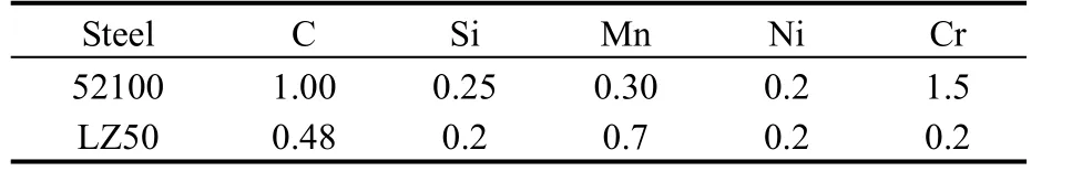
Table 1. Chemical composition and mass fraction of two commercial steels
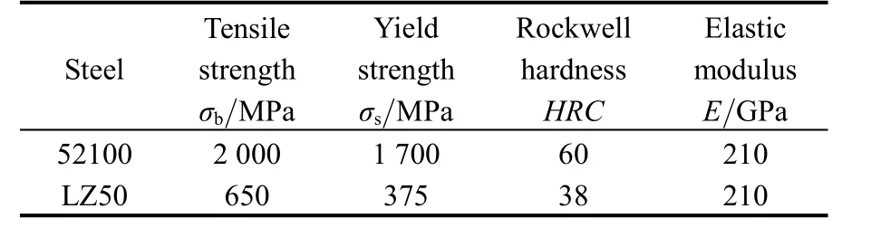
Table 2. Main mechanical properties of two commercial steels
The modified layer was prepared in a low-temperature gas multi-elements penetrating system made by Southwest Jiaotong University, China (Fig. 1). A small hole (diameter of 5 mm) was drilled into each specimen so that it could be hung at the end of an iron wire to facilitate treating in the furnace. During the treatment, the atmosphere was components of NH3, N2and additive. Penetrated elements were chosen as carbon, nitrogen, sulphur and oxygen. Here,the medium carbon steel went through the single stage penetrating process, i.e., rising the temperature to 650 ℃and holding it 2 h. Finally, the specimens were tapped off the furnace and cooled by oil-cooling. After the LTGMTT treatment, the surface roughness of the modified layer was measured by Ambios-technology XP-2 profilometer, and the micro-hardness was measured by Akashi MVK-H21 Vickers hardness tester under a load of 50g. The phase structures of the modified layer were analyzed by PANalytical X-ray diffractometer (XRD). The cross-section morphology of the modified layer was examined by optical microscopy(OM).
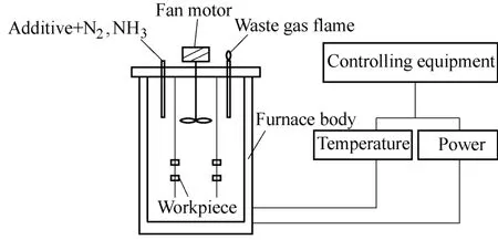
Fig. 1. Low-temperature gas multi-elements penetrating system
2.2 Test methods
A hydraulic tangential reciprocating wear test rig,designed for a ball-on-flat contact configuration (Fig. 2),was used to test the fretting wear behaviors of the modified layer. As seen in Fig. 2, the ball specimen 1 was fixed at the upper holder 2, and was moved with the piston 8 of the hydraulic system. The normal load Fnwas applied by a spring system. The flat specimen 5 was fixed on the lower holder 6, which is mounted on the specimen chamber.Reciprocating movement between two contact pairs (i.e.,the relative displacement of contact system) was measured and controlled by the extensometer 3 and its control circuit.The friction force was measured by the sensor of load cell 4.Counterbalance weigh 7 balanced the weight of ball specimen and upper holder to avoid additional normal load.During the fretting tests, the whole fretting process was computerized and variations of displacement versus normal load can be recorded as a function of cycles.
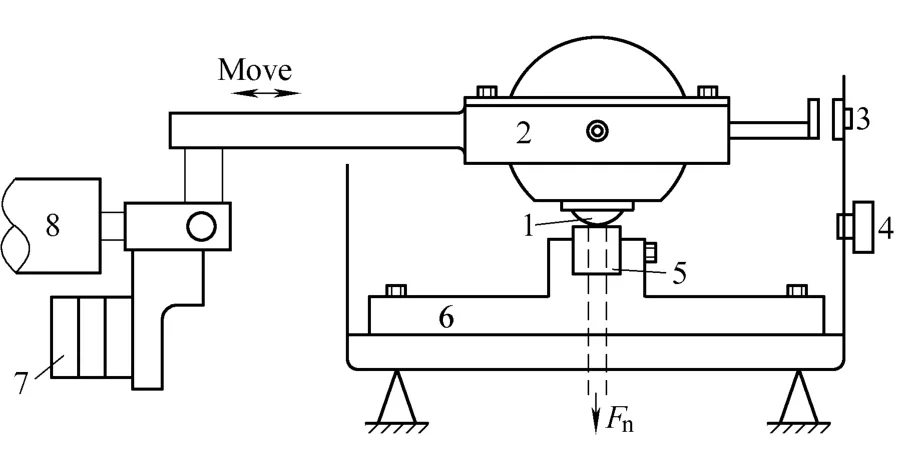
Fig. 2. Fretting wear test rig
Before the fretting wear test, the specimens were ultrasonically cleaned in the acetone and thoroughly dried again. The main test parameters were chosen as follows:the displacement amplitudes varied from 2 μm to 40 μm,the number of cycles was 104, the normal load (Fn) was 150 N, and the frequency was 2 Hz. The fretting wear tests were performed under temperature of 20–25 ℃ and relative humidity of 50±10%. After the fretting wear tests, the morphologies of fretting scars were examined by scanning electron microscopy (SEM, QUANTA2000), and the profile of wear scars was measured by Ambios-technology XP-2 profilometer.
3 Results and Discussions
3.1 Characterizations of the modified layer
The modified layer presented a rough surface with relative roughness of about 2.5 μm. The optical microscopic morphology of cross-section of the modified layer, which was etched by a 4% solution of nitric acid in alcohol, was shown in Fig. 3. Fig. 3 indicated that the modified layer consists of a loose layer, a compound layer and a diffusion layer, with a total thickness of 60 μm.Combined with XRD analysis (Fig. 4) and the distribution of micro-hardness along the distance from the surface to the substrate at its cross-section (Fig. 5), the outer loose layer with pore-rich structure and lower surface hardness,being very thin, was essentially Fe3O4and FeS, and was not visible under OM. The compound layer with the highest hardness (Fig. 5, over twice more than the substrate) and white-bright under OM was mainly composed of γ`-Fe4N and ε-Fe2–3N and small amounts of Fe2C. For the diffusion layer, the hardness reduced gradually to its substrate value,where was located between the white-bright layer and the substrate (Fig. 5).
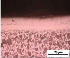
Fig. 3. OM morphology of cross-section of the LTGMTT modified layer
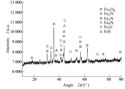
Fig. 4. XRD spectrum of the LTGMTT modified layer
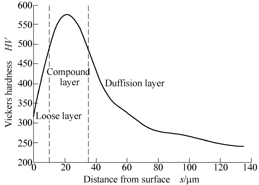
Fig. 5. Micro-hardness distribution curve of the LTGMTT modified layer at its cross-section
3.2 Fretting regimes
For comparison, fretting wear tests of the LZ50 steel substrate against 52100 steel balls were also carried out.According to the variation of Ft(tangential force)–D(displacement amplitude)–N (cycles) curves (i.e., fretting logs), three fretting regimes (i.e., partial slip regime(PSR),mixed fretting regime(MFR) and slip regime(SR)[2,4]) can be analyzed. Under a given normal load of 150 N, the Ft–D–N curves of the modified layer and LZ50 steel at different displacement amplitudes were shown in Fig. 6.
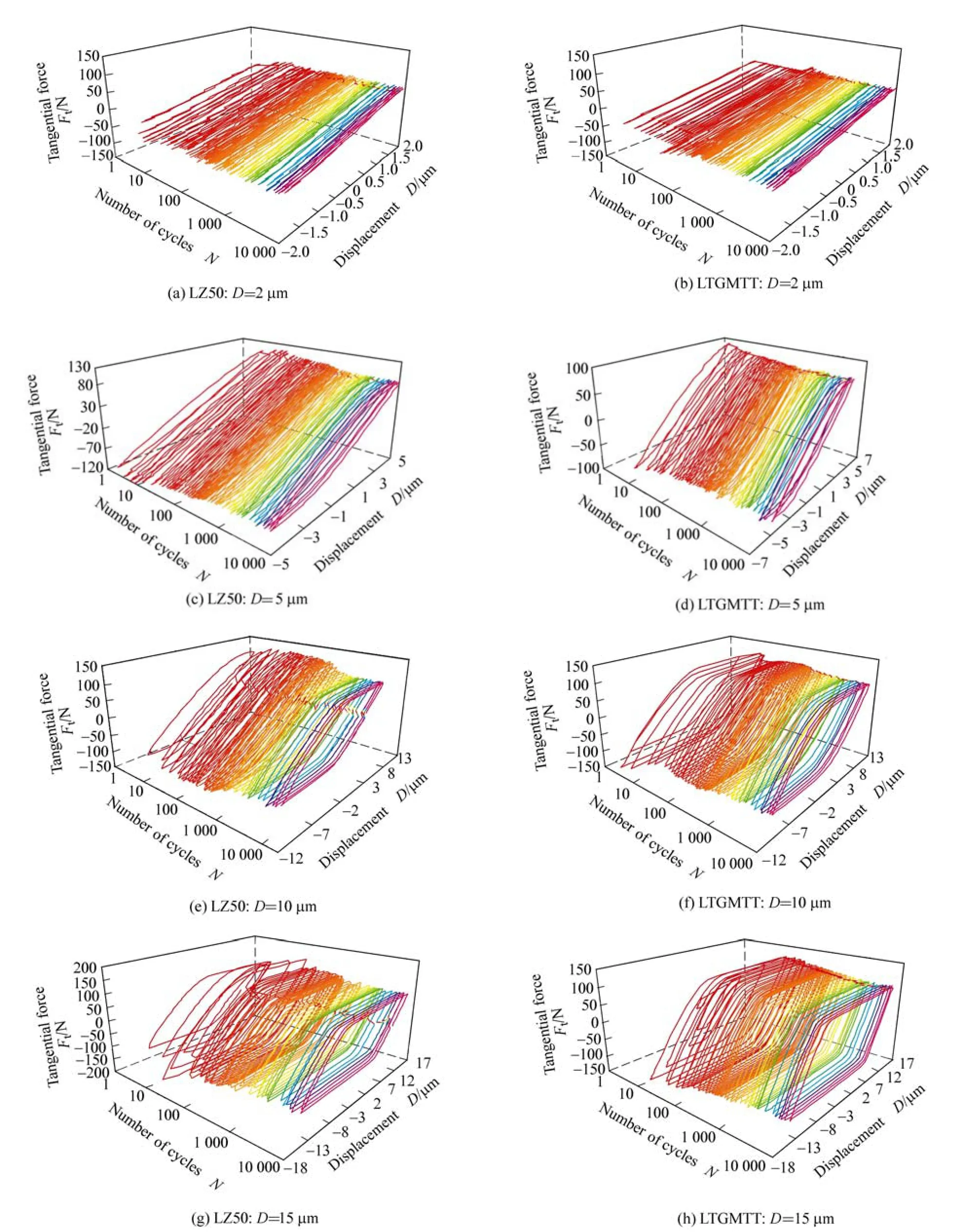
Fig. 6. Fretting logs (Ft–D–N curves) of the LTGMTT modified layer and its substrate under different displacement amplitudes
When D=2 μm (Fig. 6(a)), Ft–D curves were all presented in the shape of line (the tangential force (friction force) increased linearly with the displacement), i.e., only micro-slip occurred at the contact edge while the imposed displacement amplitude was essentially accommodated by elastic coordinate behavior. Therefore, the fretting processes had run in PSR under this condition. However,when D=15 μm (Fig. 6(d)), all Ft–D curves were open in shape of quasi-rectangular, which corresponded to the gross slip occurred at the contact interfaces. The figure indicated the fretting run in SR. For intermediate displacement amplitudes (D=5, 10 μm), all Ft–D curves varied between elliptical and quasi-rectangular loops as function of the number of cycles (Fig. 6(b) and Fig. 6(c)), implying that the fretting had run in MFR[4].
The fretting logs of the modified layer under different displacement amplitudes were shown in Figs. 6(e)–6(h).Only while D=10 μm (Fig. 6(e)), the friction logs had run in PSR. However, when the displacement amplitude increased to 5 μm, the shapes of Ft– D curves were appeared of elliptical loops (see Fig. 6(f)), implying that the fretting had run in condition of mixed fretting regime. For the higher displacement amplitudes (D≥10 μm, Figs. 6(g)and 6(h)), the all fretting loops were appeared in shape of quasi-rectangular, which indicated the fretting regimes were located in SR. As presented in Table 3, it is indicated that the range of the mixed fretting regime of the LTGMTT modified layer became narrow, and the slip regime of modified layer shifted to the direction of lower displacement amplitude. So, the LTGMTT modified layer strongly affected the fretting running regime behavior of the substrate, which maybe attributed to the higher hardness and easy slip capability of the modified layer. On the one hand, the higher hardness of the modified layer caused the contact area to reduce corresponding with the increase of tangential stiffness. On the other hand, the ε-Fe2–3N phase in the compound layer possesses a lamellar hexagonal close-packed microstructure, which is very easy to slip. All of these factors could lead to fretting regime transition to the direction of smaller displacement amplitude.
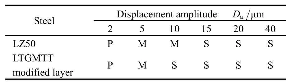
Table 3. Distribution of fretting regimes under different displacement amplitudes
3.3 Coefficient of friction
Fig. 7 displays a general evolution of COF of the modified layer and substrate as function of the number of cycles under different displacement amplitudes at a given normal load (Fn=150 N). It was very obvious that there was a great difference on behaviors of COF between the LTGMTT modified layer and its substrate. The detail analyses of COF in different fretting regimes were presented as follows.
3.3.1 In partial slip regime(PSR)
In partial slip regime with smaller displacement (D=2 μm), COF, more exactly the ratio of tangential force to normal force Ft/Fn, was relatively lower for the modified layer and its substrate during the whole fretting cycles than that in MFR and SR. As shown in Fig. 7(a), only three stages can be observed in PSR, i.e., initial stage corresponding to lower cycles and lower values of COF due to the protection of the “natural pollution” film above sample surfaces, ascendant stage corresponding to the COF quickly climbed from lower level to relatively higher level,and steady stage corresponding to the values of COF stabilized in a small undulant range at higher cycles. The COF of the modified layer was evidently lower than that of its substrate (Fig. 7(a)). In additional, the initial stage for the modified layer was lengthened probably due to its solid lubricant effect in the outer layer. As a result, the steady stage was delayed obviously.
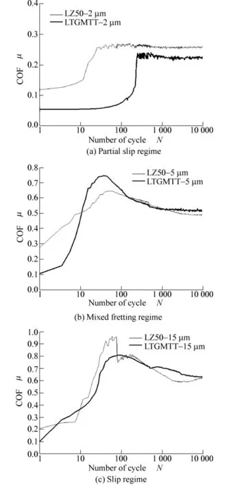
Fig. 7. COF of the LTGMTT modified layer and LZ50 steel in different fretting regimes
3.3.2 In mixed fretting regime(MFR) and slip regime(SR)
From the evolution processes of COF of the modified layer and the substrate as function of the number of cycles in MFR and SR (Figs. 7(b), 7(c)), five stages can be outlined as follows: (1) Initial stage corresponding at lower cycles and lower values of the COF due to protection of surface film. (2) Ascendant stage corresponding to the COF climbed from lower level to higher level because of two bodies immediate contact. (3) Peak-value stage. (4)Descending stage corresponding to the values of the COF declined from peak-value because the third bodies (debris)took part in carrying the imposed load. (5) Steady stage corresponding to the values of the COF stabilized in virtue of the formation and ejection of debris in a dynamic balance state.
Because FeS in the loose layer has characteristics of hexagonal crystal structure, low shear strength, soft in hardness, which means easily slipping along close-packed plane, the COF in initial stage of the modified layer was lower than that of the substrate. However, in the steady stage, a reverse phenomenon was occurred, i.e., the COF of the modified layer was appreciably higher than that of the substrate in MFR and SR (Figs. 7(b), 7(c)). It is indicated that the solid lubricant effect has been disappeared in the steady stage, in other words, the antifriction action for the LTGMTT modified layer only presented in the early stages.
3.4 Damage observations
3.4.1 In PSR
Fig. 8 shows SEM morphologies of the fretting wear scars of modified layer and its substrate in PSR.
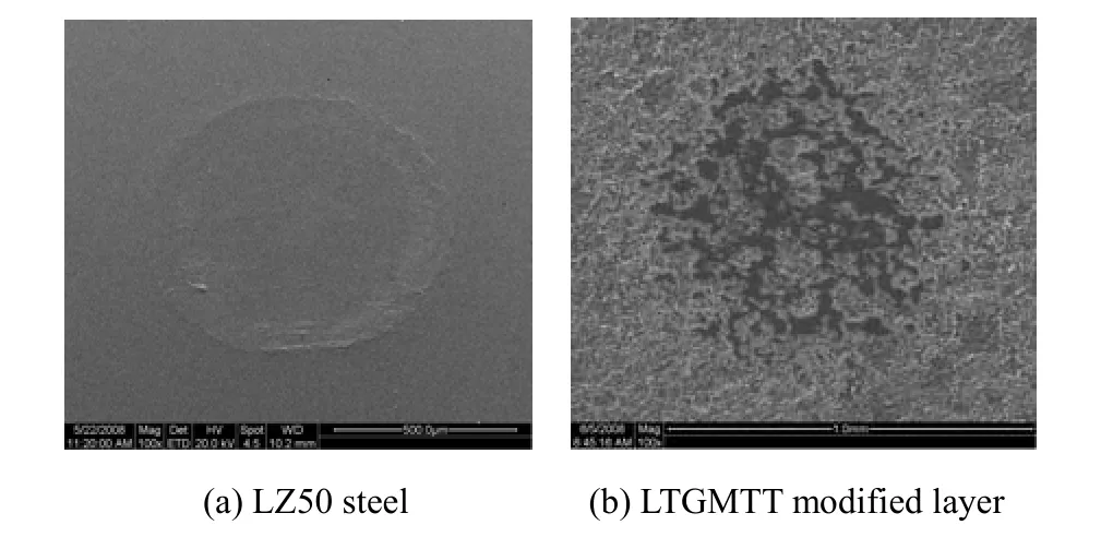
Fig. 8. SEM morphologies of the wear scars of the LTGMTT modified layer and LZ50 steel in PSR
Generally, the PSR corresponds to smaller displacement amplitude which is essentially accommodated by elastic deformation. For the substrate steel, the scar presented a typical morphology of annularity (Fig. 8(a)), where the micro-slip occurred at the contact edge and the sticking occurred at the contact center as in the conventional Mindlin’s condition[2,4]. Some slight ploughing traces were observed in wear annularity. However, for the fretting wear scars of the modified layer, the annular morphology has never been observed in PSR (Fig. 8(b)). Maybe it resulted in for two reasons: Firstly, the rough surface probably accompanied with loose products was squeezed and compacted by the imposed normal load. Secondly, the damage morphology occurred at the central zone was maybe induced by relative sliding in running-in stage at early several cycles. No detachment of the modified layer can be observed, and the porous structure of the modified layer had been still maintained in this fretting regime. It is reason why the COF of the modified layer was lower than that of its substrate all the time during the whole cycles (different from the behaviors in MFR and SR). At the same time, slighter damage for the modified layer was observed than that of its substrate.
3.4.2 In MFR
Compared with the partial slip regime, the degradation was obvious in MFR. As shown in Fig. 9, the traces of the typical plastic flow can be observed at the contact zone of the LZ50 steel, which led to the COF fluctuating at the ascendant stage in MFR and rugged morphology. In addition, a third-body contact was formed due to accumulation of some debris on the contact zones, and detachment of particles mainly occurred in the contact zone.The ploughing traces along fretting direction had been observed at the edge of the fretting scars. Thus, the wear mechanism in MFR for the substrate steel was the combination of abrasive wear and delamination accompanied with plastic deformation.
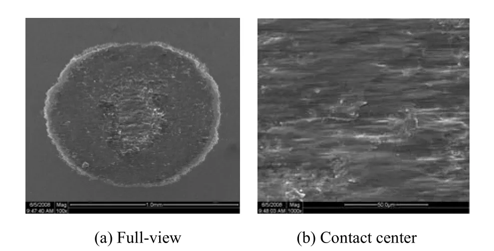
Fig. 9. SEM morphologies of the wear scars of LZ50 steel in MFR (D=5 μm)
For the modified layer, the degradation presented a different morphology from the PSR with the increase of displacement amplitude. As seen in Fig. 10, the pore-rich structure of the modified layer was ground and compacted to a lamellate structure. A few detached particles by delamination and ploughing traces were appeared on the contact zone. Under the same condition, the wear depth of modified layer was shallower than that of the substrate (Fig.11). It is indicated that the modified layer presented better anti-wear property in MFR than that of the substrate.Generally, MFR has been identified to be the most critical regime in crack nucleation, propagation and service failure in fretting[2,4]. In fact, residual compressive stress on the subsurface as a by-product of the LTGMTT technology was helpful to inhibit nucleation and propagation of crack. For the modified layer in MFR, the protection effect was still maintained after 104cycles, which was good for alleviating fretting wear. As a result, the fretting wear mechanism of the modified layer in MFR was main abrasive wear and delamination.
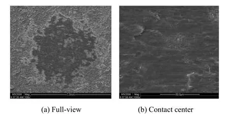
Fig. 10. SEM morphologies of the wear scars of the LTGMTT modified layer in MFR (D=5 μm)
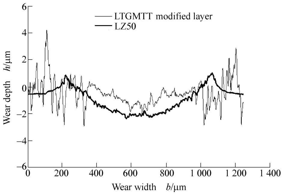
Fig. 11. Profiles of the wear scars of the LTGMTT modified layer and LZ50 steel substrate: D=5 μm
3.4.3 In SR
With the more increase of the displacement amplitudes,the fretting regime entered into the SR and the degradation of LZ50 steel increased consequently. In SR, the width and depth of the wear scars increased with the increase of the displacement amplitudes (Figs. 12, 13). A thicker debris layer covered on the contact zone under the condition of gross slip, and lamellate plate of debris layer can be observed on the fretting scars. In particular, when D = 40 μm, a ring-like zone for debris accumulation was formed between the central zone and the edge zone. The particles detached by delamination and the ploughing by abrasive wear due to the gross slip were the main wear mechanisms in SR.
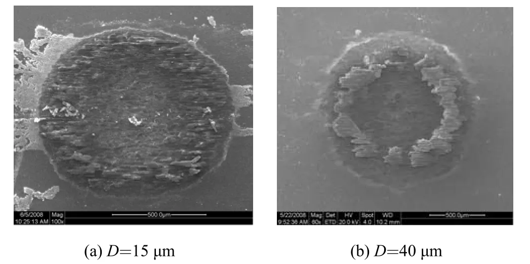
Fig. 12. SEM morphologies of the wear scars of the LZ50 steel in SR
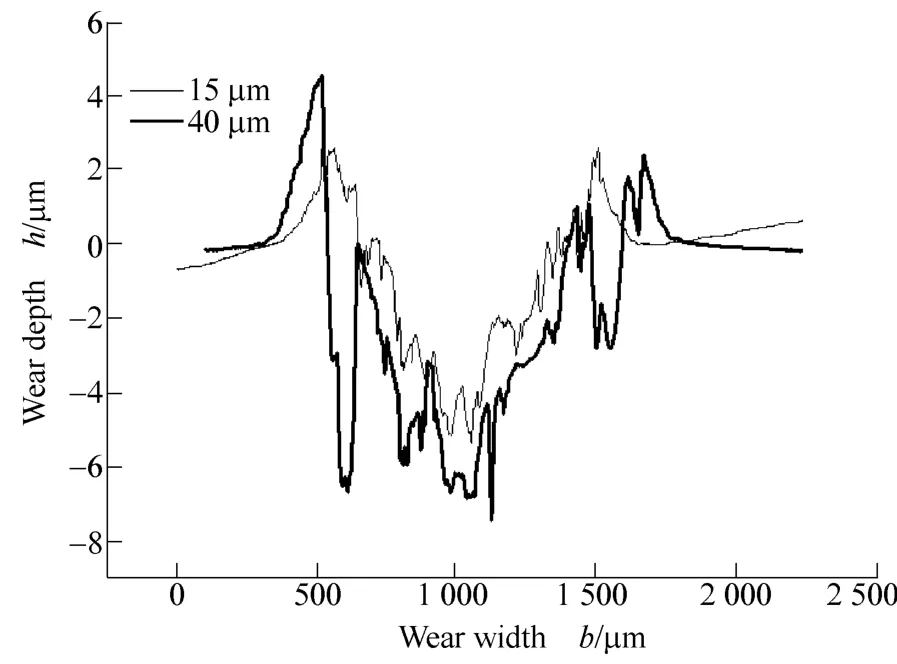
Fig. 13. Profiles of the wear scars of the LZ50 steel substrate in SR
For the modified layer, in SR, similar to the substrate, the degradation increased also with the increase of the displacement amplitudes (Fig. 14).
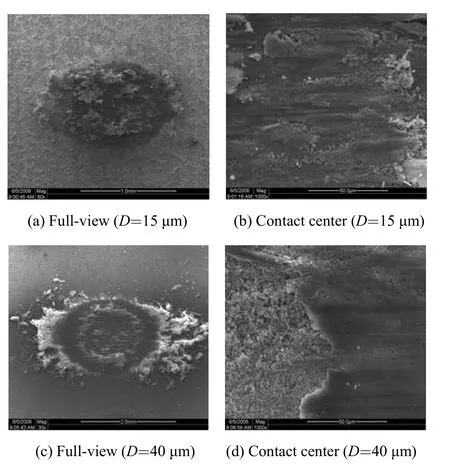
Fig. 14. SEM morphologies of the LTGMTT modified layer in SR
The debris of the modified layer removed incompletely from the contact zone but to form a debris bed. In Figs.14(a) and 14(b), when D=15 μm, a thicker wear debris layer covered on the whole contact zones. The wear depth of the modified layer was lower than that of the LZ50 steel(Fig. 15(a)). The protection effect of the modified layer was still existed under this displacement amplitude after 104cycles. When the displacement amplitude reached 40 μm(Figs. 14(c), 14(d)), the modified layer was worn seriously at the contact centre, and a mass of debris was discharged out the contact zone, which resulted in that the wear depth of modified layer was deeper than that of substrate (Fig.15(b)). It may result that the abrasive wear of the modified layer was accelerated by the hard nitride particles detached from the compound layer. Therefore, the wear resistance of the modified layer was lost under higher displacement amplitudes in SR. Similar to the mixed fretting regime, the wear mechanism of the modified layer was the combination of abrasive wear and delamination.
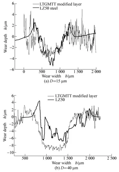
Fig. 15. Profiles of the wear scars of the LTGMTT modified layer and LZ50 steel substrate in SR
As a result, the LTGMTT modified layer presented better wear resistance under condition of fretting wear in PSR and MFR; however, in SR, the wear resistance of the LTGMTT modified layer decreased with the increase of the displacement amplitudes to compare with the substrate,which implied that the LTGMTT surface treatment technique was not suitable in application of under higher displacement amplitude in SR of fretting wear. In PSR,slight abrasive wear was the main wear mechanism for the modified layer. The fretting wear mechanism was combination of abrasive wear and delamination in MFR and SR.
3.5 Mechanisms of alleviating fretting wear
From Table 3, it is clear that the LTGMTT modified layer presented a characterization of changing fretting running regimes, i.e., made MFR narrow and made the slip regime shift to the direction of lower displacement amplitudes. According to the theory of fretting maps[2–4],diminishing the PSR is favorable to alleviating fretting damage, and avoiding the MFR is helpful for reducing the crack initiation and propagation, i.e., reducing the detachment of particles from the LTGMTT modified layer.Therefore, for the LTGMTT modified layer, the changing fretting running regimes was the most important mechanism for anti-fretting damage.
On the other hand, the higher hardness of compound layer and lubricating effect coming from outer loose layer are suitable for reducing the interfacial shear strength,resulting in the decrease of COF. The lower COF is also good for alleviating fretting wear.
To sum up, the mechanisms of alleviating fretting wear for the LTGMTT modified layer can be considered as follows: (1) changing fretting running regimes through diminishing the PSR and left shifting the SR; (2) improving surface hardness by forming compound layer; (3)decreasing COF by solid lubricant of loose layer.
4 Conclusions
(1) The modified layer with thickness of 60 μm consisted of three layers, including an outer loose layer with pore-rich structure, an intermediate compound layer with high hardness, and an inner diffusion layer. The loose layer was main components of oxide (Fe3O4) and sulfide (FeS),and the interlayer was mainly composed by nitrides of Fe4N and Fe2-3N.
(2) The fretting regimes were changed by the LTGMTT modified layer applied, i.e., the boundary of slip regime of the modified layer shifted to the direction of smaller displacement amplitude maybe due to the lubrication effect of the modified layer, resulting in the diminishing of the mixed fretting regime. It is good for alleviating fretting damage.
(3) Different evolutions of COF were appeared in various fretting regimes. In PSR, only three stages can be observed on the curves of COF, i.e., initial stage, ascendant stage and steady stage. The COF of the modified layer as function of the number of cycles in MFR and SR can be outlined five stages, i.e., initial stage, ascendant stage,peak-value stage, descending stage and steady stage. The COF in initial stage of the modified layer were lower than those of the substrate owing to the lubricating effect come from the loose layer. But the friction coefficients in steady stage of the modified layer were appreciably higher than that of the substrate in MFR and SR.
(4) The damage of the modified layer in PSR was very slight, the typical morphology of annularity had not been observed, and the porous structure was still preserved after 104cycles. In MFR and SR, a lamellate structure was formed due to the gross slip. The fretting wear mechanism of the modified layer both in the MFR and SR was identified as the combination of delamination and abrasive wear. The modified layer presented better wear resistance than that of the steel substrate in PSR and MFR; however,in SR, the wear resistance of the modified layer decreased with the increase of the displacement amplitudes due to the formation of hard nitride accelerated the abrasive wear.Therefore, the LTGMTT technique is not suitable to apply under the condition of higher displacement amplitudes in SR.
[1] WATERHOUSE R B. Fretting fatigue[M]. London: Applied Science,1981.
[2] ZHOU Zhongrong, VINCENT L. Cracking induced by fretting of aluminium alloys[J]. J. Tribol. ASME, 1997, 119(36): 36–42.
[3] WATERHOUSE R B. Fretting corrosion[M]. Oxford: Pergamon,1972.
[4] ZHOU Zhongrong, VINCENT L. Mixed fretting regime[J]. Wear,1995, 181/183(2): 531–536.
[5] FU Yongqing, WEI Jun, BATCHELOR A W. Some considerations on mitigation of fretting damage by the application of surface-modification technologies[J]. Journal of Materials Processing Technology, 2000, 99(1/3): 231–245.
[6] CARTON J F, VANNES A B, ZAMBELLI G, et al. An investigation of the fretting behaviour of low friction coatings on steel[J]. Tribol.Int., 1996, 29(6): 445–455.
[7] BATCHELOR A W, STACHOWIAK G W, STACHOWIAK G B, et al. Control of fretting friction and wear of roping wire by laser surface alloying and physical vapour deposition coatings[J]. Wear,1992, 152(1): 127–150.
[8] XU Guizheng, ZHOU Zhongrong, LIU Jiajun. A comparative study on fretting wear-resistant properties of ion-plated TiN and magnetron sputtered MoS2coatings[J]. Wear, 1999, 224(2):211–215.
[9] BLANPAIN B, CELIS J P, ROOS J R, et al. A comparative study of the fretting wear of hard carbon coatings[J]. Thin Solid Films, 1993,223(1): 65–71.
[10] LI C X, SUN Y, BELL T. Shot peening of plasma nitrided steel for fretting fatigue strength enhancement[J]. Materials Science and Technology, 2000, 16(9): 1 067–1 072.
[11] THAIWATTHANA S, LI X Y, DONG H, et al. Comparison studies on properties of nitrogen and carbon S phase on low temperature plasma alloyed AISI 316 stainless steel[J]. Surface Engineering,2002, 18(6): 433–437.
[12] CHO K S, LEE C O. The wear characteristics of ion-nitrided steel[J].Wear, 1980, 64(2): 303–310.
[13] KARAMI M B. An investigation of the properties and wear behaviour of plasma-nitrided hot-working steel (H13)[J]. Wear, 1991,150(1/2): 331–342.
[14] SUN Y, BELL T, WOOD G. Wear behaviour of plasma-nitrided martensitic stainless steel[J]. Wear, 1994, 178(1/2): 131–138.
[15] LEI M K, YUAN L J, ZHANG Z L et al. Tribological studies of plasma source ion nitrided low alloy tool steel[J]. Wear, 1997,209(1/2): 301–307.
[16] ÇELIK A, BAYRAK Ö, ALSARAN A, et al. Effects of plasma nitriding on mechanical and tribological properties of CoCrMo alloy[J]. Surface and Coatings Technology, 2008, 202(11): 2 433–2 438.
[17] TERČELJ M, SMOLEJ A, FAJFAR P, et al. Laboratory assessment of wear on nitrided surfaces of dies for hot extrusion of aluminium[J]. Tribology International, 2007, 40(2): 374–384.
[18] ZHOU Hai, CHEN Fei, YAO Bin, et al. Research on the properties of inside surface of subsurface pump barrel by N-C-O multi-elements penetrating[J]. Surface & Coatings Technology, 2007,201(9/11): 5 165–5 167.
[19] YANG Chuan, GAO Guoqing, WU Daxing. Relationship between microstructure and corrosion resistance of Q235 steel treated by low temperature gas multi-component thermochemical treatment technology[J]. Mater. Prot., 2004, 37(11): 42–43. (in Chinese)
[20] QIANG Yinghuai, GE shirong, XUE Qunji. Sliding wear behavior of nitrocarburized bearing steel[J]. Materials Science and Engineering A, 2000, 278(1/2): 261–266.
[21] QIANG Yinghuai, GE shirong, XUE Qunji. Microstructure and tribological properties of complex nitrocarburized steel[J]. Journal of Materials Processing Technology, 2000, 101(1/3): 180–185.
[22] PODGORNIK B, VIŽINTIN J, WÄNSTRAND O, et al.Tribological properties of plasma nitrided and hard coated AISI 4140 steel[J]. Wear, 2001, 249(3/4): 254–259.
[23] VENKATARRAMAN B, SUNDARARAJAN G. The high speed sliding wear behaviour of boronized medium carbon steel[J].Surface & Coatings Technology, 1995, 73(3): 177–184.
[24] THAWARI G, SUNDARARARJAN G, JOSHI S V. Laser surface alloying of medium carbon steel with SiC[J]. Thin Solid Films, 2003,423(1): 41–53.
[25] ZHOU Hai, LV Junxia, CHEN Fei, et al. Study on corrosion resistance of blowout preventer material by multi-component infiltration[J]. New Technology & New Process, 2006(7): 59–60. (in Chinese)
[26] JIE Xiaohua, DONG Xiaohong. HUA Nacan, et al. Study on the performance of the penetrated layer of HI3 steel by C-N-O-S-B five-elements penetration[J]. Heat Treatment of Metal, 2002, 27(7):21–23. (in Chinese)
[27] DENG Yunshu, ZHANG Baoyu, LUO Weili. The fretting behaviour of a nitrided steel 38CrMoAl[J]. Wear, 1988, 125(1/2): 193–204.
[28] ALLEN C, LI C X, BELL T, et al. The effect of fretting on the fatigue behaviour of plasma nitrided stainless steels[J]. Wear, 2003,254(11): 1 106–1 112.
[29] RAJASEKARAN B, GANESH S, RAMAN S. Plain fatigue and fretting fatigue behaviour of plasma nitrided Ti-6Al-4V[J].Materials Letters, 2008, 62(16): 2 473–2 475.
杂志排行

Chinese Journal of Mechanical Engineering的其它文章
- Precision Grinding of Reaction Bonded Silicon Carbide Using Coarse Grain Size Diamond Wheels
- Chemical Mechanical Polishing of Glass Substrate with α-Alumina-g-Polystyrene Sulfonic Acid Composite Abrasive
- Auditory-model-based Feature Extraction Method for Mechanical Faults Diagnosis
- Discrete Stress-strength Interference Model of Reliability Analysis under Multi-operating Conditions