Modeling and Simulation of Cavitating Flow over Underwater Vehicle with Large Angle of Attack
2010-02-27CHENYingLUChuanjingGUOJianhong
CHEN Ying,LU Chuan-jing,GUO Jian-hong
(School of Naval Architecture,Ocean and Civil Engineering,Shanghai Jiao Tong University,Shanghai 200240,China)
1 Introduction
High-speed underwater vehicles deviating body direction from moving direction may often get damaged by the asymmetrical cavity appearing around the body.To reveal the mechanism of such damage and research the rule of cavity characteristics at large attack condition,numerical simulation was carried out.
Along with the development of computer,numerical simulation methods of cavitation flow have been improved greatly.Some cavitation models based on solving N-S equations have been adopted,most of which belong to Homogenous-Equilibrium-Model(HEM).Merkle et al[1]put forward a HEM model based on barotropy relation ρ=ρ(p).This approach was also used by Byeong et al[2]to predict period phenomenon of internal flows through duct and nozzle,and used by Wu and Lu[3-5]to simulate laminar cavitating flows around 2-D hydrofoil and 3-D axis-symmetric body,and used by Chen et al[6]to simulate periodic cavity shedding in Venturi tube or around NACA hydrofoil.Since this model considers evaporation or condensing as an abrupt phase change process,but not a gradual process,it has convergence problem for complicated flows.Kubota et al[7]proposed a second kind of model which established a relation between local void fraction and mixture density,based on Rayleigh-Plesset equation.This so called Bubble Two-phase Model(BTM)adapts to compute cloud cavitation rather than sheet cavitation and super cavitation.Markatos[8]used a third kind of model to solve equation sets of liquid phase and gas phase respectively.However,it costs computer resource almost twice.
The currently most extensively used models are HEMs based on solving liquid-phase fraction equation.Kunz[9]proposed such kind of model to simulate partial sheet cavities.Fu et al[10]used such model to compute cavitating flows around revolution body.Chen et al[11]used it to simulate partial cavity and super cavity over underwater vehicle of complex structure.Singhal et al[12]proposed another HEM model based on vapor-phase fraction equation deduced from Rayleigh-Plesset bubble dynamics equation.Chen et al[13]used this model to validate computation program by simulating simple revolution body.Hu et al[14]adopted it to study the interaction between ventilated cavitating flow and exhausted gas of an underwater vehicle.Chen et al[15]used it to research the wall effect on cavitating flow over this underwater vehicle in water tunnel.
To simulate full 3-D cavitation problems of complex conditions credibly,the authors developed a reliable and robust computer program.The adopted physical and mathematical models will be narrated in the following part of this paper.
2 Mathematical model and numerical method
2.1 Mathematical model
The basic approach consists of solving the standard 3-D RANS equations,energy equation,turbulence model equations,and vapor fraction equation of cavitation model.A multiblock structured mesh based SIMPLE type sequential solver was set up.
The RANS equations are listed below:


in which,μ and μtindicate molecular viscosity and turbulence viscosity respectively.σkand σεindicate Prandtl numbers.Ck,Cε1and Cε2are model constants with modification for low Re.The extra non-linear Reynolds stress in RANS equation is as follows:

in which,Sijand Ωijare velocity strain tensor and rotation tensor respectively.
Singhal et al’s cavitation model based on equation of vapor mass fraction fvis as follows:

in which,k indicates turbulent kinetic energy;σ indicates surface tension of fluid;Ceand Ccare empirical parameters.The source terms are deduced from Rayleigh-Plesset bubble dynamics equation,which is shown in Eq.(7),with some reasonable hypothesis.This cavitation model reveals the nature of cavitation generation and collapse more essentially,which guarantees its convergence and stability when used to small cavitation number conditions.

The mixture density is a function of liquid or vapor mass fraction(flor fv),which are computed by solving fvequation coupled with RANS equations.The ρ-f relationship is:

and in the upper equation,the relationship of fl+fv=1 exists.
2.2 Numerical method
The solver bases on multi-block non-orthogonal structured grid,which adapts to complex geometry.Finite Volume Method(FVM)was used to discretize the computation domain.Colocated variable arrangement of grid was adopted.Full Multigrid Method(FMG)using V-cycles was also included to accelerate convergence.
A segregated solver was used,and implicit method was adopted to discretize the equations,that means,the volume center variable,φP,and its neighbors,φnb,are assumed to be unknown in each outer iteration cycle.Under-relaxation factors were used in the outer iteration when sequentially computing the coupled non-linear equations.
Since mixture approaches were adopted for the cavitation models to consider the fluid field as a continuous density variation area,a SIMPLE type implicit scheme of Pressure-Velocity-Density coupling was used to solve the pressure-correction equation to insure the continuity.
For solving the unsteady terms in any Reynolds’transport theorem type equations in our code,the Three-Time-Level Method was adopted,namely,after subtracting the unsteady term in continuity equation,the)dV can be approximated as follows:

For surface integrals,namely,),midpoint rule was adopted.That is,the integral was approximated as a product of the integrand at the cell face center and the cell face area.
For convective terms,first order upwind scheme with deferred correction was used in outer iteration cycle to compromise convergence,stability,and accuracy.That means,the convective fluxcombines the low-order implicit part and the correction part explicitly calculated with variable values in the old iteration step.TVD scheme was also included in our code to capture great gradient if necessary.
For diffusive fluxes,deferred correction was also used,which is described asThe implicit part adopts weighted central scheme.
The Strongly Implicit Procedure(SIP)method was used to solve the discretized algebra equations iteratively.For multi-block grid,in each inner iteration cycle,the equation set was solved block by block.For control volumes besides block interfaces,the values of neighboring blocks were used explicitly.
In the phase fraction equations of cavitation model,f equation can composes simultaneous equations with the continuous equation,thus,the coefficient matrix of discretized algebraic equations has the advantage of diagonal dominance and good iterative convergence.When the f equation is discretized,usingto denote the mass flux through the ‘east’surface,the convective term should beand the sum at all surfaces of the control volume is as follows:


The plus convective flux termscan be eliminated by subtracting Eq.(10)from Eq.(9),and this makes the diagonal coefficients of f in the algebraic equation dominant.
After discretizing Eq.(2)implicitly,two computation steps were executed in every time step Δt.The first step is to solve the implicitly discretized momentum equations by iteration.Eq.(11)denotes the number-m outer iteration,in which,the number-m intermediate velocity fieldis calculated using pm-1andobtained in the last iteration.


where,ΔΩ is the volume of control volume,k is the number of faces of the control volume.Putting the discretized continuous equation=0 and correction relationsomitting the high-order quantities,rearranged as:

Utilize the upper equation and compressive relation ρ′=Cρp′,the pressure correction p′can be computed.
1.1.2 预测试对象 采用目的抽样,拟选取2017年11月~2018年1月某综合性医院127名护士进行预测试。纳入标准:目前在职工作并取得资格证书的护士;工作时间至少满1年;知情同意。排除标准:1年内在2家及以上医院工作的护士;不愿意参加本次调研。预测试对象127名,男1名(0.8%)、女126名(99.2%);年龄22~49(31.14±5.24)岁;初始学历:大专78名(61.4%),本科47名(37.0)%,研究生2名(1.6%);工作年限1~20(7.71±6.47)年。
3 Computational results and discussion
The research works were carried out about the large attack cavitating flows around a kind of underwater vehicle,the model of this vehicle and the computational grid are presented in Fig.1.
In all the computations below,the working fluid was liquid at 293K,liquid and vapor densities are 1 000kg/m3and 0.554 2kg/m3respectively,saturation pressure is 2 350Pa,surface tension is σ=0.071 7N/m.Accordingly,incoming velocity of U∞=10m/s(Re≈105)was used.Working condition of σ=0.01~0.6 and α=0°~20°were studied in detail,where the cavitation number σ is defined as σ =
Fig.2 presents the computed 3-D fviso-surfaces(fv=0.1)over this vehicle at different large attacks,each attack was shown in three views.Fig.3 presents the experimental photos by Quan et al[16],each attack shows two views.

Fig.1 Vehicle model and 3-D computational grid

Fig.2 Iso-surfaces of fv=0.1(σ=0.3)
By comparison,computational results and experimental images are similar at the following aspects:
(1)At identical attack,cavity length distribution follows:side direction>suction side>pressure side.(2)Cavity lengthes of suction side change little for different attacks.(3)When attack increases,cavity of side direction prolongs,while cavity length of pressure side decreases obviously.
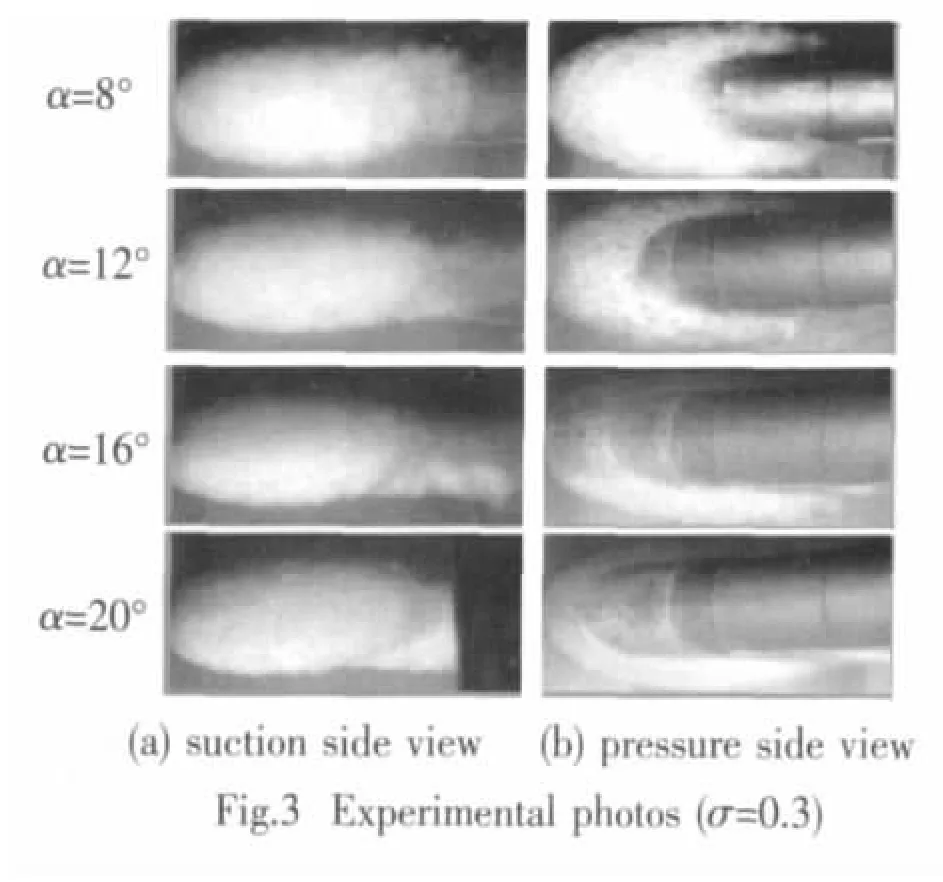
These indicate that the computation results have good agreement with experiment in cavity shape.
In the following part,the characteristic dimensions of the large-attack cavities were studied in detail to conclude some quantitative relations between cavity dimensions and cavitation number and attack.
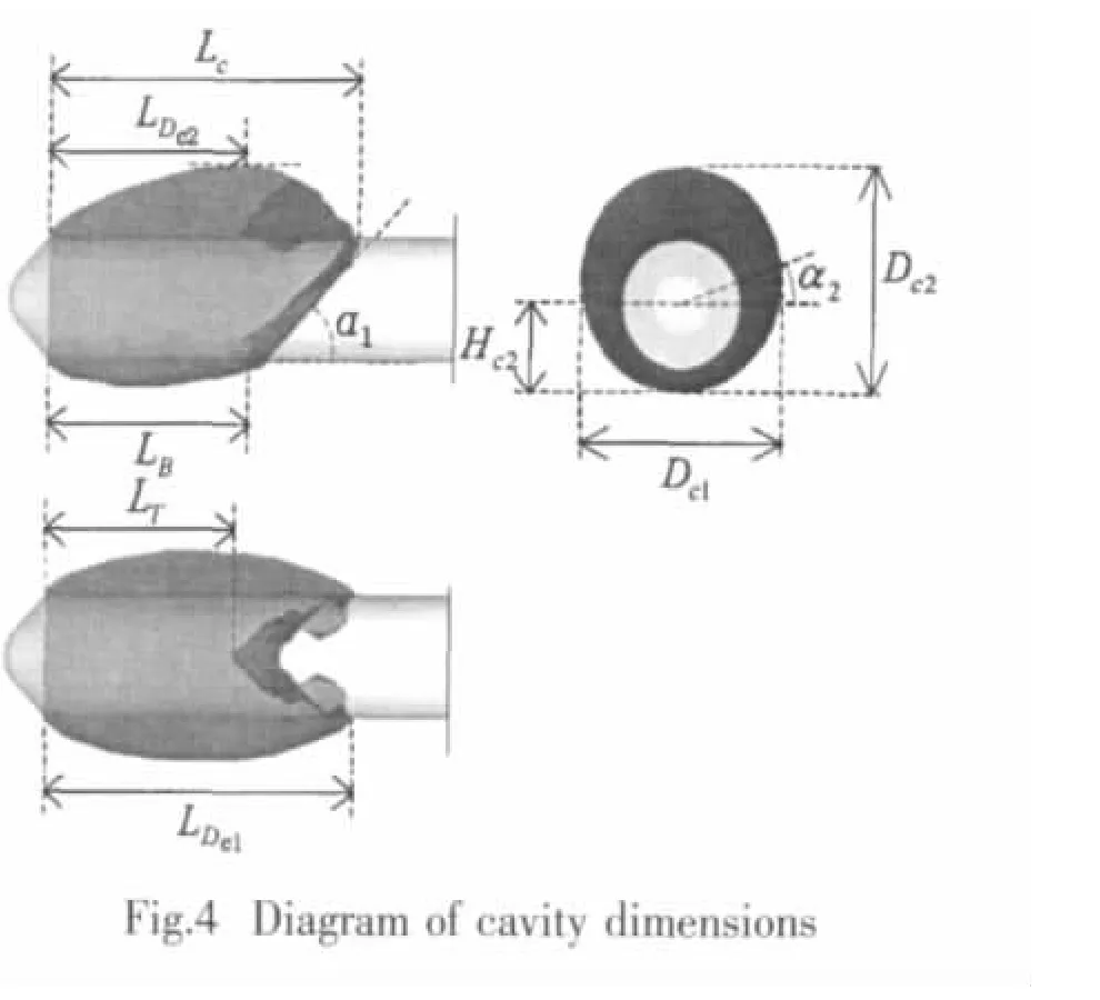
Fig.4 presents the diagram of some main dimensions of cavity shape.This diagram is for the working condition of σ=0.3 and α=8°.
Fig.5 shows the four types of cavity length dimensions indicated in Fig.4.The following regulations can be found:(1)The cavity main length LDc1has little relation with the attack of vehicle,but just increases along with the decreasing of cavitation number σ.(2)The cavity length on suction-side wall,viz.LT,increases slowly along with the increasing of attack,and the variation ratio changes little at different cavitation numbers,except σ=0.2,when cavitation also occurs from the side of vehicle body.(3)The cavity length on pressure-side wall,viz.LB,decreases along with the increasing of attack,and the variation ratio increases relatively remarkablely when cavitation number reduces.
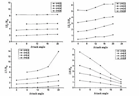
Fig.5 Main length dimensions of cavity
Fig.6 shows the two types of cavity diameter dimensions indicated in Fig.4.The following regulations can be obtained:(1)The cavity diameter at abscissa direction,viz.Dc1,has little relation with the attack of the vehicle.(2)The cavity diameter at ordinate direction,viz.Dc2,increases slowly along with the increasing of attack.
Fig.7 shows the two types of cavity angle dimensions indicated in Fig.4.The approximate regulations can be found:(1)The angle of intersection by cavity surface and vehicle wall,viz.α1,reduces along with the increasing of the attack of vehicle.Additionally,the variation ratio increases when the attack reduces.(2)The angle of the maximal diameter of abscissa direction,viz.α2,increases along with attack,however,the difference of α2 for different cavitation numbers becomes greater when the attack becomes larger.At the relatively small attack of α=4°,the difference even turns into nearly zero.
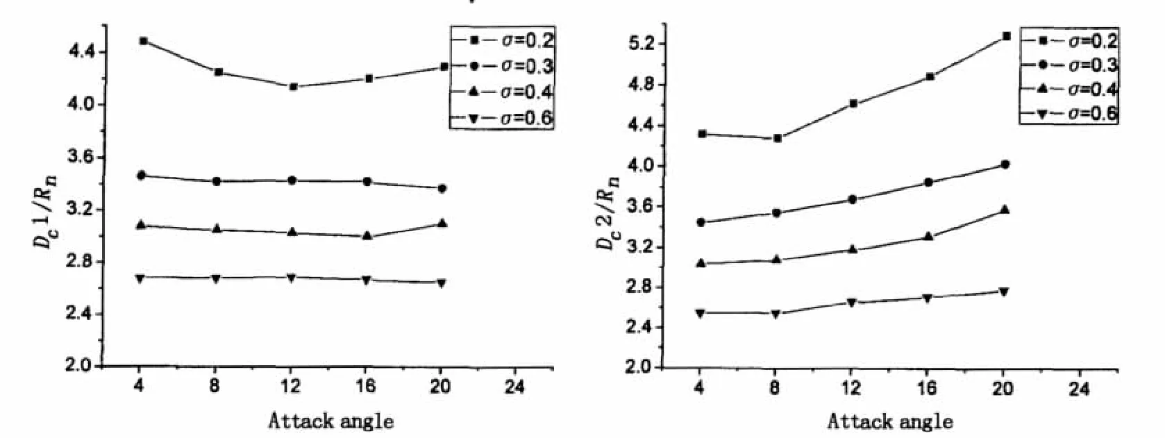
Fig.6 Main diameter dimensions of cavity

Fig.7 Main angle dimensions of cavity
Fig.8 and Fig.9 present the simulated pressure distribution along the pressure-side wall and suction-side wall at different cavitation number and attack,comparing with the experimental results obtained by Quan et al[16].
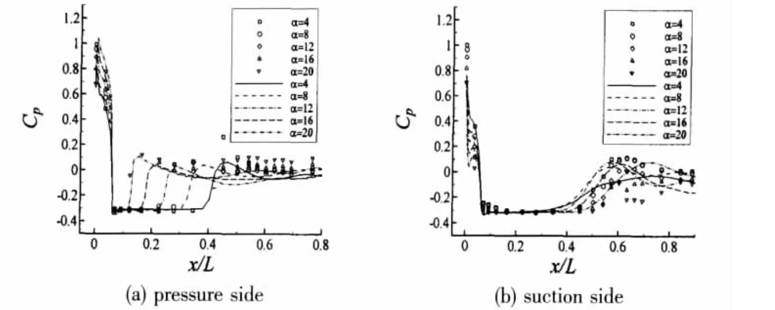
Fig.8 Pressure coefficient distribution at different attacks(σ=0.3)
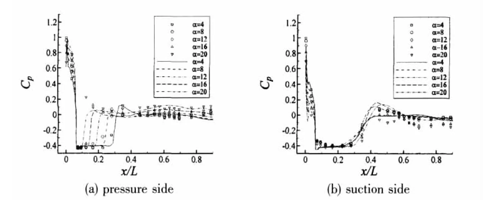
Fig.9 Pressure coefficient distribution at different attacks(σ=0.4)
The computational results generally agree with the experimental data well on cavity length,pressure inside cavity and pressure at cavity inclosure point,etc.What is needed to be concerned,the experimentally measured pressure in all-wet area after the cavity closure,especially on the suction wall at condition of σ=0.3,is confused to some extent.The experimental and the numerical results reveal the following identical pressure distribution characteristics:along the axis of the vehicle,firstly,the pressure reduces intensely from the maximal value at the stagnant point to the saturated vapor pressure p∞at the forepart separating point of cavity.Then,pressure keeps constant of p∞throughout the pressure platform area inside cavity.Finally pressure lifts dramatically across the cavity closure point and then lowers lightly to keep constant value at the following all-wet part of the vehicle wall.
The relations between the pressure platform length and attack present the same laws as what narrated in Fig.5.That is said,the cavity length on pressure side decreases along with the attack more apparently than on suction side.This obvious character is also successfully simulated to be in accordance with experiment.
In real applications,underwater vehicle deviating from its moving direction seriously,namely large attack occurring,may often bear great load or even get damaged.To explain the mechanism of such phenomenon,a circumference integral stress coefficient CFpwas defined as:

Fig.10 presents the distribution of CFpalong vehicle axis for conditions of different attacks.Contrasting with cavity image and pressure distribution,it is obvious that the stress peaks appearing in Fig.10 are caused by asymmetry of cavity on pressure side and suction side.As the pressure behind cavity closure point does not differ greatly for one specific cavitation number when the attack decreases,the peak stresses caused by difference between this pressure and saturated vapor pressure are basically similar.However,when the attack rises,the extent of positive stress widens along with strengthening of cavity asymmetry.
Taking vehicle radius of r=0.25m as example,Tab.1 lists the resultant force on unit length calculated using peak stress.It is obvious to see from the resultant force that the bending moment acting on vehicle body is so large to influence the vehicle or even damage it.

Fig.10 Resultant stress coefficient along vehicle axis(σ=0.3)

Tab.1 Resultant force on unit length at different conditions
Fig.11 presents the relation of lift-force and drag-force coefficients with the attack of vehicle at different cavitation numbers,comparing with that of all-wet flow.

Fig.11 Relation between force coefficients and attack at different cavitation numbers
An important and interesting conclusion was found that,the relation between drag-force coefficient and cavitation number at large-attack condition is absolutely negative to the relation at zero-attack condition.Such result can be explained as follows:
At zero-attack condition,the cavity is axisymmetric,thus drag force is primarily con-tributed by viscous force.Therefore,the smaller the cavitation number is,the longer the vehicle is surrounded by cavity,thus the smaller the drag force is.However,at large-attack conditions,the cavity is asymmetric,thus drag force primarily results from the difference between the pressures on suction side and pressure side.Hence,along with the increment of cavity length on suction side and decrement on pressure side,the pressure difference increases and thus lift force and drag force increase.
4 Conclusions
This paper established a set of HEM based on mathematical models and numerical simulation methods for cavitation,and developed computation code.The authors applied it to research 3-D large-attack cavitating flows over a kind of underwater vehicle.Full field density,pressure and velocity distributions at different cavitation number and different attack were studied systematically.The computed cavity shapes and pressure distributions agree with experiment in general and inflect some detailed cavity characters observed by experiment.The relations of different cavity dimensions to cavity number and attack were investigated to find different variation rules.The integral stress acting along vehicle axis was studied and found that the resultant stress in real flows may be great enough to damage the vehicle.The mechanism was considered to result from asymmetricy of cavity and explained by pressure difference of suction side and pressure side.It was also discovered interestingly that,the drag-force variation trend along with cavitation number at large-attack conditions was absolutely opposite to that at zero-attack condition.
[1]Merkle C L,Feng J,Buelow P E O.Computational modeling of the dynamics of sheet cavitation[C]//3rd Int.Symp.on Cavitation.Grenoble,France,1998:307-313.
[2]Byeong R S,Satoru Y,Xin Y.Application of preconditioning method to gas-liquid two phase flow computations[J].J Fluids Engineering,2004,126(4):605-612.
[3]Wu Lei,Lu Chuanjing,Xue Leiping.An approach in modeling two-dimensional partially cavitating flow[J].Journal of Hydrodynamics,Ser.B,2002,14(1):45-51.
[4]Wu Lei.Numerical simulations of cavitating flows[J].Journal of Hydrodynamics,Ser.B,2003,15(4):125.
[5]Wu Lei,Lu Chuanjing,Li Jie,et al.Numerical simulations of 2D periodic unsteady cavitating flows[J].Journal of Hydrodynamics,Ser.B,2006,18(3):341-344.
[6]Chen Ying,Lu Chuanjing,Wu Lei.Modeling and computation of unsteady turbulent cavitation flows[J].Journal of Hydrodynamics,Ser.B,2006,18(5):559-566.
[7]Kubota A,Kuto H,Yamaguchi H.A new modeling of cavitating flows:A numerical study of unsteady cavitation on a hydrofoil section[J].J Fluid Mech.,1992,240(7):59-96.
[8]Markatos N.Modeling of two-phase transient flow and combustion of granular propellants[J].Int.J Multiphase Flow,1986,12:913-933.
[9]Kunz R,Boger D,Chyczewski T,et al.Multi-phase CFD analysis of natural and ventilated cavitation about submerged bodies[C]//3rd ASME/JSME Joint Fluids Engineering Conference.San Francisco,CA,USA,1999.
[10]Fu Huiping,Lu Chuanjing,Wu Lei.Research on characteristics of flow around cavitating body of revolution[J].Journal of Hydrodynamics,Ser.A,2005,20(1):84-89.(in Chinese)
[11]Chen Ying,Lu Chuanjing,Wu lei.Numerical method for three dimensional cavitating flow of small cavitation number[J].Chinese Journal of Computational Physics,2008,25(2):163-171.(in Chinese)
[12]Singhal A K,Athavale M M,Li Huiying,et al.Mathematical basis and validation of the full cavitation model[J].J Fluid Engineering,2002,124:617-624.
[13]Chen Ying,Lu Chuanjing.A Homogenous-Equilibrium-Model based numerical code for cavitation flows and evaluation by computation cases[J].Journal of Hydrodynamics,Ser.B,2008,20(2):186-194.
[14]Hu Yong,Chen Xin,Lu Chuanjing,et al.Study on the interaction between ventilated cavitating flow and exhausted gas of an underwater vehicle[J].Journal of Hydrodynamics,Ser.A,2008,23(4):438-445.(in Chinese)
[15]Chen Xin,Lu Chuanjing,Li Jie.The wall effect on ventilated cavitating flows in closed cavitation tunnels[J].Journal of Hydrodynamics,Ser.B,2008,20(5):561-566.
[16]Quan Xiaobo,Li Yan,Wei Haipeng,et al.An experiment study on cavitation of underwater vehicle’s surface at large angles of attack[J].Journal of Hydrodynamics,Ser.A,2008,23(6):662-667.(in Chinese)
猜你喜欢
杂志排行
船舶力学的其它文章
- Hydrodynamic Analysis of 3-D Hydrofoil under Free Surface in Time Domain
- Hydroelastic Analysis of SWATH Ship Wave Loads
- Applicability of the Improved Crack Growth Rate Model for a Wide Range of Alloys under Constant Amplitude Load
- Vulnerability Evaluation of Aircraft Guarantee System by Improved Fuzzy Petri Net
- Optimum Design of Cylindrical Shells under External Hydrostatic Pressure
- Analysis of Mechanics During Berthing of Engineering Ships
