Hydroelastic Analysis of SWATH Ship Wave Loads
2010-02-27YEYonglinWUYoushengYOUGuohong
YE Yong-lin,WU You-sheng,YOU Guo-hong
(China Ship Scientific Research Center,Wuxi 214082,China)
1 Introduction
The first Small Waterplane Area Twin Hull(SWATH)ship appeared in 1973.Since its birth,SWATH has been commonly recognized as the type of ship with the best seakeeping performance.Up to now,about 60 SWATH ships have been built up all over the world,including 5 designed and built up in China[1].
In comparison with monohull ships,a SWATH ship has multi-body configurations and more design parameters.This makes its wave load estimations as well as design optimization much more complicated than a monohull ship.In the traditional wave load analysis,the hull is regarded as the rigid body with no structural distortions.Thus the obtained wave loads are acted on the ship structure to analyze the distortions and stresses,while ignoring the influence of structural distortions on the surrounding fluid flow.The hull structure of a SWATH ship looks like an upside down ‘tuning fork’ partly immerged in water,has larger lateral flexibility than a monohull ship,and easily suffers from the prying moment.Hence the traditional wave load analysis method is not sufficient for a SWATH ship.This requires the application of the three-dimensional hydroelasticity theory[2],which combines the structural Finite Element analysis with the potential flow analysis,to form a unified method for describing the fluid-structure interactions and predicting the motions,distortions,strains,stresses,global forces and moments of the ship hull.
The linear 3-D hydroelasticity theory appeared in 1984[2].Later on,the numerical method of solving the equations and boundary conditions with all the forward speed terms of the theory was developed[3],allowing the forward speed effects to be rationally examined in the hydroelastic analysis.In 1997 a second order hydroelasticity theory was proposed[4]to include the nonlinear hydrodynamic actions induced by the large rigid body motions and the variations of the instantaneous wetted surface of the ship hull in the hydroelastic analysis.The corresponding numerical method was developed and applied,for example to a SWATH ship[5]and a large bulk carrier[6].
This paper concentrates on the estimation of wave loads of SWATH ships by employing the linear 3D hydroelasticity theory and the numerical method with forward speed effect.Evidently,for a SWATH ship,the transverse wave loads are the most important for the structural safety[7].Hence in the present paper,only the transverse wave loads are discussed.
2 Hydroelastic analysis of SWATH ships
Under the assumption that the forced vibration amplitude of the structure is small,the dynamic displacement of the structure can be expressed in term of superposition of principal modes of the dry structure:


3 Modal analyses
A SWATH ship of the displacement of 1 100t is taken as an example of the hydroelastic analysis.The principle dimensions of the ship are shown in Tab.1.
The dry hull natural frequencies of theSWATH ship are calculated by FEM software Msc.Patran/Nastran.Due to the port and starboard symmetry,only half of the ship hull needs to be modeled in the FEM analysis(Fig.1),which is of 26 620 nodes and 52 196 elements.

Tab.1 The principle dimensions of the SWATH ship

Fig.1 The FEM model of the port part of the ship
The calculations of the dry modes are separated into two groups of symmetric and antisymmetric respectively by imposing different boundary conditions on the longitudinal crosssection at the center line.The first five dry modes are exhibited in Fig.2.

Fig.2 Mode shapes of the SWATH ship
4 Short-term predictions of wave loads
In short-term predictions,both the waves and the ship responses can be regarded as the steady random processes,and the statistical characteristics of the wave loads can be calculated in terms of linear system transform method of the random process theory.
4.1 Spectrum analysis method
As a random process of narrow-banded normal distribution with zero mean value,the wave may be expressed by the wave spectrum density function Sηη(ω )in frequency-domain,where the wave elevation η(t)satisfies the normal distribution,and the wave amplitude satisfies the Rayleigh distribution.
The ship structure may usually be regarded as a linear system with time independent characteristics,namely as the time invariant system.If the system input is the wave elevation η(t),the structural responses,such as the displacements,stresses and bending moments,etc are denoted as Y(t),which are linear functions of η(t).Their power spectrum densities satisfy the following relation:

where H(ω)is the transfer function of the linear dynamic system, [H(ω)]is the response amplitude operator(RAO).The transfer function H(ω)is the ratio of wave load amplitude to wave height when the ship is in the regular cosine wave of frequency ω.
The response amplitude satisfies the Rayleigh distribution:

where the parameter σ2=Dy=m0can be calculated by the response spectrum:

The statistic output values for the single amplitude are:mean value
4.2 Wave load calculation
If the transverse modal force of the rth mode at the ith node,calculated in the FEM analysis of the dry structure is expressed byand the node coordinate is(x ,y,z),the rthiiiprincipal modes of transverse forceand transverse momentacting at the longitudinal mid-section of the SWATH ship can be expressed as:

where m is the number of modes.N is the total number of nodes located in the longitudinal mid-section.ZNis the height of neutralized axes of the longitudinal mid-section.
The frequency variation of principal coordinates for each mode under the regular wave excitations with unit amplitude can be obtained by solving the hydroelastic linear equations of motion in frequency-domain.The transfer functions of transverse wave loads can be expressed as:

where ωeis the encounter wave frequency,is the rth mode principle coordinate.
4.3 The wave load transfer functions in regular waves
The wave load transfer functions are calculated at 36 wave frequencies,from 0.05Hz to 1.8Hz.The wave height is 1m,wave heading is 90°and the ship velocity is 0.
2 620 panels were used to describe the wetted surface of the port part of the ship hull in the hydroelastic analysis,as shown in Fig.3.

Fig.3 Discretization of the wetted surface of the port part of the SWATH ship

Fig.4 The principal coordinates
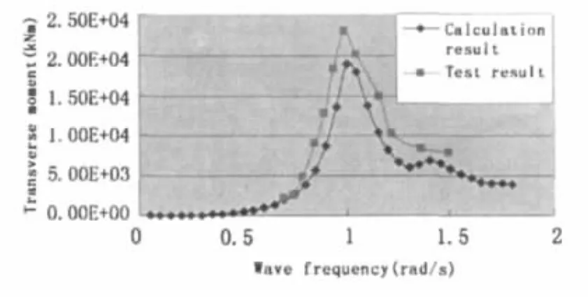
The numerical results of the principal coordinates of the 7th to 11th modes are illustrated in Fig.4,showing that the 7th mode(the symmetrical transverse swaying motion of the lower-hulls and the struts)exhibits the greatest influence on the wave induced structure responses,while the contributions of other modes are rather small.The predictions of the transverse resultant force and moment corresponding to the 7th mode are compared with the model test results in Figs.5 and 6 respectively,showing good agreement.The predicted maximum transverse force and maximum transverse moment are 2.93×10³kN and 1.89×10⁴kNm respectively,all appear at the wave frequency of 1.0 rad/s,but about 9.5%and 18%smaller than the test results.

Fig.5 Transfer function of the transverse force

Fig.6 Transfer function of the transverse moment
4.4 Wave spectrum
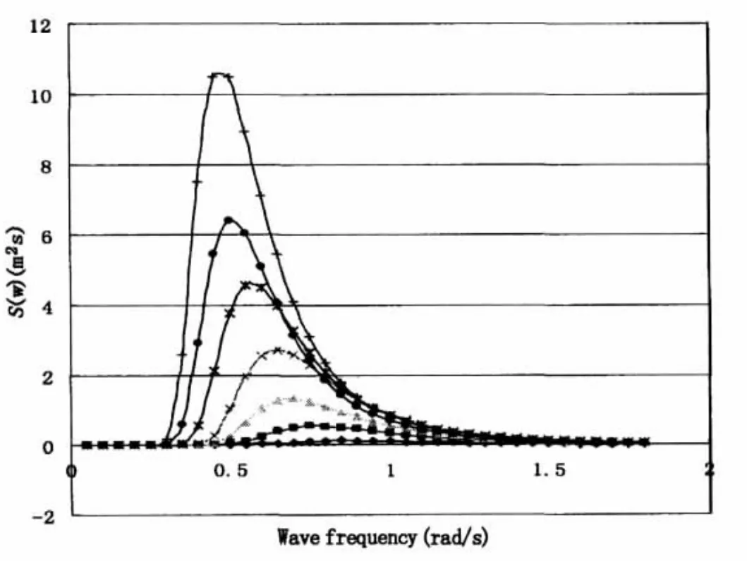
The operation area of the SWATH ship is the coastal zone of China sea,where the sea states may be expressed by the ITTC wave spectrum as follows:

with H1/3being the 1/3 significant wave height and T01the average characteristic wave periods(s).
Fig.7 shows 7 typical wave spectra in the coastal zone of China sea,the corresponding values of H1/3and T01are listed in Tab.2.
4.5 Response spectrum
The predicted significant values of the resultant transverse forces Fy1/3and moments Mx1/3of the SWATH ship with 0 forward speed in beam sea of the sea states represented by the 7 wave spectra are shown in Tab.2.
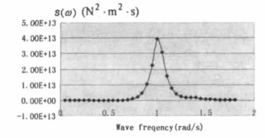
Figs.8 and 9 are respectively the response spectra of the transverse force and moment calculated by Eq.(3)for the sea state of H1/3=1.04 and T1/3=5.79s.

Fig.7 The wave spectrum corresponding to the 7 sea states shown in Tab.2

Tab.2 Transverse wave force and moment in beam sea(v=0)

Fig.8 The spectrum of transverse force(H1/3=1.04m,T01=5.79s)

Fig.9 The spectrum of transverse moment(H1/3=1.04m,T01=5.79s)
5 Design values of the transverse wave loads
The design loads of the SWATH ship are subsequently figured out based on the above mentioned predictions of the significant values of the transverse forces and moments for different wave conditions(for example the significant wave height),however multiplied by the design safety factor.According to the suggestions made by the report of 10th ISSC,the ship design safety factor should not be less than 2.0[8].The experience in marine engineering shows that the characteristic maximum value of the transverse loads Fymaxcould almost be twice of the one-third significant value Fy1/3.Hence,for safety’s sake the design value FyDshould be

5.1 Comparisons with the model test results and other existing data
Fig.10 exhibits the design value of the transverse force,and the comparisons with the model test results of a SWATH ship of 1 100t displacement[9],and other published data[10-12].Tab.3 shows the particulars of the reference ships used for comparison,where the 1 350t SWATH ship has the same ship form as the 1 100t SWATH ship,however with enlarged dimensions.

Fig.10 The predicted design value of the transverse force and the comparisons with the available data

Tab.3 Particulars of the reference ships used for comparisons
5.2 Comparisons with the calculation results by the rules
Several classification societies have produced SWATH ship design rules or guides,such as CCS(2004),LR(2004)and ABS(2000).The calculation methods of transverse design wave loads of SWATH ship proposed by different classification societies actually provide different results.Tab.4 shows the transverse design wave loads of the 1 100t SWATH ship[9]obtained by using the rules of LR,CCS,and ABS.Listing in the table is also the test result of the ship model with scale 1:20,and the result predicted by employing the 3-D hydroelastic analysis method.It shows that the design loads given by the classification society rules are larger than the experimental result by about 52%to 78%.The prediction of the hydroelastic analysis is much closer to the experimental result.

Tab.4 Comparisons of design value of the transverse wave loads(SWATH 1 100)
6 Conclusions
The 3D hydroelastic analysis method is used together with the spectrum analysis procedure to predict the wave load spectra and the design loads of a SWATH ship.The numerical predictions illustrate the feasibility of the hydroelastic analysis method in the assistance of the SWATH ship design.
Acknowledgement
The authors would like to thank Prof.Lin Jiru,Prof.Ni Qijun and Dr.Tian Chao et al for their effort in performing the model test of the SWATH ship,and for creative discussions regarding the reasonable values of the design loads for a SWATH ship.
[1]Wu Yousheng,Ni Qijun,Ge weizhen.Advances in technology of high performance ships in China[J].Journal of Ship Mechanics,2008,12(6):1014-1031.
[2]Price W G,Wu Yousheng.Hydroelasticity of marine structures.Sectional lecture S-10,Proc.of 16th Int.Congress of Theoretical and Applied Mechanics(IUTAM)[C].Lyngby,Denmark,1985:311-337.
[3]Du Shuanxing.A complete frequency domain analysis method of linear three-dimensional hydroelastic responses of floating structure traveling in waves[D].China Ship Scientific Research Center,Wuxi,China,1996.(in Chinese)
[4]Wu Yousheng,Maeda,Hisaaki,Kinoshita,Takeshi.The second order hydrodynamic actions on a flexible body[J].SEISAN-KENKYU of Institute of Industrial Science of Univ.of Tokyo,1997,49(4):8-13,14-19.
[5]Tian Chao,Wu Yousheng.The second-order hydroelastic analysis of a SWATH ship moving in large-amplitude waves[J].Journal of Hydrodynamics,Ser.B,2006,18(6):631-639.
[6]Tian Chao,Wu Yousheng,Chen Yingqiu.Numerical predictions on the hydroelastic responses of a large bulker in waves.Proceedings of the 5th International Conference on Hydroelasticity in Marine Technology[C].University of Southampton,UK,8th-10th Sept.,2009:205-213.
[7]Lin Jiru,Shi Liguo,You Guohong,Qian Jianyu.The method for evaluating the design wave loads on SWATH ship[J].Shipbulding of China,2008,49(3):104-111.
[8]Dai Yishan,Shen Jinwei,Song Jingzheng.Ship wave loads[M].Beijing:National Defense Industry Press,2007:163.
[9]You Guohong,et al.Model test report of the 1 100t SWATH ship[R].CSSRC Technology Report,Wuxi,China,2007.
[10]Fujii H,Kume N,et al.Motion Characteristics of the semi-submerged catamaran-type underwater work test vessel in waves[J].Techn.Rept.of JAMSTEC,1983(11):24-36.
[11]Sikora J P.Design algorithms for primary and secondary loads on SWATH ships[J].Naval Engineers Journal,1995(5):121-127
[12]Sikora J P,Dinsenbacher A L.SWATH structure:Navy research and development applications[J].Marine Technology,1990(7):211-220.
杂志排行
船舶力学的其它文章
- Modeling and Simulation of Cavitating Flow over Underwater Vehicle with Large Angle of Attack
- Hydrodynamic Analysis of 3-D Hydrofoil under Free Surface in Time Domain
- Applicability of the Improved Crack Growth Rate Model for a Wide Range of Alloys under Constant Amplitude Load
- Vulnerability Evaluation of Aircraft Guarantee System by Improved Fuzzy Petri Net
- Optimum Design of Cylindrical Shells under External Hydrostatic Pressure
- Analysis of Mechanics During Berthing of Engineering Ships
