Applicability of the Improved Crack Growth Rate Model for a Wide Range of Alloys under Constant Amplitude Load
2010-02-27CHENFengluoWANGFangCUIWeicheng
CHEN Feng-luo,WANG Fang,CUI Wei-cheng
(China Ship Scientific Research Center,Wuxi 214082,China)


1 Introduction
Metals are the most widely used materials in marine structures such as ships and off-shore platforms which suffer from fluctuating load in service,and the most common failure modes of metal structures is fatigue[1].Metal fatigue has been studied for more than 170 years which originates from Wöhler’s work[2].The accurate fatigue life prediction is very significant to ensure the safety of marine structures and guide economic design and maintenance.Many fatigue life prediction(FLP)methods have been proposed and they can be divided into cumulative fatigue damage(CFD)theory and fatigue crack propagation(FCP)theory which are both in deterministic sense and probabilistic sense.The CFD theory is the traditional theoretical framework for fatigue strength assessment(FSA)and still plays a dominant role in the ship classification rules at the present time.Nevertheless,more and more people have reached a consensus that the methods based on CFD theory suffer from significant theoretical deficiencies which can be overcome by FCP theory based on fracture mechanics.
The earliest theory for predicting the fatigue crack propagation is the linear elastic fracture mechanics(LEFM).And Paris[3]who first introduced LEFM approach expressed fatigue growth rate by using stress intensity factor range ΔK,namely,the so-called Paris-Erdogan crack growth law.Subsequently,hundreds of fatigue crack growth rate models have been developed with advance of fracture mechanics,which can be generalized into single parameter models and double parameter models.One of the most famous single parameters model is Paris equation,however,it is only applicable for middle linear propagation region of the crack growth rate curve and does not consider mean stress effect and load sequence.To take stress ratio effect into account,Elber[4]proposed crack closure concept and effective stress intensity factor range ΔKeff.Later,various improvements taking effective stress intensity factor range ΔKeffas fatigue crack driving force have achieved some successes[5-6].As one of the preferable fatigue crack growth models,the modified constitutive relation developed by McEvily and his coworkers[7]can not only account for the effects of initial crack size and load sequence,but also explain various other phenomena of metal fatigue observed in tests.
Based on McEvily’s model,Cui and Huang[8]have proposed a general constitutive relation for fatigue crack growth.Later,Wang and Cui[9]obtained the extended McEvily model by further improving.Recently,an improved crack growth rate model has been proposed[10],which can cover three regions of fatigue crack growth rate curve and explain more fatigue phenomena observed in tests.In this paper,the improved crack growth rate model is further specified,and its parameters engineering estimation methods under constant amplitude load have been demonstrated for saving time and cost.Finally,the fatigue life predicted results for wide range of alloys such as aluminum alloy,titanium alloy and steel are compared with corresponding experimental data to validate its accuracy and applicability.
2 The improved crack growth rate model
Metal fatigue has been studied for more than 170 years,and a big step forward was made by Paris and co-workers[3]who defined the cyclic stress intensity factor range ΔK as the fatigue crack driving force and equated fatigue crack growth rate to ΔK as:

Later,people found that the crack growth rate curve is not linear for all ranges of ΔK but in sigmoid shape,which can be subdivided into three regions,namely,crack initiation and threshold region,stable crack growth region and unstable fracture region.Furthermore,in order to explain the effects of load ratio on fatigue crack growth,Elber[4]introduced the concepts of crack closure and the effective stress intensity factor as ΔKeff.Based on that,McEvily et al[7]recommended the following constitutive relation for fatigue crack growth analysis:

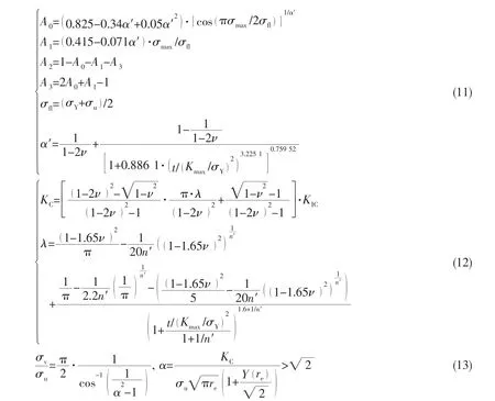
This modified constitutive relation was found to be able to account for observed various fatigue phenomena[7,11]and valid from physically small crack to long crack regimes[12].But McEvily’s model is only applicable for near threshold region and valid for elastic-perfectlyplastic materials.The limitations are broken through the efforts of Cui and Huang[8].They further generalized McEvily model by:(1)introducing an unstable fracture condition into the crack growth rate curve to cover the unstable growth region;(2)defining a ‘virtual strength’ σvto replace the yield stress in Eq.4.Thus the generalized constitutive relation for fatigue crack growth of metals can be expressed as follows:

The ‘virtual strength’ σv,which can be determined from the following equation:

And the solution of Eq.6 is

The virtual strength of the material may represent the material strength at limit of‘per-fect’condition(re=0 )while the actual ultimate strength of the material (σu)represents the strength under the condition that the defect size is equal to the inherent flaw length (re>0 ),a minimum crack size for engineering metals.
However,it is shown in Li[12]that McEvily model with the fixed slope of 2 is not in a greement with many experimental results.Thus Wang and Cui[9]proposed a further extended model based on the work of McEvily[7]and Cui[8].In this model,the parameter m is adopted to represent the slope of the fatigue crack growth rate curve for different materials as variable.And bothΔKeffthandKopmaxare expressed as the functions of the stress ratio R,which are usually derived from their corresponding values of zero stress ratio,i.e.ΔKeffth0andKopmax0.
Recently,an improved crack growth model has been developed[10],among which the assumptions as follows will be added:(1)The value of KCin the crack growth model varies with crack length;(2)The unstable fracture occurs when the stress intensity factor with a certain crack length reaches its corresponding KC;(3)The stress intensity factor at the opening level will also change with crack length by modifying the crack tip stress/strain constraint factor.
The parameterKopmax0,defined as the maximum stress intensity factor at the opening level for a macroscopic crack,is introduced in view of this and has been adopted in the extended McEvily model proposed in our former work[8-9].However,the measurement method of the parameterKopmax0is still not expatiated very clearly in relevant reference.It is even not a material constant,as the assumption of its independence of stress intensity factor rangeΔKlevel may not be always proved valid[14]and it should be strongly dependent on the stress range[15].In order to less the uncertainty resulting from the measurement of this parameter,the itemΔKopof defined as the stress intensity factor range at the opening level andKopmax0introduced in modified McEvily mode[14]will be replaced by Newman’s function[16-17]in the improved crack growth rate model.The general constitutive relation in the improved crack growth rate model will be written in the following form,

where,


It can be noticed that Kmax,fopand KCare all the functions of crack length a.
3 The engineering approach to estimate model parameters
The improved crack growth rate model involves many parameters to be determined.Its application will be restricted if all model parameters are determined by fatigue crack propagation tests which are both time consuming and cost expensive,especially when crack growth curves under different load ratios are required in practice.In order to overcome this difficulty,the preliminary estimation methods for the model parameters have been introduced[10,18,20],but need further specification and validation.
Here,it is supposed that we can only obtain the fatigue crack growth rate curve of an alloy under a certain stress ratio,which should cover the whole process of fatigue crack propagation,namely,threshold region,middle linear propagation region and unstable propagation region.Then the method to obtain all model parameters and predict corresponding crack growth rate curves under other load ratios using our model will be necessary.
For a certain type of cracked specimen,from the expression of the stress intensity factor range in linear form,we can transform the data series of ΔK ( linea )rversus da/dN to that of a versus da/dN.An average equivalent inherent flaw length of the material,re,is assumed to be a constant of 1.0×10⁻⁶m[19].At the same time,the value of n will be kept as a constant of 6.0 according to the analysis in Ref.[20].Therefore,four critical parameters remain to be determined,namely,KIC,ΔKeffth,A and m.
3.1 Estimation of the value of KICthrough crack growth rate curve
Typically,KICshould be obtained by the fracture toughness test but that is time consuming and cost expensive.In this paper,the value of KICwill be estimated through the crack growth rate curve according to the assumption on unstable crack growth condition in our model.
Supposing one crack growth rate curve ΔK ( linear ) versus da/dN is obtained by test,such as that under R=0.1.Then parameters ΔKf0.1(linear )and ΔKth0.1(linear )can be known.And ΔKf0.1(linear )can be used to estimate the value of KICby solving the following equation to obtain critical crack length af0.1,

Then Kmaxf0.1(no nlinea r)can be obtained accordingly by substituting af0.1into Eq.9.
It is assumed in the model that unstable crack growth occurs when Kmax(no nlinear)reaches KCand KCis a variable changing with crack length according to Eq.12.Substituting both Kmaxand KCby the value of Kmaxf0.1(no nlinear),then the value of KICcan be obtained.
3.2 Estimation of the value of ΔKeffththrough crack growth rate curve
An improved equation was proposed for prediction of the effect of load ratio on fatigue threshold ΔKth(linea )r from a comprehensive analysis on different kinds of materials[21].The equation is written in a segmented function for three regions of load ratio as follows:

where β and β1are material constants.And,for quick analysis,the values of the two quantities can be set as the following constants for aluminum and steel respectively[21]:

Eq.15 is recommended here as the function linking the values of ΔKth(linear )of a wide range of load ratios.
When ΔKth(linear )(R)is obtained,the value of ath(R)can be easily known,and consequently the value of ΔKeffth(R )will be calculated by the following equation,

3.3 Estimation of A and m
When all the parameters explained above have been determined by experimental or empirical methods,the values of A and m can be determined through the curve fitting method based on the experimental crack growth data under a certain load ratio,e.g.R=0.1 in this case through the following method.
Change the form of the model to:

In the crack growth rate curve under a certain R,the relationship betweenand M can be obtained.Consequently,a curve betweenlogand logM can be drawn.Aslogthe values of parameters A and m can then be determined by linear curve fitting.The values of KIC,ΔKeffth(R ),A and m can be used to predict the crack growth rate curves under other different load ratios.
4 Applicability for a wide range of alloys
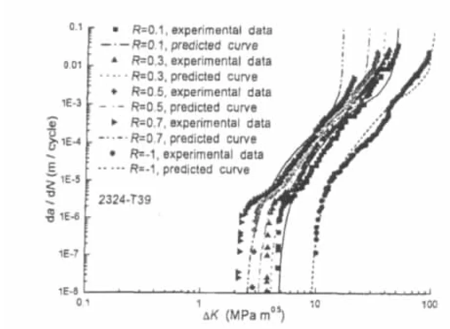
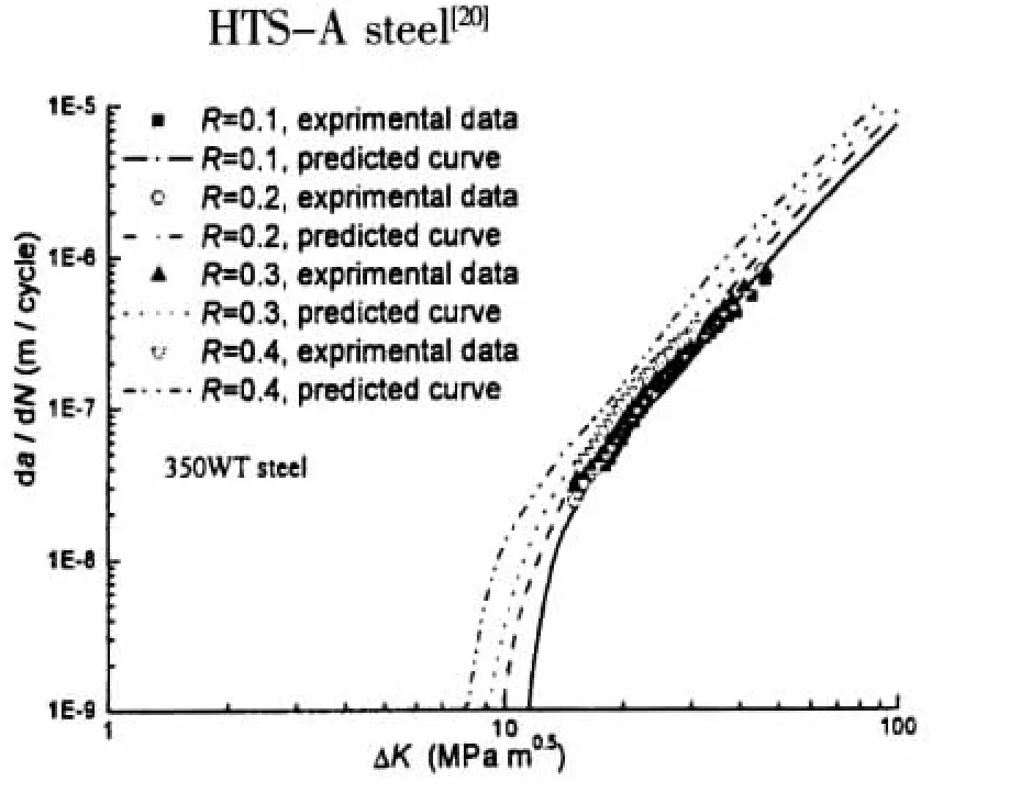
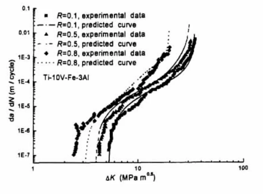
The approximate estimation approach of model parameters introduced above will be validated in this part by a wide range of alloys,which include aluminum alloy[22-24],titanium alloy[28],and steel[20,25-26].Detailed information on test conditions can be referred in references but engineering estimation methods[29-32]used for those test parameters are not described in references.In all examples,the model parameters are derived from experimental data under stress ratio R=0.1 and then used to estimate the crack growth rate curves under other stress ratios.The comparisons between test data and prediction curves are illustrated in Figs.1-10,which show that the prediction curves agree well with test data and the approximate estimation approach is accordingly validated.Tab.1 lists values of A and m for different material analyzed in this paper and could provide guidance in future’s analyses for corresponding materials.

Fig.1 Comparison between predicted crack growth rate curves and test data of 2324-T39 aluminum alloy[22]

Fig.2 Comparison between predicted crack growth rate curves and test data of 6013-T651 aluminum alloy[22]

Fig.3 Comparison between predicted crack growth rate curves and test data of 7055-T7511 aluminum alloy[22]

Fig.4 Comparison between predicted crack growth rate curves and test data of 7075-T6 aluminum alloy[23]

Fig.5 Comparison between predicted crack growth rate curves and test data of 7075-T651 aluminum alloy[24]

Fig.6 Comparison between predicted crack growth rate curves and test data of HTS-A steel[20]

Fig.7 Comparison between predicted crack growth rate curves and test data of 300M steel[25]

Fig.8 Comparison between predicted crack growth rate curves and test data of 350WT steel[26]

Fig.9 Comparison between predicted crack growth rate curves and test data of CrMoV[27]

Fig.10 Comparison between predicted crack growth rate curves and test data of Ti-10V-Fe-3Al[28]

Tab.1 Value of A and m for different materials
5 Summary and conclusions
Currently,fatigue crack propagation theory has been realized to be more promising in the fatigue life prediction of marine structures.Hundreds of fatigue crack growth rate models with good performance are developed along with a good understanding of metal fatigue mechanisms.However,it is time consuming and cost expensive by test to determine many parameters in these models,which restricts theirs use in practical engineering application.
Recently,an improved crack growth rate model based on McEvily’s model has been proposed,which can consider more factors and explain more fatigue phenomena.In this paper,the introduction of the improved crack growth rate model is carried out,and model parameters estimate methods are specified.Finally,validation of the improved crack growth rate model for a wide range of alloys under constant amplitude load is executed.
From above analysis and investigation,the following conclusions can be obtained:
(1)By comparisons between prediction curves and test data,it is shown that the improved crack growth rate model has good accuracy and wide applicability to predict fatigue crack growth rate curve for alloys under constant amplitude load.
(2)The model parameters engineering estimate methods are simple and efficient,which can obtain satisfactory prediction results of the crack growth rate curves.
(3)By adopting the improved crack growth model and its parameters estimate methods can save amounts of fatigue tests which are time consuming and cost expensive as only one crack growth rate curve under a certain stress ratio is needed.
(4)As load sequence has not been included in this paper,corresponding research based on the improved model will be exhibited in our future’s research.
[1]Cui W C.A state-of-the-art review on fatigue life prediction methods for metal structures[J].Journal of Marine Science and Technology,2002,7(1):43-56.
[2]Schutz W.A history of fatigue[J].Engineering Fracture Mechanics,1996,54(2):263-300.
[3]Paris P C,Erdogan F.A critical analysis of crack propagation laws[J].J Basic Eng.,1963,85:528-534.
[4]Elber W.Fatigue crack closure under cyclic tension[J].Engineering Fracture Mechanics,1970,2:37-45.
[5]Newman Jr J C.The merging of fatigue and fracture mechanics concepts:A historical perspective[J].Progress in Aerospace Sciences,1998,34:347-390.
[6]Lee S Y,Song J H.Crack closure and growth behavior of physically short fatigue cracks under random loading[J].Engng Fract Mech,2000,66(3):321-346.
[7]McEvily A J,Bao H,Ishihara S.A modified constitutive relation for fatigue crack growth[C]//Fatigue’99:Proceedings of the Seventh International Fatigue Congress.Wu X R,Wang Z G,editors.Beijing,China:Higher Education Press,1999:329-336.
[8]Cui W C,Huang X P.A general constitutive relation for fatigue crack growth analysis of metal structures[J].Acta.Metall.Sinica.,2003,16:342-354.
[9]Wang Y F,Cui W C,Wu X Y,Wang F,Huang X P.The extended McEvily model for fatigue crack growth analysis of metal structures[J].Int.J Fatigue,2008,30:1851-1860.
[10]Wang F,Cui W C.Approximate method to determine the model parameters in a new crack growth rate model[J].Marine Structures,2009,22(4):744-757.
[11]Ishihara S,McEvily A J.A coaxing effect in the small fatigue crack growth regime[J].Scripta Mater,1999,40:617-622.
[12]Sadananda K,Vasudevan A K,Holtz R L.Extension of the unified approach to fatigue crack growth to environmental interactions[J].Int J Fatigue,2001,23:277-286.
[13]Li X Y,Cui W C,Zhang W M.A modified constitutive relation fatigue crack growth[J].J Ship Mech,2006,10(1):54-61.(in Chinese)
[14]Ishihara S,McEvily A J.Analysis of short fatigue crack growth in cast aluminum alloys[J].Int J Fatigue,2002,24:1169-1174.
[15]de Matos P F P,McEvily A J,Moreira P M G P,de Castro P M S T.Analysis of the effect of cold-working of rivet holes on the fatigue life of an aluminum alloy[J].Int J Fatigue,2007,29:575-586.
[16]Newman Jr J C.Crack opening stress equation for fatigue crack growth[J].Int J Fatigue,1984,24(3):131-135.
[17]Newman Jr J C,Crews J H,Bigelow C A,Dawicke D S.Variations of a global constraint factor in cracked bodies under tension and bending loads[J].ASTM STP,1995,1224:21-42.
[18]Wang F,Cui W C.Effect of three dimensional stress state on unstable fracture condition and crack opening level in a new crack growth model[J].Acta Metall Sinica,2010,1:41-49.
[19]Zhou C,Cui W C.Determination of fatigue crack growth rate using existing data[J].Shipbuild.of China,2003,44:74-79.(in Chinese)
[20]Wang F,Chen F L,Cui W C.Applicability of the improved crack growth rate model and its parameters estimation method[J].Journal of Ship Mechanics,2010,14(3):252-262.
[21]Huang X P,Moan T.Improved modeling of the effect of R-ratio on crack growth rate[J].Int J Fatigue,2007,29:591-602.
[22]Paris P C,Tada H,Donald J K.Service load fatigue damage-a historical perspective[J].Int J Fatigue,1999,21:S35-46.
[23]Newman Jr J C,Phillips E P,Everett R A.Fatigue analyses under constant and variable amplitude loading using smallcrack theory[J].NASA/TM-1999-209329,ARL-TR-2001.
[24]Zhao T W,Zhang J X,Jiang Y Y.A study of fatigue crack growth of 7075-T651 aluminum alloy[J].Int J Fatigue,2008,30:1169-1180.
[25]Dinda S,Kujawski D.Correlation and prediction of fatigue crack growth for different R-ratios using Kmaxand ΔK+parameters[J].Eng Fract Mech,2004,71:1779-1790.
[26]Taheria F,Traskb D,Peggc N.Experimental and analytical investigation of fatigue characteristics of 350WT steel under constant and variable amplitude loadings[J].Marine Structures,2003,16:69-91.
[27]Bulloch J H.Near threshold fatigue crack propagation behavior of CrMoV turbine steel[J].Theor Appl Fract Mech,1995,23:89-101.
[28]Jha S K,Ravichandran K S.Effect of mean stress(stress ratio)and aging on fatigue-crack growth in a metastable beta titanium alloy[J].Ti-10V-2Fe-3Al.Metall Mater Trans,2000,3:703-714.
[29]Farahmand B,Nikbin K.Predicting fracture and fatigue crack growth properties using tensile properties[J].Engineering Fracture Mechanics,2008,75:2144-2155.
[30]Oh H K.Determination of fracture toughness by means of the uniaxial tensile test[J].Journal of Materials Processing Technology,1995,54:372-374.
[31]Kang J Y,Choi B I,Lee H J.Application of artificial neural network for predicting plain strain fracture toughness using tensile test results[J].Fatigue Frac Engng Mater Struct,2006,29:321-329.
[32]Farahmand B,Nikbin K.Predicting fracture and fatigue crack growth properties using tensile properties[J].Engineering Fracture Mechanics,2008,75:2144-2155.
杂志排行
船舶力学的其它文章
- Modeling and Simulation of Cavitating Flow over Underwater Vehicle with Large Angle of Attack
- Hydrodynamic Analysis of 3-D Hydrofoil under Free Surface in Time Domain
- Hydroelastic Analysis of SWATH Ship Wave Loads
- Vulnerability Evaluation of Aircraft Guarantee System by Improved Fuzzy Petri Net
- Optimum Design of Cylindrical Shells under External Hydrostatic Pressure
- Analysis of Mechanics During Berthing of Engineering Ships
