Effects of Surface Etch Hole Fault on the Velocity Field inMicrochannel Reactors*
2009-05-15YOUXueyi尤学一andLIShenghua李胜华
YOU Xueyi (尤学一)and LI Shenghua (李胜华)
Effects of Surface Etch Hole Fault on the Velocity Field inMicrochannel Reactors*
YOU Xueyi (尤学一)1,**and LI Shenghua (李胜华)2
1School of Environmental Science and Engineering, Tianjin University, Tianjin 300072, China2School of Chemical Engineering, Tianjin University, Tianjin 300072, China
Microchannel reactors are commonly used in micro-chemical technology. The performance of microreactors is greatly affected by the velocity field in the microchannel. The flow field is disturbed by the cylindrical etch holes caused by air dust on the microchannel surface during its processing procedure. In this approach, a two-dimensional computational fluid dynamics (CFD) model is put forward to study the effect of etch holes on flow field. The influenced area of single or two concave etch holes is studied for the case of laminar flow. The hole diameter, the Reynolds number and the distance between the center of holes are found to have influences on the flow field. Numerical results indicate that the effects of etch hole on the flow field should be evaluated and the way of choosing the economic class of cleanroom for microreactor manufacture is presented.
microchannel, processing faults, etch holes, computational fluid dynamics, velocity field
1 INTRODUCTION
In recent years, the sustained development of microfluidic devices and their potential applications in a variety of fields, particularly those associated with the so called Micro-Electro-Mechanical-Systems (MEMS) have led to interests in the problem of fluid flow under microscopic confinement [1-3]. Microchemical systemsevolve from microelectromechanical systems as miniaturized systems with dimensions in the range of a few microns to hundreds of microns [4]. They combine fluid handling, reaction and separation capabilities with electronic sensing and actuation [5-10].
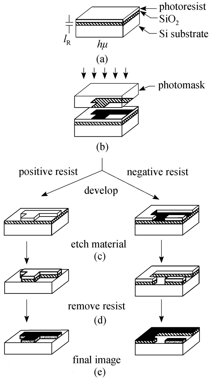
Figure 1 Formation of images after developing positive and negative resists [12]
Fabrication methods for microchemical systems encompass a wide range of materials and microfabrication methods. Forschnungszentrum Karlsruhe and the Institute for Microtechnology Mainz (IMM) have been the primary drivers of multichannel microreactors, micromixers, and micro-heat-exchangers fabricated in metal by use of lithography, electroplating, and molding [5]. Similar devices have been fabricated using microelectrodischarge machining (IEDM) techniques. Reactors have also been fabricated in polymers by microinjection molding, and embossing techniques [11].
One common way to make microreactors is the combined processes of lithography and wet or dry etching. The term lithography originally was coined to describe printing technology. As used here, it refers to a process that uses visible light or other form of radiation to selectively expose and imprint a micron- or submicron-dimension pattern on the sensitized surface of an object. The pattern of microreactor in the resist layer then can be transferred to the underlying substrate by etch or buildup processes. The basic steps of formation of images after developing positive and negative resists are shown in Fig. 1. By using a pattern transfer element that is a transparent elastomer, usually poly(dimethylsiloxane) (PDMS), a pattern of microreactor is embossed on its substrate [13, 14]. The common feature in these techniques is the PDMS is suitable for aqueous systems, but it swells in many organic solvents and has limited temperature stability. Therefore, PDMS-based microreaction components have been used primarily in biological applications, including fluid mixers and electrophoresis. Nevertheless, when combined with other polymers, electroplating of metals and molding of ceramics, the rapid prototyping advantages have considerable applications in microreaction technology [15].
The microreactor defect-related yield losses are primarily a result of the cleanroom environment and the lithography process. Defects are caused by dust particles in the cleanroom, mask defects left over from the mask fabrication process, imperfections in the glass used as a mask substrate, and photoresist particles that are transferred from wafers to masks through direct physical contact. During the high resolution lithographic process, the dust particles in the air or on the mask surface project the shape of particle on the mask pattern. Then the shape of dust on the mask pattern is transferred to the resist layer and casts the process faults on the channel surface of microreactor with cylindrical etch hole along the etch direction after the wet or dry etching process. Although the cleanroom is no longer the dominant source of defects after the early 90 s, the cleanroom of suitable class for microreactor manufacture is required to reduce the very expensive operation cost. Furthermore, the evaluation of microreactor with surface hole faults is also urgently needed.
To the best of author’s knowledge, no report is published on the effects of such processing faults on the quality of microreactors and the choice of cleanroom. A numerical approach concerning the above two requirements is presented here. The results are expected to give suggestions on evaluating the surface hole faults and choosing the economic class of cleanroom for microreactor manufacture.
2 NUMERICAL MODEL
The continuum theory without applying any wall modifications, such as slip boundary [16, 17], apparent viscosity [18, 19], electric double layer [20, 21],., is well considered to be valid for small Kundsen number (≤0.001) flow [1]. In general, the distance between the molecules of liquid is in the order of a few angstroms so that for a microchannel with the characteristic length in the order of micron or larger satisfies the condition≤0.001, which means it is unnecessary to consider any microscale modifications for the flow in such microchannels. In micro-chemical technology, the characteristic length of microchannel reactor is almost in the above range.
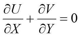
For a microchannel with rectangular cross-section, the liquid is supposed to flow from left to right along the microchannel. The etch hole is casted on the up or below wall. The length of etch hole is the distance between the side walls (the width of microchannel). For a long width (the ratio of width to height is larger than 4) channel considered here, the effects of side walls can be neglected and the three-dimensional problem is approximated as a two-dimensional one by using the mean velocity between side walls. In this case, the velocity profile is assumed to be parabolic in the channel, where the zero velocity is at the up and below walls and the maximum velocity is at the channel center.



3 RESULTS

For single hole case, it is found that the hole has the largest influenced area when the centre of the circle (hole) is located on the plane of microchannel surface. This worst case is considered in the following approach.
3.1 Single hole case
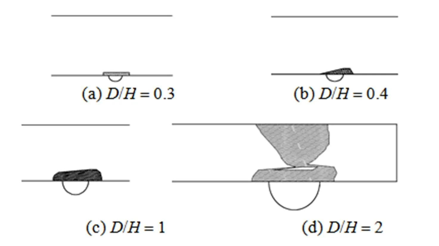
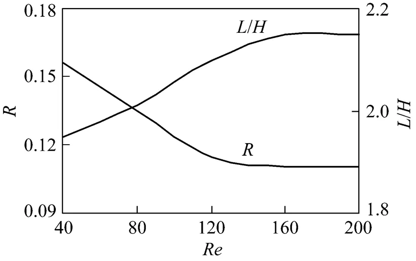
Figure 2 shows the influenced areawith respect to the nondimensional hole diameter/. Flow direction is from left to right, and the centre of the hole is located on the microchannel wall. As the hole diameter increases, the influenced area becomes large. When the nondimensional hole diameter/is equal to 2, the influenced area is full of the whole cross section of the microchannel. Fig. 3 shows the influenced area ratioand the nondimensional maximum influenced length/with respect to/. It is found that theand/almost depend linearly on/and thevalue is less than 5% when the/is less than 0.4.



3.2 Two holes case
The probability of process fault with single etch hole is high. The appearance of two etch holes close to each other may seldom happen. For more than two close etch holes, it hardly occurs. Then, the process fault with more than two etch holes is not discussed here. For the case of two or more etch holes far from each other, the interaction between holes can be neglected and it is equivalent to the case of isolated holes.
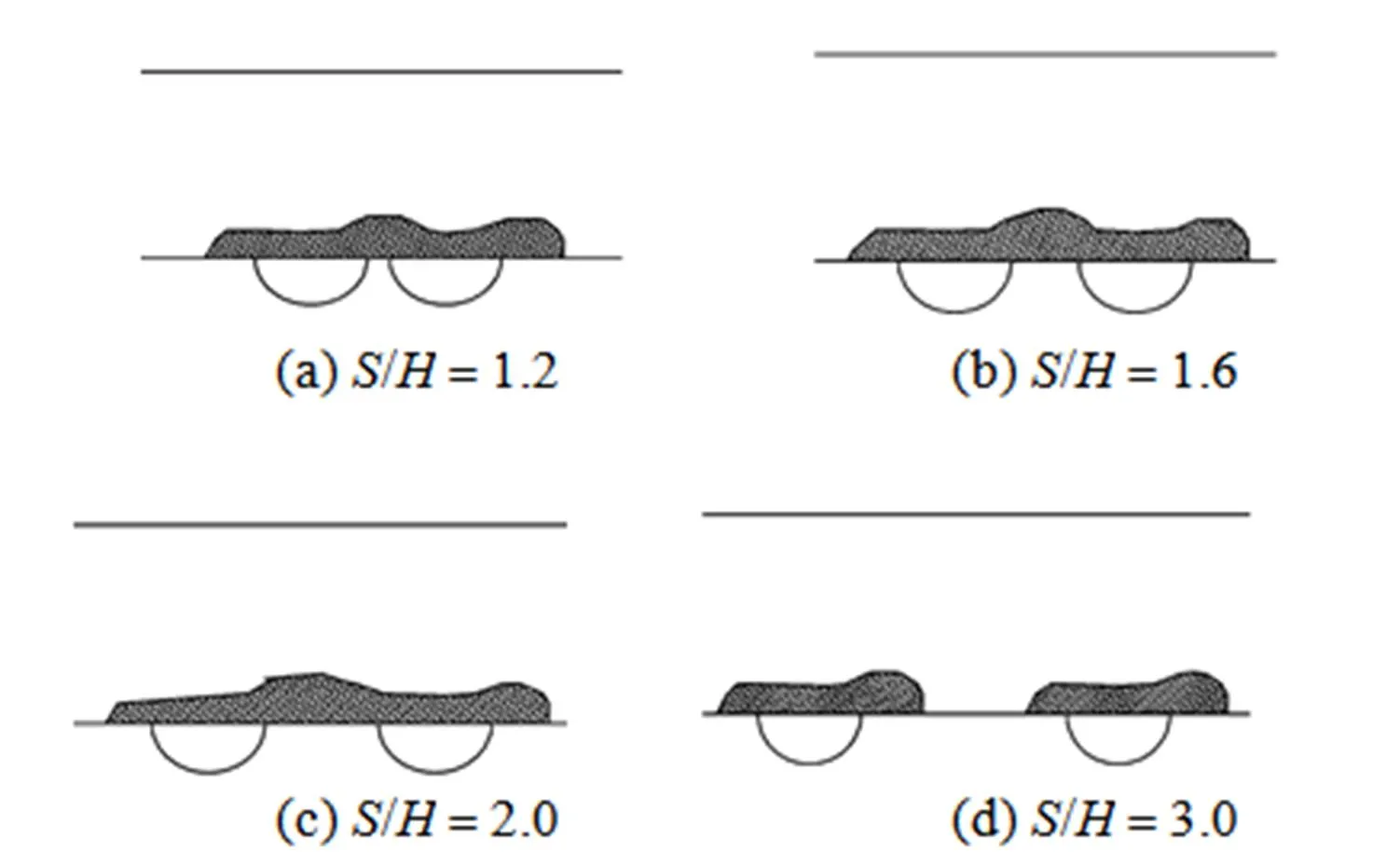


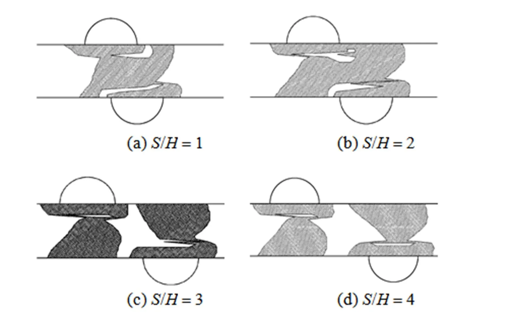


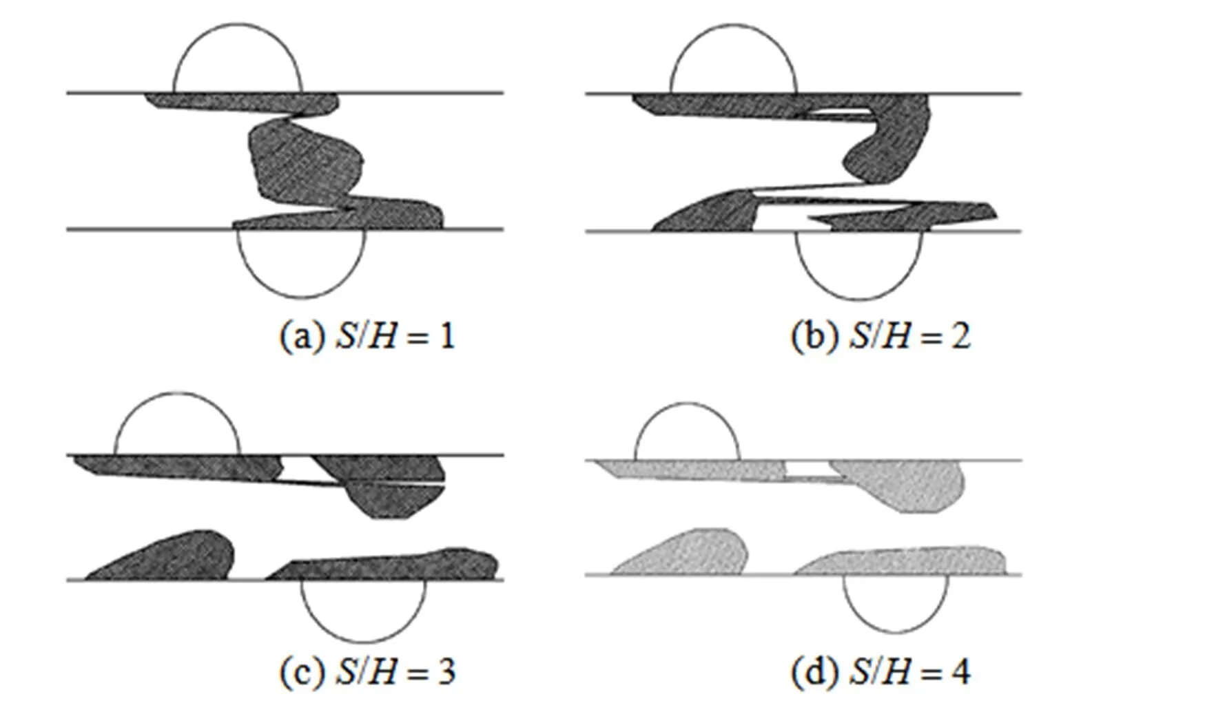


From the above results of single and two etch holes, it can be summarized as the following conclusions.
(1) For single hole, the influenced area ratiois reduced with the increase ofnumber. It becomes less dependent onnumber at largevalue.
(2) The influenced area ratiois increased with the increase of nondimensional number/for single hole. Theis almost linearly dependent on the/. At/less than 0.4, theis less than 5%.

4 DISCUSSIONS
A 2-D model adopted in the present approach serves a very good approximation for the microchannel with large ratio of width and height. In the other ratio of width and height case, the flow in microchannel should be simulated by a 3-D model. This means the effects of two channel side-walls on the flow field must be taken into account. The fluid velocity closed to the side-wall is reduced. It is reasonable to deduce by Fig. 3 that the ratio influenced area of the etch hole is decreased by considering the effect of side-wall. Thus, the effects of etch hole on the real 3-D flow field is smaller than those of the simplified 2-D flow field described above. In addition, the calculation of 3-D flow is much time-consuming. Considering the purpose of present approach is to estimate the effects of possible etch hole on the microchannel flow in order to choose the suitable cleanroom for chip manufacture, it is not necessary to get the exact effects of etch hole. That is why a simple 2-D flow model is adopted to predict the effects of etch hole. Our results are conservative comparing to those of the real case, and they show a very good prediction.
The evaluation of the usefulness of microreactor with hole fault on microchannel surface can be considered in this way. For example, if the nondimensional dust diameter/is less than 0.4 and theis less than 5%, the effects of etch holes on the flow field are neglected for engineering application. From Table 1, it is known that using the class 3 cleanroom to make the microchannel with height of 125 μm is suitable. For this case, only the dust with diameter larger than 25 μm have influences on the flow filed (>5%). According to the cleanroom standard, only few dusts are with diameter larger than 25 μm,.. 300 particles per cubic meter. This means few opportunities to have etch holes on the microchannel surface. On the other hand, it may face much high probability of etch holes troubles when choosing the cleanroom of class 4 and much high operation costs when choosing the cleanroom of class 2.
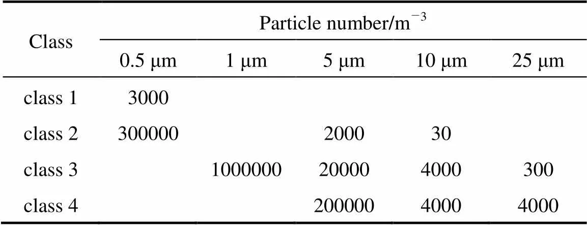
Table 1 BS 5295 cleanroom standards [22]
5 CONCLUSIONS
The flow field changed by the concave etch holes on the microchannel surface is studied. The hole diameter, the Reynolds number and the distance between the center of holes are found to have influences on the flow field. Numerical results indicate that the effects of etch holes on the flow field should be considered and the way of choosing a suitable class of cleanroom is presented. The approach is useful to evaluate the usefulness of microreactor with the etch holes and to choose the class of cleanroom for microreactor manufacture.
NOMENCLATURE
influenced area
echo hole diameter
half channel height
Kundsen number
max streamwise influenced length
dimensionless pressure
pressure
influenced area ratio
Reynolds number
hole center horizontal distance
0streamwise mean velocity
,dimensionless velocity
,velocity
,dimensionless coordinates
,coordinates
viscosity
density
Subscripts
h hole surface microchannel velocity
0 smooth surface microchannel velocity
1 Gad-el-Hak, M., “The fluid mechanics of microdevices-the freeman scholar lecture”,.., 121, 5-33 (1999).
2 Stone, H.A., Stroock, A.D., Ajdari, A., “Engineering flows in small devices: Microfluidics toward a lab-on-a-chip”,..., 36, 381-411 (2004).
3 Squires, T.M., Quake, S.R., “Microfluidics: Fluid physics at the nanoliter scale”,..., 77, 977-1026 (2005).
4 MacInnes, J.M., “Computation of reacting electrokinetic fow in microchannel geometries”,..., 57, 4539-4558 (2002).
5 Ehrfeld, W., Hessel, V., Loewe, H., Microreactors—New Technology for Modern Chemistry, Wiley-VCH Publisher, New York (2000).
6 Chen, G.W., Yue, J., Yuan, Q., “Gas-liquid microreaction technology: Recent developments and future challenges”,...., 16 (5), 663-669 (2008).
7 Shen, J., Zhao, Y.C., Chen, G.W., Yuan, Q., “Investigation of nitration processes of iso-octanol with mixed acid in a microreactor”,...., 17 (3), 412-418 (2009).
8 Sato, K., Hibara, A., Tokeshi, M., Hisamoto, H., Kitamori, T., “Microchip-based chemical and biochemical analysis systems”,.., 55, 379-391 (2003).
9 Pennemann, H., Hessel, V., Loewe, H., “Chemical microprocess technology—From laboratory-scale to production”,..., 59, 4789-4794 (2004).
10 Chan, T.Y., Priestman, G.H., MacInnes, J.M., Allen, R.W.K., “Development of a micro-channel contactor–separator for immiscible liquids”,...., 86, 65-74 (2008).
11 Gardner, J.W., Varadan, V.K., Awadelkarim, O.O., Microsensors, MEMS, and Smart Devices, Tsinghua Univ. Press, Beijing (2004).
12 Sze, S.M., Semiconductor Devices: Physics and Technology, Wiley & Sons, New York (1985).
13 Xia, Y.N., Whitesides, G.M., “Soft lithography”,..., 28, 153-184 (1998).
14 Xia, Y.N., Whitesides, G.M., “Soft lithography”,, 37 (5), 551-575 (1998).
15 Jackman, R.J., Floyd, T.M., Schmidt, M.A., Jensen, K.F., “Development of methods for on-line chemical detection with liquid-phase microchemical reactors using conventional and unconventional techniques”, In: Micro Total Analysis Systems 2000, van den Berg, A., Olthuis, W., Bergveld, P., eds., Kluwer Academic Publishers, Dordrecht, 155-158 (2000).
16 Tretheway, D.C., Meinhart, C.D., “Apparent fluid slip at hydrophobic microchannel walls”,., 14, L9-L12 (2002).
17 Pfahler, J., Harley, J., Bau, H., Zemel, J., “Gas and liquid flow in small channels, micromechanical sensors, actuators and systems”. In: Winter Meeting of ASME: Micromechanical Sensors, Actuators and Systems, ASME, Atlanta, 32, 49-60 (1991).
18 You, X.Y., Zheng, J.R., Jing, Q., “Effects of boundary slip and apparent viscosity on the stability of microchannel flow”,, 71, 99-106 (2007).
19 You, X.Y., Zheng, X.J., Zheng, J.R., “Molecular theory of liquid apparent viscosity in microchannels”,., 56, 2323-2329 (2007).
20 Li, D.Q., Electrokinetics in Microfluidics, Elsevier Publisher, Amsterdam (2004).
21 Yang, C., Li, D., “Analysis of electrokinetic effects on the liquid flow in rectangular microchannels”,, 143 (2-3), 339-353 (1998).
22 Whyte, W., Cleanroom Design, 2nd ed., John Wiley & Sons, West Sussex (1999).
2009-02-24,
2009-09-18.
the National Natural Science Foundation of China (20676093).
** To whom correspondence should be addressed. E-mail: xyyou@tju.edu.cn
杂志排行
Chinese Journal of Chemical Engineering的其它文章
- Study on the Flow Field around Two Parallel Moving Bubbles andInteraction Between Bubbles Rising in CMC Solutions by PIV*
- Kinetic Rate Constant of Liquid Drainage from Colloidal Gas Aphrons*
- β-Diketones at Water/Supercritical CO2 Interface: A MolecularDynamics Simulation*
- Analysis of Sucrose Esters with Long Acyl Chain by Coupling ofHPLC-ELSD with ESI-MS System*
- Adsorptive Removal of Copper Ions from Aqueous Solution UsingCross-linked Magnetic Chitosan Beads
- Gas Flow in Unilateral Opening Pulse Tubes Based on Real Gas Equation of State
