Damage evolution of rock-encased-backfill structure under stepwise cyclic triaxial loading
2024-02-29XinYuYuyeTanWeidongSongJohnKemenyShengwenQiBowenZhengSongfengGuo
Xin Yu ,Yuye Tan ,Weidong Song ,John Kemeny ,Shengwen Qi ,Bowen Zheng ,Songfeng Guo
a Key Laboratory of Shale Gas and Geoengineering,Institute of Geology and Geophysics,Chinese Academy of Sciences,Beijing,100089,China
b Innovation Academy for Earth Science,Chinese Academy of Sciences,Beijing,100089,China
c University of Chinese Academy of Sciences,Beijing,100049,China
d School of Civil and Resources Engineering,University of Science and Technology Beijing,Beijing,100083,China
e Key Laboratory of High-Efficient Mining and Safety of Metal Mines(Ministry of Education of China),University of Science and Technology Beijing,Beijing,100083,China
f Department of Mining and Geological Engineering,University of Arizona,Tucson,AZ,86721,USA
Keywords:Rock and backfill Triaxial cyclic loading Volume fraction Damage evolution 3D visualization
ABSTRACT Rock-encased-backfill (RB) structures are common in underground mining,for example in the cut-andfill and stoping methods.To understand the effects of cyclic excavation and blasting activities on the damage of these RB structures,a series of triaxial stepwise-increasing-amplitude cyclic loading experiments was conducted with cylindrical RB specimens (rock on outside,backfill on inside) with different volume fractions of rock (VF=0.48,0.61,0.73,and 0.84),confining pressures (0,6,9,and 12 MPa),and cyclic loading rates (200,300,400,and 500 N/s).The damage evolution and meso-crack formation during the cyclic tests were analyzed with results from stress-strain hysteresis loops,acoustic emission events,and post-failure X-ray 3D fracture morphology.The results showed significant differences between cyclic and monotonic loadings of RB specimens,particularly with regard to the generation of shear microcracks,the development of stress memory and strain hardening,and the contact forces and associated friction that develops along the rock-backfill interface.One important finding is that as a function of the number of cycles,the elastic strain increases linearly and the dissipated energy increases exponentially.Also,compared with monotonic loading,the cyclic strain hardening characteristics are more sensitive to rising confining pressures during the initial compaction stage.Another finding is that compared with monotonic loading,more shear microcracks are generated during every reloading stage,but these microcracks tend to be dispersed and lessen the likelihood of large shear fracture formation.The transition from elastic to plastic behavior varies depending on the parameters of each test(confinement,volume fraction,and cyclic rate),and an interesting finding was that the transformation to plastic behavior is significantly lower under the conditions of 0.73 rock volume fraction,400 N/s cyclic loading rate,and 9 MPa confinement.All the findings have important practical implications on the ability of backfill to support underground excavations.
1.Introduction
The behavior of underground infrastructure under different conditions is a critical research area for various geological engineering applications.Research shows that three main factors influence geological engineering structures in one way or another:natural environmental factors,intrinsic rock factors,and manmade and non-man-made loading factors (Liu and Dai,2021).Environmental factors include water saturation,temperature,geostress,and chemical erosion;intrinsic rock factors include joints,fractures and/or cracks,anisotropy,microstructure,and rock type;loading factors include static loading,dynamic loading from blasting,and cyclic loading from repeated excavation,earthquakes,volcanism,and drilling (Fig.1).Among these three factors,cyclic loading activities always result in fatigue and internal stresses memory reduction in geological materials (Passelègue et al.,2018;Wang et al.,2019;Ren et al.,2022;Zhou et al.,2022).

Fig.1.Complex geological activities for underground mine utilizing backfilling mining method (modified from Liu and Dai,2021).
The backfilling mining method,a sustainable strategy that fills mined-out areas with artificial materials and recycles waste tailings,has been shown to be the cleanest and most environmentally friendly mining method(as shown in Fig.1a).After consolidation of the backfill slurry,the boundary between the rock and backfill behaves like a natural fault or discontinuity,possessing its own shear strength parameters,i.e.cohesion and friction angle.When the rock-backfill engineering system is subjected to various cyclic loads,including earthquake vibrations,excavation,volcanism,and drilling &blasting,the long-term stability of underground stopes depends on the complex interaction behavior of the two different materials (Sun et al.,2018;Wang et al.,2021a).The interaction between the rock and backfill,as well as the interface between them,can have a significant impact on the redistribution of subsurface stresses,potential instability of the surrounding working areas,and other long-term ground deformation (Fang and Fall,2019).Therefore,developing accurate cyclic constitutive models and studying the energy releasing mechanisms of the rock-backfill system are crucial for optimizing the design of underground backfilling projects and for the careful assessment of geological hazards which includes tunnel collapse,surface subsidence and rockburst.
Many studies have found that different rocks exhibit different instantaneous stress change patterns when subjected to uniaxial cyclic loading,direct cyclic shearing (Mitchell and Faulkner,2008;Dang et al.,2019),and three-point bending testing (Tang et al.,2020).Compared to static loading,the rock’s dilation behavior is found to be rarely affected by cyclic loading (Roberts et al.,2015),but its strength,elastic modulus,and rheological behavior can be changed significantly (Fuenkajorn and Phueakphum,2010).The initiation and acceleration of rock damage correspond to its elastic limit and dilatancy properties,respectively (Liu et al.,2013;Wang et al.,2022;Zhu et al.,2022a).Backfill materials have mechanical properties that are intermediate between soil and cement(Alainachi and Fall,2021),and are characterized by in situ micropores and cracks.For example,the strength of backfill can be affected by various parameters such as its texture and grain size,different degradation,activator type,curing age,initial sulfate content,and materials content (i.e.sand,cement/tailing ratio) (Li et al.,2020;Guner et al.,2023;Jiang et al.,2023;Sari et al.,2023).Moreover,the dynamic properties of backfill such as strength (Xue et al.,2021),mechanical characteristics,damage evolution laws,and energy consumption behaviors (Wang et al.,2019,2020) can differ significantly from its static properties.What is unknown(and is the topic of this paper)is if the materials’dynamic properties in a rock-backfill combined system behave similarly between static and dynamic conditions.
Through many monotonic loading tests,it has been demonstrated that the mechanical properties of rock and backfill would change when they are connected as a rock-encased-backfill (RB)structure(Fig.1a)(He et al.,2021;Wang et al.,2021b).The rock in the system exhibits complex and obvious strain softening and hardening characteristics compared to intact rock under triaxial loading (Le et al.,2021;Yi et al.,2020;Yu et al.,2021a,b,c,d;Zhao,2021).At the initial compaction stage of the RB structure,the tailing-cement microcracking is more likely to occur rather than crack closure in backfill with low cement-tailing ratio (He et al.,2021).But the existing monotonic triaxial results cannot fully explain the cyclic damage transformation process inside the RB system(Zhou et al.,2021;Zhao et al.,2022).There are still no cyclic uniaxial nor triaxial studies that have been performed on the interacting rock-backfill structure to illustrate its stress memory and energy dissipation behavior.
As materials in nature are not homogeneous,it is well understood that both the rock and backfill behave differently under different cyclic condition.Certainly,it is unrealistic to test and/or model all the prevailing different conditions in laboratory.The laboratory cyclic waveform mostly can be classified into dynamic and pseudo dynamic with multi-level cyclic amplitudes(Cerfontaine and Collin,2018;Liu and Dai,2021).The dynamic waveform requires an expensive control system to achieve high frequency(Momeni et al.,2015;Geranmayeh Vaneghi et al.,2020;Qi et al.,2020;Zheng et al.,2020;Zhao et al.,2022),but the pseudo dynamic waveform only requires a regular static machine through flexible designed cyclic paths based on different researches’ needs(Li et al.,2019;Meng et al.,2020;Xiao et al.,2020).Among pseudo dynamic methods,the stepwise-increasing-amplitude cyclic loading path utilizes a constant cyclic loading and unloading rate with increasing axial stress in each cycle until the structure fails(shown in Fig.2f)(Zhou et al.,2019;Liu and Dai,2021).It is good at simulating multiple shocks to the geological structure to better observe the Kaiser effect compared with the monotonic method(Petersen et al.,2021).

Fig.2.Rock-encased-backfill specimen (RB) and the experimental procedure.
Based on this need for cyclic experiments on samples containing both rock and backfill,a series of experiments has been first conducted on the RB structure under stepwise-increasing-amplitude triaxial cyclic loading and unloading,with advanced data collection that includes microcrack acoustic emission (AE) signal monitoring and three-dimensional (3D) digital fracture observation technologies.Three critical engineering factors (depth,width,and loading rate) were considered and their relationships with the dissipated energy,damage characteristics and 3D fracturing mode were revealed.The difference of microscale shear crack behavior,damage localization,and failure mechanism under cyclic and monotonic condition were discussed as well as the implications for engineering design.In addition,this study provides valuable fundamental information for detailed numerical simulation as well as evaluating the stability of underground rock-backfill system in complex cyclic blasting activities.
2.Materials and methods
2.1.Materials and specimen preparation
Cylindrical RB specimens were prepared to represent the underground structure between rock and backfill during the backfilling process (Fig.2).The rock used in this study was granite,the most important ore-bearing rock mass of the Shangshan Island Gold Mine located in Shandong province,China.It was collected from the underground tunnel behind the backfilled area,similar to the rock mass that is in actual contact with the backfill.The granite had a uniaxial compressive strength (UCS) of 83.79 MPa,with additional mechanical properties reported in Table 1 (Yu et al.,2021a,b,c,d).The backfill consisted of tailings from the same mine,52.4-grade cement,and distilled water.The tailings were characterized by a high content of quartz and a small median particle size of 100.54 μm.The physical and chemical properties of the tailings are detailed in Yu et al.(2021a,b,c,d).

Table 1Basic physical and mechanical properties of two materials.
The cylindrical RB specimens were prepared in accordance with the International Society for Rock Mechanics(ISRM)guidelines for standard rock size (Fig.2c) (Ulusay,2015).The slurry used for preparation of the specimens consisted of a mixture of 75% solid content from cement and tailings,with a fixed ratio of 1:4 between cement and tailings.After casting the RB specimens,they were cured for 56 d.The manufacturing process and curing environment for the RB specimens were described in detail in a previous study(Yu et al.,2021a,b,c,d).The difference in size distribution within the RB structure was represented by the factorVF(volume fraction of rock),which is calculated as the volume of rock in a specimen divided by the total volume of the specimen.
2.2.Experiment procedure
The triaxial cyclic loading tests were performed using a microcomputer-controlled electro-hydraulic servo rock triaxial testing machine TAW-2000 (Fig.2d),equipped with a PCI-2 AE (Fig.2g)monitoring system of Physical Acoustics Corporation (PAC) to capture the microcrack signals during the loading process.The purpose of the AE monitoring was to assess the elastic/plastic damage evolution at each stage of the strain-stress cycle by analyzing the temporal and spatial statistics of the AE signals.
In addition,a Nanovoxel-3502 CT X-ray synchrotron system(Fig.2h) was used to scan the RB specimens with a 30 mm inner diameter under a 300 N/s cyclic rate before and after the specimen failed.The filtered 3D images provided a comprehensive understanding of the internal micro-to macro-scale damage (including pores or cracks)and the influence of such damage on the structure’s fracture behavior.Furthermore,the images also allowed us for an assessment of the propagated fractures and internal deformation characteristics,which could be related to the temporal results of the AE analysis.As a result,a more comprehensive and accurate dataset of the failure process could be obtained through audio and visual techniques (Cartwright-Taylor et al.,2020).
Throughout the deformation process,linear variable differential transformer (LVDT) (Fig.2e) devices were installed to monitor the axial and middle lateral deformation.For minimization of the experimental errors,the specific setting parameters for all the testing machines were kept identical to those used in the monotonic triaxial compression tests(Yu et al.,2021a,b,c,d),to minimize experimental error.It is important to note that the lateral pressure during the test remained constant throughout the cyclic loading process,and a force-controlled method was employed in the axial direction.The stepwise-increasing-amplitudes cyclic testing procedure was as follows (Fig.2f): (1) The confining pressure was gradually applied to the sides of specimen to a predetermined value at a loading rate of 500 N/s in the triaxial oil tank controlled by the electrohydraulic servo system.(2) The AE monitoring system was activated,and axial loading was employed to control the cyclic procedure.Axial load was applied at predetermined loading and unloading rates until the deviatoric stress reached 20 MPa,then unloaded at the same rate until it was nearly 1 MPa (Ren et al.,2022).(3) Keeping the constant loading and unloading rates,a constant stress interval of 20 MPa was maintained.This process was repeated until the specimen failed,ensuring that two to five cycles were available for analysis before the peak(Miao et al.,2021).
This study investigated the effect of different volume fractions of rock,confining pressures,and loading rates on the behavior of RB specimens during triaxial cyclic loading.Four volume fractions of rock (VF=0.48,0.61,0.73,and 0.84) were selected,taking into account the typical width of the rock pillar and backfilled area.To ensure the ductile behavior of the rock and allow for comparison with monotonic triaxial testing results,four different cyclic loading and unloading rates (200,300,400,and 500 N/s) were chosen.Finally,four confining pressures(0,6,9,and 12 MPa)were selected to consider the maximum amount of confinement that the backfill could withstand.The specimen numbering format (RB-inner diameter-loading/unloading rate-confining pressure) indicates the specific test conditions for each specimen.The specimens were selected based on similar axial P-wave velocities to eliminate the effect of inhomogeneity on the results.The specimens of RB-30-3 under different confinements were scanned by the CT machine before and after the test.The conditions of the specimens are shown in Table 2,where each group was tested under four different confining pressures,and each specimen was tested only once.

Table 2Basic mechanical parameters of materials and experiment layout.
3.Theory
3.1.Energy dissipation characterization
Under the assumption that the specimen under investigation does not exchange heat with its external environment during testing,it is considered that the elastic strain energy is reversible,and the dissipative energy is irreversible.Despite the fact that some of the energy produced by external work is inevitably converted to heat,the amount of heat generated in this study is negligible and can be disregarded.The input energyUiand the elastic strain energycan then be obtained by integrating the loading and unloading sections of the partial stress-axial strain curve,respectively.To eliminate errors in the energy calculation due to an assumed constant elastic modulus,a method has been proposed to calculate the energy of the specimen based on the area enclosed by the loading and unloading curve.The energy density of thei-th cycle can be determined using the following equations (Guo et al.,2014;Li et al.,2019).
3.2.Acoustic signal classification
The dividing line “AF(average frequency)/RA(rise angle)=1”has been proven to effectively distinguish the predominant failure types of microscale AE signals in RB specimens subjected to monotonic triaxial compression.Several studies (Yu et al.,2021a,b,c,d;Liu et al.,2022;Zhu et al.,2022b) have confirmed that ifAF/RAis greater than 1,the AE signals are more likely to be attributed to shear failure,while ifAF/RAis less than 1,AE signals are more likely to be caused by tensile failure.This dividing principle remains applicable to cyclic test data obtained from specimens and acoustic monitoring devices that are similar to those used in previous studies.
3.3.Visual fracture recognition
In order to understand the 3D fracture distribution characteristics of RB specimens,3D visual fracture recognition was performed.This was done by extracting and filtering the damage area from the CT images using the Avizo software.To accurately distinguish the damage produced during the test,the filtered model was obtained by subtracting the original micropores and cracks from the reconstruction model before and after failure of the specimens.The fracture aperture was then calculated using the skeletonization function to provide a comprehensive characterization of the fracture network.
4.Results
4.1.Stress-strain characteristics under different confining pressures
The cyclic stress-strain characteristics of RB specimens under different confinements are more complex and diverse as compared to those under monotonic conditions.Due to the repeated accumulation of plastic strain,the elastic modulus varies during the loading and unloading stages within each cycle,the elastic modulus in the unloading stage was recorded higher as compared to loading stage.The original microcrack activities,including initiation and compaction,cause damage to the specimen,resulting in deformation and strain increment during the loading stage.This residual strain cannot be fully recovered during the unloading stage,exhibiting the evident hysteresis phenomenon,as seen in the form of a"hysteresis loop"in the stress-strain curve.With the continued complex activities of microcracks,the specimen undergoes more severe,unrecoverable damage,leading to an increase in plasticity and a decrease in elastic deformation capacity(Yang et al.,2020a).
To showcase the general characteristics of the hysteresis loop,the stress-strain curves of RB-20-5 specimens under different confining pressures are analyzed as examples(shown in Fig.3).The overall trends of the stress-strain curves in all specimens are the same.Each cyclic curve cannot be completely overlapped,and the loading curve always lies above the unloading curve,forming several hysteresis loops.The elastic strain is recovered during the unloading process,while the plastic strain is irreversible.With increasing confining pressure,the hysteresis loops in each cycle become denser,and each cyclic curve tends to overlap.This indicates that the elastic strain gradually increases,while the plastic strain decreases.A notable feature is the upward bulge in the initial compaction stage of each cycle,which is more prominent in specimens subjected to higher confining pressure (Fig.3c and d),and not commonly seen in the stress-strain curves of intact hard rock specimens (which typically look sharp like Fig.3a) (Meng et al.,2020;Gong,2022).The initial compaction stage in the RB specimen is primarily indicative of the rock’s compatibility.We hypothesize that this may be due to the reduced number of compactable areas at the interface between the rock and backfill.As the confining pressure increases,the interface becomes more densely compressed,leading to increased force between the two materials.This bi-directional confining pressure condition makes it difficult for unloading fissures to form in the rock.Consequently,the stress rapidly increases,and the strain slowly increases during the initial compaction stage.This difference in behavior indicates that the cyclic fracture behavior of the rock changes when the backfill effect is considered,rendering it more sensitive to increasing confining pressure.Therefore,further investigation is needed to fully comprehend the impact of backfill on the mechanical behavior of rock in underground mining scenarios.

Fig.3.Stress-strain curves of RB-20-5 specimens under different confinements.
4.2.Energy dissipation process under different confinements
The intra-cycle strain energy was calculated using Eqs.(1)-(3)(Table 3 and Fig.4).The results show a direct relationship between the cyclic stress and the intra-cycle strain energy,which means that as the cyclic stress increases,the intra-cycle strain energy also increases.When subjected to different confining pressures,all specimens showed a linear increase in elastic strain energy with increasing cyclic stress,which indicates that confining pressure has little effect on the ability of RB specimens to store elastic strain energy.However,the dissipation energy exhibited an exponential increase with increasing cyclic stress under all confining pressures,leading to an increased likelihood of failure.

Table 3Strain energy within each cycle of RB-20-5 specimens under different confinements.
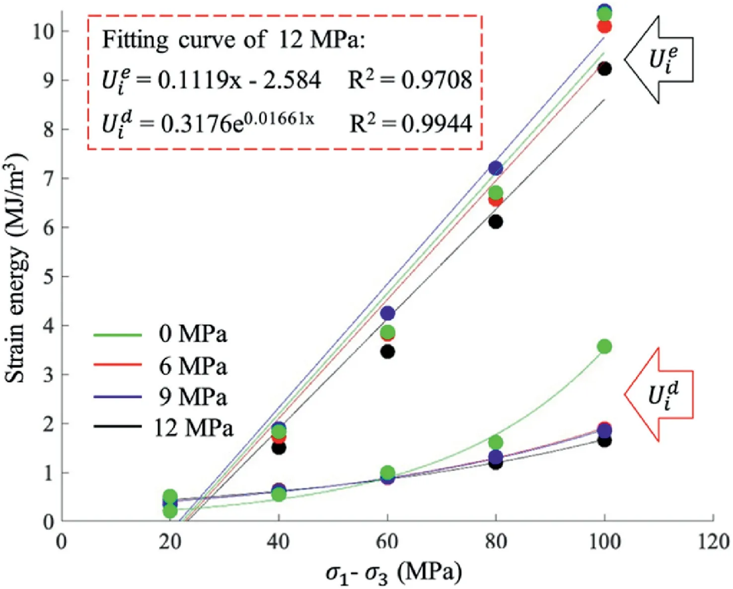
Fig.4.Strain energy and the deviatoric stress of RB-20-5 under different confinements.
4.3.Damage characterization by AE
4.3.1.AE energy evolution under uniaxial and triaxial conditions
The study compared the cyclic AE energy evolution of two RB specimens,RB-20-5-0 and RB-20-5-12,under uniaxial and triaxial conditions,respectively in Fig.5.Fig.5a shows that the AE energy of the RB-20-5-0 specimen increases during the loading phase and decreases during the unloading phase,which is the same as the result shown in Fig.5b for the RB-20-5-12 specimen.However,there are several differences between the two specimens: (1) The RB-20-5-0 specimen lacks the quiet period between cycles,(2)There is high AE energy release before and after the peak cyclic stress,(3) The peak strength (99 MPa) in the final cycle is lower than the deviatoric stress (100 MPa) in the fifth cycle,and (4) The AE energy increases significantly in the final cycle with a large amount of high AE energy signals.These differences indicate that the specimen has entered the yielding stage,and the internal damage has transformed from elastic to plastic,rapidly expanding the damage range and increasing crack connection,leading to visible damage.

Fig.5.AE energy and deviatoric stress changing with time for RB-20-5 under the uniaxial and triaxial conditions.
Fig.5b depicts the AE energy and the deviatoric stress as a function of time during the triaxial cyclic loading of the RB-20-5-12 specimen.During the first cycle,the duration is concise with multiple rapid AE signals that exhibit strong energy,which result from the compression and closure of original defects such as micropores and cracks.Upon entering the first unloading stage,the AE energy drops significantly.The high and low AE energies in these two stages are distinct.
In the second cycle,the intensity and value of the AE energy decrease even further compared to the first cycle,and a short period of low AE energy appears between the two cycles.A sudden surge of high AE energy occurs primarily when the deviatoric stress exceeds the previous loading stress(about 20 MPa),suggesting that new fractures are generated,and the primary fractures expand with a significant Kaiser effect.As the loading continues,the AE energy decreases slowly and eventually fluctuates within a small range before decreasing further after entering the second unloading stage.
During the next 3-5 cycles,the pattern of AE energy conforms to the initial quiet period followed by a sudden increase and slight decrease.However,the AE energy of each cycle is higher than that of the previous cycle,indicating that the RB-20-5-12 specimen is undergoing a stress adjustment stage,leading to only slight damage and the extension of microcracks due to repeated stress loading.
Finally,in the last cycle,an intensive high AE energy signal appears after surpassing the highest stress of the previous cycle,indicating that the pressure has reached the crack damage stress value,causing the microcracks to connect and form macroscopic cracks.
The Felicity effect indicates that if the maximum stress is closer to the stress corresponding to the maximum AE energy event in each cycle,the stress memory is delayed,otherwise,the stress memory is advanced (Zhang et al.,2017;Li et al.,2019).Based on the results,the RB specimen exhibits a poor stress memory in uniaxial conditions and an excellent stress memory in triaxial conditions.The "quiet period" also reveals that the RB specimen under triaxial conditions is more elastic than the uniaxial specimen,and higher loads are needed during reloading to reopen the microcracks that were compacted during the previous unloading stage (Li et al.,2016).In conclusion,the cyclic AE phenomenon reflects the different Kaiser effects of the RB specimen under uniaxial and triaxial conditions.
4.3.2.Damage mode transformation
The results of the cyclic loading process on the RB specimens under different confining pressures are reflected in the hysteresis loop,dissipated energy,and AE activities.Higher confinement results in elastic and stress memory properties in the specimens.This can be observed in the distribution of the RA and AF density of the RB-20-5 specimens after five cycles.The color-coded signals in Fig.6,from blue to red,represent the density of the signals from low to high.

Fig.6.Density distribution of AF and RA for RB-20-5 under 0,6,9,12 MPa confinement.
With increasing confining pressure,the microcracks become more abundant and widely spread.Both the maximum values of RA and AF increase,but the number of signals with higher RA increases significantly.The high-density region shifts significantly in the positive direction of theX-axis,indicating that with an increase in lateral stress,the inclination angle of the maximum principal stress decreases,the likelihood of shear damage increases,and the number of shear microcracks also increases.
The density distribution of RA and AF signals during the cyclic loading process of RB-20-5-12 specimen is shown in Fig.7.It can be seen that the maximum AF of the AE signals is generally higher in the loading stage compared to the unloading stage.For instance,in the third cycle,the maximum AF in the loading stage is 135 kHz,while in the unloading stage it is only 40 kHz.Similarly,in the fifth cycle,the maximum AF in the loading stage is 145 kHz,whereas in the unloading stage,it is only 48 kHz.On the other hand,the maximum RA of the AE signals is generally lower in the first two cycles but increases with repeated loading.Based on the microcrack classification method we illustrated in Section 3.2,this indicates that the loading process generates more tensile microcracks,while repeated cyclic loading leads to the formation of more shear microcracks.
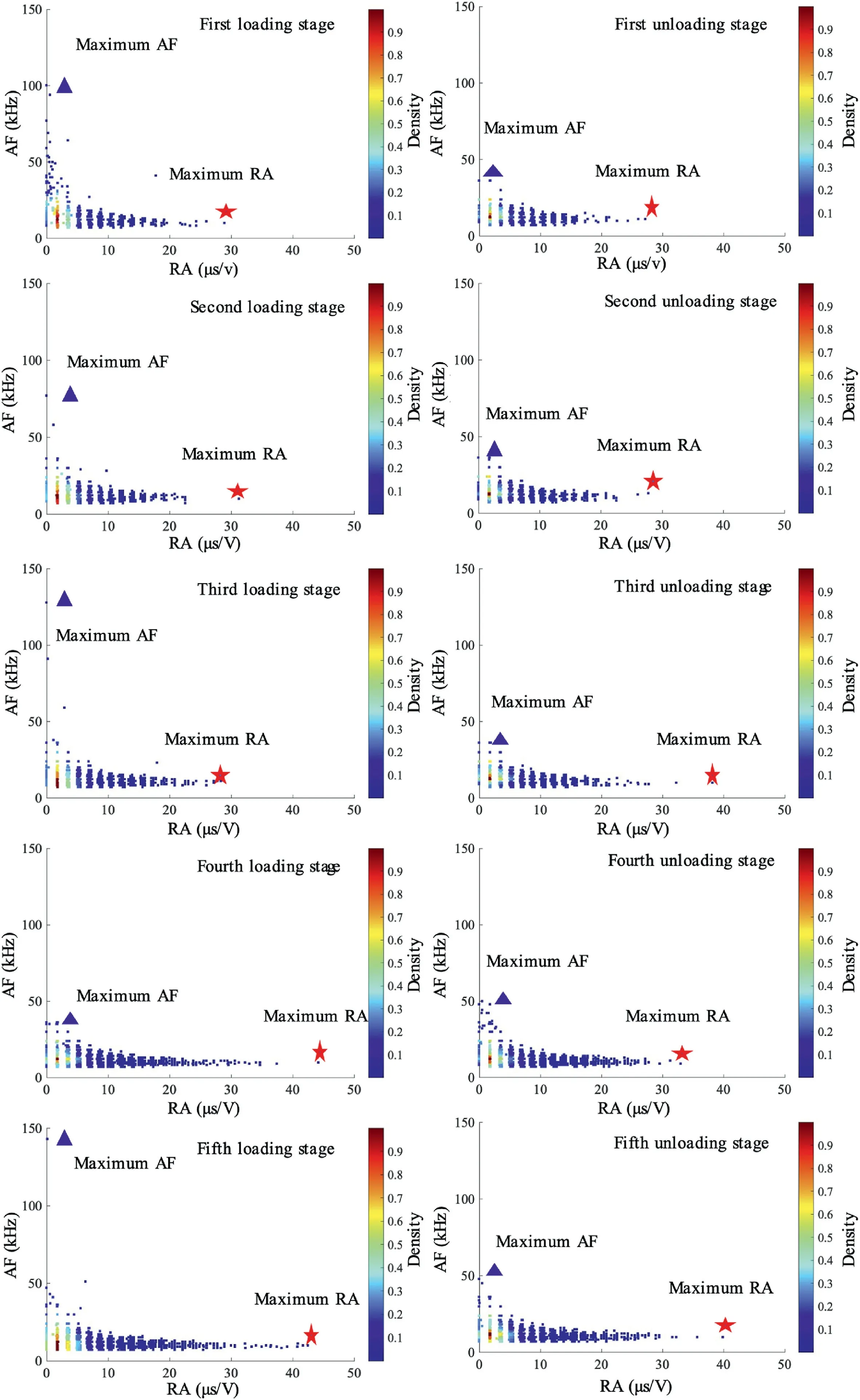
Fig.7.Density distribution of AF and RA for RB-20-5-12 within each cyclic loading and unloading stage.
Fig.8 shows the distribution density of AF and RA within each cycle of the RB-20-5-12 specimen.The results suggest that the maximum RA gradually increases with each repeated cycle.In the first cycle,the maximum RA is about 30 μs/V,but the maximum RA is about 44 μs/V in the fourth cycle.This increase indicates that the appearance of shear microcracks is more likely with cyclic time.Most of the signals within each cycle are distributed near the origin,which suggests that the cyclic process has little effect on the density distribution of the signal parameters.This also means that the crack is always in a stable development state during the cyclic process,with many low-energy microscopic cracks dominating the damage.

Fig.8.Density distribution of AF and RA for RB-20-5-12 within each cycle.
In conclusion,the results of this study indicate that the RB specimens exhibit different elastic and damage behaviors under different confining pressures,which are closely related to the distribution and evolution of AE signals.With increasing confining pressure,the microcracks increase and spread,the number of shear microcracks increases,and the maximum RA of the AE signals gradually increases.Moreover,with increased cyclic stress,the shear microcracks increased,eventually leading to inelastic and irreversible mesoscopic damage near failure.
4.4.3D fracturing skeletonization
The results of the 3D fracture skeletonization analysis of three specimens(RB-30-3-6,RB-30-3-9,and RB-30-3-12)using 3D image data were presented.The 3D fracture aperture is presented using color,with blue indicating low aperture and red indicating high aperture.The distribution of the fracture aperture in the rock and backfill during the test is used to analyze the cyclic damage evolution compared to the traditional monotonic fracture morphology.With triaxial loading,cracks in the 3D fracturing skeletonization can be classified easily by visually examining the 2D and 3D original figures.Shear cracks exhibit opposite movement on either side and a small dipping angle of the cracking plane,while tensile cracks show little opposite movement and are mostly vertical.
In summary,Fig.9 presents the 3D post-failure fracture of the RB-30-3-6 specimen,Fig.9a shows the main view and Fig.9b shows the oblique view.The comprehensive fracture is concentrated on the rock and the interface between the rock and backfill at the bottom of the specimen.The fractures consist of severe circular shear cracks along the hollow rock and some axial splitting tensile cracks.The distribution of fracture openings in the rock is characterized by two types of fractures: very large (red) and very small(dark blue) fractures that are not spatially concentrated.The interface crack openings are mainly of medium size,dominated by green color,and have a more concentrated distribution,showing clear evolution of cracks.

Fig.9.Post-failure fracture skeletonization of RB-30-3-6: (a) Main view,and (b) Oblique view.
Fig.10 presents the fracture skeletonization of RB-30-3-9,which was established from the 3D image data.It should be noted that in the 3D original damage reconstructed model scanned before failure,this specimen has patches of strip-like pores and fissure groups at the top of the inner backfill,and no apparent clustering fissures exist in other specimens.The main view of the overall fracture is shown in Fig.10a,while Fig.10b shows the top view,and Fig.10c shows the separated fracture in the outside rock.Unlike past studies where rock starts to rupture first,both in uniaxial and triaxial compression conditions,this specimen is different(Yu et al.,2021a,b,c,d).Cracks were produced in the rock,the backfill,and their interface,and the intense patches of cracks were mainly distributed along the interface.Most fractures in the interface have high and medium aperture with continuous evolution paths.There are several discontinuous areas presented by blue radiating rays,indicating that the cracks in this area are discontinuous and very sporadic.Based on the current algorithm,it is not possible to be sure that it is a null area,thus the cracks are forcibly connected.Some crack also propagated into the backfill from the interface and expanded the original fissure (Fig.10b).The cracks in the rock are discrete,unrelated,and small,and are mainly obtained from the extension of interface cracks.

Fig.10.Post-failure fracture skeletonization of RB-30-3-9: (a) Main view,(b) Top view,and (c) Separated rock fracture in main view.
In Fig.11,the post-failure fracture skeletonization of the RB-30-3-12 is shown.Fig.11a shows the main view,while Fig.11b shows the top view.The fracture is seen to be concentrated on the top of the specimen and is more isotropic and dispersed compared to the other specimens.The main crack is a circular shear crack,similar to that seen in the RB-30-3-6 (Fig.9).In addition to the main crack,scattered discontinuous cracks are seen to be distributed on the other side of the main crack.

Fig.11.Post-failure fracture skeletonization of RB-30-3-12: (a) Main view,and (b) Top view.
Under monotonic triaxial compression,the fracture is dominated by shear cracks that exhibit a wide distribution and large aperture.However,under triaxial cyclic loading and unloading conditions,the crack distribution becomes more discrete with smaller openings and no predominant crack types.This suggests that the location of stress concentrations changes with the number of cycles.The application of stepwise-increasing cyclic stress restricts the extent of microscopic crack initiation and expansion,leading to the accumulation of a substantial number of mediumscale damage cracks during the elastic stage of the specimen.Upon reaching the yield stress,the accumulated medium-scale damages trigger a large-scale overall failure,causing the specimen to break more extensively.To fully comprehend the final spatial failure mode of the RB structure,it is crucial to determine the degree of discrete damage that occurs in the discontinuity under cyclic loading and unloading conditions.The analysis and summarization of crack spatial and temporal evolution can be facilitated by combining the monitoring results of dynamic AE,including the examination of special RB-30-3-9 specimens with backfill cracks.
5.Discussion
5.1.Shear cracking behavior
Our prior research (Yu et al.,2021a,b,c,d) discovered a distinct difference in the type and energy of AE failure signals in RB specimens compared to intact rock (R) specimens under 9 MPa confinement.In the R specimens,numerous tensile microcracks appeared,resulting in a macroscopic fracture that manifested as a coalescence of tensile and shear fractures.This was because tensile microcracks were generated first during the compression and elastic stages,followed by the appearance of shear cracks in the yield stage,which connected the established extensive tensile damage,forming a cluster of tensile-shear macrocracks.This significant failure pattern of granite was observed in both RB and R specimens,consistent with the damage evolution pattern of granite reported by Feng et al.(2021)(as shown in Fig.12a),indicating that the internal damage mechanism of granite is still evident in the compression process of RB specimens.

Fig.12.(a) Damage evolution pattern of granite,and (b) AF and RA changing with the time of RB-20-5-12 specimen.
However,in RB specimens,in addition to the tensile microcracks that appeared in the elastic stage,an equally significant number of high-energy shear microcracks also emerged.This indicates that the damage mode of the granite inside the RB is not homogeneous.
In Fig.12b,the 3D plots of the AE signal’s RA and AF are presented for the RB-20-5-12 specimen.The data show that,except for the first cycle,there is a sudden increase in the RA of the signals and a low AF at the initial stage of each cycle (approximately 500 s,1000 s,and 1500 s),which corresponds to the generation of a large number of shear microcracks.As the loading continues,the number of shear microcracks decreases.This observation suggests that when the number of tensile microcracks that developed during the previous cycle is sufficient and the spacing of microcracks is small enough,new shear microcracks quickly emerge upon reloading.However,when the loading rate is constant and uniform,the probability of shear microcrack generation is lower.
The data processing procedure of the RB-20-5-12 specimen is shown in Fig.13a.Using the acoustic signal classification method(as described in Section 3.2),the tensile and shear microcracks are represented by blue and orange dots in Fig.13a,respectively.During the first cycle,high-energy tensile microcracks are observed,while subsequent crack formation releases relatively low AE energy.In the following cycles,the density of high-energy shear microcracks increases,showing a pattern of sparse-to-dense transition and indicating a gradual increase in shear damage.The AE energy distribution of the two types of microcracks shows that the energy caused by tensile microcracks is widely distributed (ranging from 0 to 10,000).In contrast,the AE energy caused by shear microcracks is more concentrated(between 30 and 1000).The AE energy can be used to represent the extent and scale of cracks to some degree.It suggests that the distribution of tensile microcracks is uniform from small to large,while medium and large-sized cracks are dominant in shear microcracks.
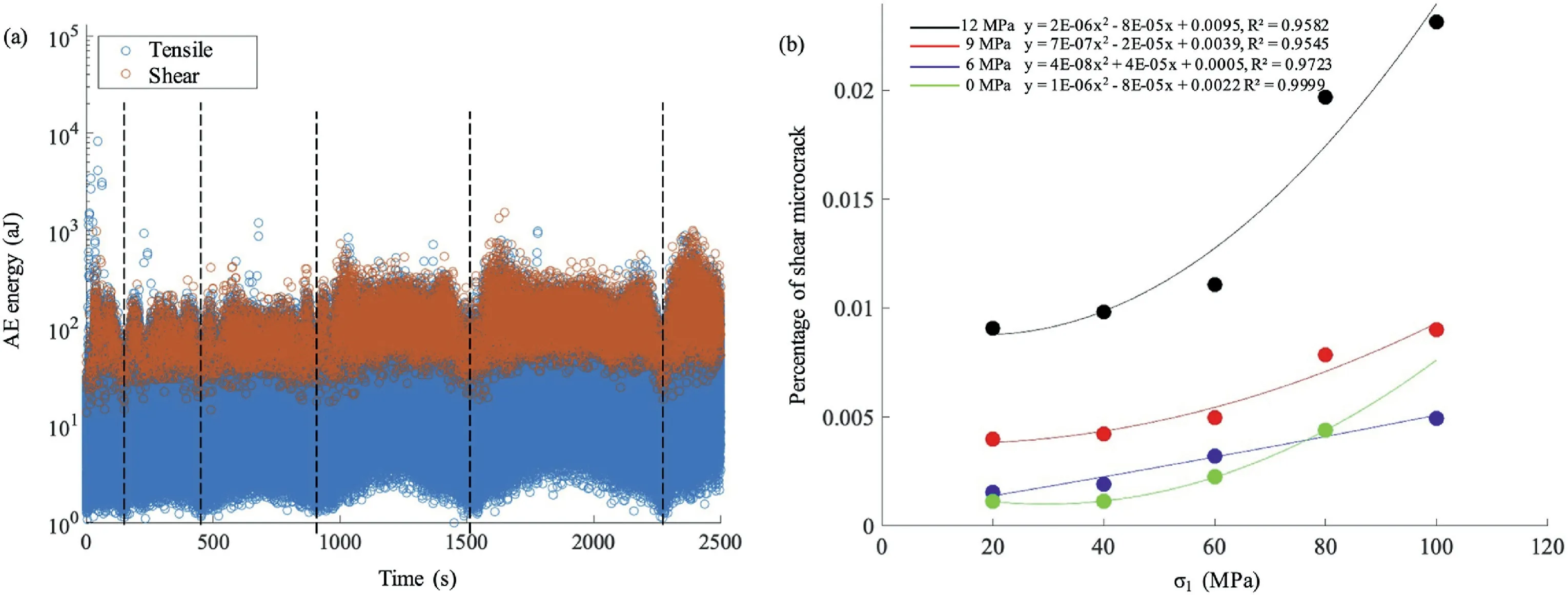
Fig.13.(a) AE energy of shear and tensile microcracks of RB-20-5-12;and (b) Percentage of shear microcrack of RB-20-5 specimen under 0,6,9 and 12 MPa confinement.
To quantitatively characterize the evolution of shear microcracks during the cyclic process,the percentage of shear microcracks in the total number of AE signals in each cycle of RB-20-5 under each confining pressure was calculated by MATLAB(Fig.13b and Table 4).Results show that the percentage of shear microcracks is significantly smaller than that of tensile microcracks,with a maximum of only 2.31%.The percentage of shear microcracks increased with the increase of cyclic stress,following a pattern of“slow growth-rapid growth-slow growth again”.This pattern is explained by the fact that at the early stage of loading(compacting stage),the primary signal is transverse wave.As axial stressincreases from 60 MPa to 80 MPa,tensile microcracks propagate to a certain extent,and shear microcracks appear in large numbers to connect the original crack.A large amount of mesoscale damage appears inside the RB specimen.This results in a substantial increase in the percentage of shear microcracks,indicating a stable stage of cracking development.After the connection between the shear microcracks is complete,both types of cracks complete the crack expansion,and there is little shear failure before entering the yielding stage.Observation on the fitted curves of the percentage of shear microcracks and deviatoric stress in Fig.13b showed that the percentage of shear microcracks increased significantly with the increase of confining pressure.All percentages of shear microcracks increased significantly when the deviatoric stress exceeded 60 MPa,with the growth rate being the fastest when the confining pressure was 12 MPa.The dissipation energy showed a similar regular change pattern (Fig.4),indicating a direct link between shear microcracking and irreversible damage.The increase of confining pressure and deviatoric stress beyond 60 MPa resulted in a change in the microscopic crack expansion pattern,leading to intense mesoscale damage dominated by shear microcracking.

Table 4Percentage of shear microcrack of RB-20-5 specimen under 0,6,9,and 12 MPa confinement.
The study found a relationship between the VF,cyclic loading rate,confining pressure,and percentage of shear microcracks in a rock specimen.Fig.14 shows the plotmatrix of all variables to show their relationships.The shear microcracks percentage was found to increase and then decrease as the VF and cyclic loading rate increased in Fig.14a and b.With the increase of cyclic stress,the overall percentage of shear microcracks showed slow growth followed by accelerated growth(Fig.14d).The confining pressure also had an impact,with the overall percentage of shear microcracks gradually increasing with its growth (Fig.14c).The highest percentage of shear microcracks (0.04) was found in the RB-30-4 specimen with a VF of 0.61 and a cyclic loading rate of 400 N/s.The percentage of shear microcracks was also found to be greater at a confining pressure of 9 MPa compared to 12 MPa.The growth of the shear microcracks rapidly increased when the cyclic stress was raised from 20 MPa to 40 MPa and then slowed down.

Fig.14.Relationship of VF,cyclic loading rate,confining pressure,cyclic stress,and percentage of shear crack.

Fig.15.3D cracks and AE microcrack signals of RB-30-3 under different confinements.
5.2.Damage localization between rock and backfill
To gain insight into the reasons behind the observed variations in shear damage behavior among specimens and the impact of the interaction between rock and backfill on damage progression,we conducted a comparative analysis of the 3D fracture morphology and AE energy evolution of the RB-30-3 specimen under confinement of 6,9,and 12 MPa after failure,as shown in Fig.15.
The results showed that,under a confinement of 6 MPa,the predominant form of conjugate shear fractures was observed in the outer rock.However,at 9 MPa,the presence of scattered fractures in the outer rock was accompanied by the emergence of a widespread range of circular fractures at the rock-backfill interface.Finally,at 12 MPa,the phenomenon of conjugate fractures was diminished,and instead,a pure shear fracture was observed at the upper end of the rock.
In terms of AE microcrack signals,the RB-30-3 under 9 MPa confinement displays a distinct behavior.Its peak strength is lower than that of the specimens subjected to different levels of confinement.During the cyclic loading process,the number of shear microcracks significantly decreases (represented by a decrease in red scattering),and a sudden emergence of high-energy tensile microcracks occurs near the previous failure cycle and the failure point,resulting in a drop of residual stress to zero.On the other hand,for the specimens under 6 MPa and 12 MPa confinement,a substantial number of shear microcracks are produced during the cyclic loading process,and the residual stress remains at around 35%of the peak stress.
This finding highlights the fact that backfill can enhance the shear capacity of rock by providing support and friction force and thus enabling stress transfer.However,if the initial damage within the backfill is excessive,its strength decreases and its adhesion to the rock weakens(as seen in the case of the RB-30-3-9 specimen).Under compression,although the backfill bears more stress transferred from the rock and reduces the degree of rock fragmentation,its weakened adhesion makes it more susceptible to failure,leading to the early destabilization of the rock-backfill interface.As a result,the RB structure experienced catastrophic failure without any residual capacity.
In conclusion,a specific combination of the VF and cyclic loading rate can result in an accelerated growth of shear failure,an earlier strain hardening stage,and a shorter elastic stage in rock-backfill structures.Given the presence of original clustering pores in the backfill,it is important to pay close attention to cracking potential along the rock-backfill interface rather than solely within the rock.Future research should focus on enhancing the cohesion and stiffness of the rock-backfill interface to eliminate dominant tensile damage prior to rock failure.The transformation of damage from shear to tension will result in distinct 3D fracture distributions and evolution patterns between rock and backfill,leading to the final failure mode of the structure.The dissipation energy and AE signals during the cyclic loading process provide valuable insight into this phenomenon,showing a relationship with the cyclic stress and a strong positive correlation with each other.However,further investigation is required to discriminate the correlation and correction between these two methods.This will improve our understanding of mechanisms for preventing excessive strain softening(brittle)failure in rock masses and reducing the likelihood of induced seismicity in deep mining operations.
5.3.Failure mechanism between rock and backfill
The interplay between the rock and backfill in bi-material structures under triaxial stress conditions has a marked impact on their failure mechanisms.A comparison and analysis of the cyclic effect between the rock and backfill is necessary,thus the influence of confinement and VF on the failure mode of the RB structure under monotonic triaxial compression was concluded based on previous studies(Li et al.,2019;Weilv et al.,2021;Yu et al.,2022) as depicted in Fig.16a.As confinement increases,end-only shear damage is observed to predominate,while an increase in VF leads to a predominance of intermediate multiple shear damage.

Fig.16.Monotonic triaxial (a) failure mode,(b) stress state before and (c) after peak in the RB structure.
According to the difference of the main failure modes,the stress state of the upper end of the BR specimen is characterized by two main stages,as depicted in Fig.16b and c:
(1) The initial rock-bearing stage: This stage encompasses the initial compression stage,elastic stage,yielding stage,and peak failure.During this stage,the stress is mainly concentrated in the hollow,thin-walled rock column,with relatively small end shear stress and supporting forces contributed by the backfill.As the VF increases and the confining pressure decreases,the shear stress is reduced and the interface failure is minimized.Conversely,as the VF decreases and the confining pressure increases,the damage is concentrated at the bottom,leading to an increase in shear stress,fracture energy,and contact support force.
(2) The secondary rock-bearing stage: This stage includes the stepping failure stage after peak and the residual deformation stage.The confining pressure plays a crucial role in determining the post-peak mechanical properties during this stage.If the confining pressure is high and the VF is low,the broken rock expands and slips,and the backfill provides increased support and friction force to counteract the sidewise pressure.However,as the axial stress continues to increase,the contact surface is gradually destroyed under the influence of friction and tension,leading to secondary shear damage that expands along with the main shear damage that occurred in the first stage.Conversely,if the confining pressure is low and the VF is high,the tendency of the rock to slip is weaker,and the support of the backfill is sufficient to resist the sidewise pressure while also providing internal resistance to the hollow,thin-walled broken rock.The result is a partial cancellation of the internal and external lateral pressures,leading to significant internal tension in the broken rock and triggering severe tensile damage(Yang et al.,2020b).
In conclusion,the results indicate that under monotonic triaxial compression,the RB specimens exhibit minimal macroscopic damage prior to peak failure.
The analysis of AE microcrack signals and 3D fractures in cyclic triaxial tests has indicated that the RB structure undergoes crack formation with unique spatial and temporal characteristics,even before any macroscopic cracks appear.Unlike in the case of monotonic triaxial compression,the nucleation and growth of cracks in the cyclic process are more complex.As the crack progresses from microscopic to macroscopic,it commonly follows a process of initiation,extrusion,extension,and subsequent repeated extrusions and extensions(as shown in Fig.17a)(Boeff et al.,2019).During each loading stage,the stress field in the RB structure is redistributed,and the stress localization caused by pre-existing cracks is different from that of the previous cycle.New cracks may emerge around the existing cracks or in other locations,eventually forming interconnected and irreversible damage when the material loses elasticity.This process is also influenced by the intrinsic nature of the material(Geranmayeh Vaneghi et al.,2020).In our study,the rock samples used were relatively homogeneous granite,and thus,the cyclic damage was fragmented.However,inhomogeneous rocks may exhibit more concentrated cyclic damage.Furthermore,when the homogeneity of the backfill is poor,a similar pattern of cyclic damage may not be observed only in the rock material.If the backfill is homogeneous with an initial,uniform distribution of pore fractures,its support force on the rock dominates,and both the backfill and rock are able to undergo simultaneous elastic deformation in the axial direction,leading to minimal frictional force between the two materials.However,in the case of non-homogeneous backfill,the presence of internal initial pore fractures reduces the backfill’s support force on the rock,and the internal fractures are repeatedly squeezed and expanded during the cyclic loading process,leading to a mismatch in deformation rates between the rock and backfill materials.This results in irregular and variable frictional forces between the two materials,causing repeated friction between the rock-backfill interface and potentially leading to the destruction of their contacting adhesion (the conceptual model is shown in Fig.17b).
5.4.Implication for engineering
The RB structure in underground mining stopes is characterized by the transfer of lateral pressure from the rock to the backfill,which can be destabilized by externally imposed unstable axial pressure.Studies have concluded that there are three major ways that backfill interacts with rock: (1) stress absorptiontransformation,(2) contacting support,and (3) stress isolation(Hassani et al.,2001).The stress absorption-transformation mechanism refers to the ability of the rock stress to be absorbed and transformed by the backfill.On the other hand,stress isolation refers to the isolation and redistribution of localized rock stress under the influence of the backfill.Based on the three popular mechanisms and the intertwined mechanics of rock and backfill under monotonic and cyclic triaxial loadings described in the previous section,it is important to not only consider the contacting support effect on the bi-material interface,but also the contact friction effect.The axial and lateral contact frictions play a crucial role in the failure mode of RB structure.The interaction response characteristics of backfill to rock mass are dependent on rock pillar width and stope depth(Fig.17b).Therefore,the ratio and strength of the backfill can be adjusted based on different stope conditions,leading to the development of more effective backfilling strategies.
In cases where the rock is brittle with high strength and loaded with large horizontal in situ stress,adding other materials to the backfill slurry or reducing its particle size can increase the contacting stiffness between the rock and backfill (Koupouli et al.,2016;Weilv et al.,2021;Fang et al.,2022a,b;Singalreddy et al.,2022),thereby improving its softness and resistance to long-term high stress perturbations and large damage (Wang and Li,2022).However,the role of the backfill is mainly reflected after the rock has undergone initial damage.An increasing initial damage of the backfill may lead to a decrease in contacting support and an increase in contacting axial friction,which in turn may result in severe damage at the interface between the two materials.
In addition,Fang et al.(2022a,b)found that the stress reduction of backfill will not continue to decrease as the stope width grows in the field scale numerical modelling,which means the contact supporting force of the backfill to the rock will not always increase.This validated and explained our finding why the proportion of shear microcracks in the RB structure rises,and then declines as the VF and cyclic loading rate increase.That is because if the contacting supporting force is constant,the interface’s cohesion decreases as the strength of backfill and contacting axial friction increase,resulting more extensive interface friction and openings.Once the interface opened,the crack would prefer to propagate through the axial weak interface plane(Koupouli et al.,2016;Li et al.,2022),and extensive tension microcracks are generated.These specific transitional intervals that control the damage mode evolution law between the rock and backfill need to be further investigated.
The characterization of acoustic signals,dissipation energy,and 3D cracks in this study presents a valuable method for defining damage variables in geomaterials,a crucial aspect in the development of a strength investigation constitutive model.There are numerous proposed ways to evaluate the damage variable,including internal crack volume and dissipated energy,which have been incorporated into various statistical damage theories,such as the Weibull distribution function(Chen et al.,2018).However,most constitutive models can only be verified and applied using specific parameters on unique instrumentation,which is hard to obtain by the general research community.Our AE results established a positive correlation between shear microcracks and dissipated energy,which provides insight into the relationship between AE signals,dissipated energy,and microscale visual crack.The classification of AE signals in relation to cracks is well established and has a direct correlation with the morphology of cracks.This relationship enables the inference of the pattern of microscopic cracks through 3D crack visualization.An examination of the correlation between the acoustic shearing signals,dissipated energy,and microscale visual damage is necessary.The integration of staged CT scans in future studies holds the potential to establish a connection between these three experimental parameters,thus reducing experimental expenses and encouraging a greater number of scholars to engage in constitutive modeling studies,ultimately leading to the establishment of mathematical models among various constitutive variables.
6.Conclusions
In this study,tests were conducted on rock-encased backfill specimens (RB) subjected to stepwise cyclic triaxial loading,with variables that included confining pressure,rock to backfill volume fraction (VF),and cyclic loading-unloading rates.Cyclic loading resulted in a complex damage evolution due to microcrack growth and coalescence in the rock,backfill and rock-backfill contact.This damage evolution and meso-crack formation was analyzed through the stress-strain hysteresis loops,AE events,and post-failure X-ray 3D fracture morphology.
This study represents a unique set of experiments considering both bi-materials (rock and backfill) and cyclic loading,with important implications for underground geoengineering.The construction of stable underground excavations in mining and underground civil works will involve both multi-materials of varying strengths(soil,rock,backfill and concrete for example)and dynamic events due to blasting,excavation sequence,and natural seismic events.This study has provided some important results and conclusions that can help to understand and maintain stable underground environments.Four key conclusions from this study are given below:
(1) Our results show that the stress-strain hysteresis loops under cyclic loading provide important practical information related to rock mass strain hardening,stress memory(Kaiser effect),elastic and dissipated energy,and ultimate strength.One important finding is that as a function of the number of cycles,the elastic strain increases linearly and the dissipated energy increases exponentially.A second important result is that compared with monotonic loading,the cyclic strain hardening characteristics are more sensitive to rising confining pressures during the initial compaction stage.Both of these observed phenomena will have an impact on the ability of backfill to stabilize underground excavations.
(2) The AE and X-ray imaging results have provided key information on the evolution of tensile and shear microcrack growth and the formation of meso-fractures.One finding is the importance of shear microcracks in the emergence of both strain hardening and stress memory in the cyclic tests.Another finding is the additional shear microcracks that are generated during every reloading stage,which tend to be dispersed and lessen the likelihood of large shear fracture formation compared with monotonic loading.Thus,even though cyclic loading results in lower ultimate strengths compared with monotonic loading,cyclic loading results in some key differences that could in some instances positively impact the ability of backfill to support rock.
(3) The variables that were considered in our testing (confinement,VF,cyclic rate) reflect engineering design factors in actual underground construction (blasting frequency,backfill to rock ratio,mining depth).Our results show important trends as these parameters are varied,particularly in terms of the transition from elastic to plastic deformation.The transformation to plastic behavior is significantly lower under the conditions of 0.73 rock volume fraction,400 N/s cyclic loading rate,and 9 MPa confinement.This is due to the results that show that dissipated energy increases with increased shear microcrack events,and the generation of shear microcracks increases quadratically with the number of loading cycles,but increases and then decreases with increasing rock volume fracture,cyclic rate,and confining pressure.
(4) A conceptual model was developed for how damage and failure occur in the RB samples under cyclic loading.One important aspect of the conceptual model is the importance of the contact forces and associated friction along the rockbackfill contact,which when low can result in significant contact separation and damage,and which is of practical importance in underground geoengineering with backfill.
The work presented here is unique and builds upon many studies of single material samples under monotonic and cyclic loadings,and bi-material samples under monotonic loading.As far as we know,this is the first comprehensive set of tests on rock encased backfill samples under cyclic loading.In the future,additional research is needed to fully characterize the relationships between AE signals,dissipated energy,and 3D fracture morphology,and in particular to develop constitutive models for the damage and failure of bi-material structures under cyclic loading.These constitutive relationships can then be input into 3D numerical models to accurately simulate the actual material response of underground excavations with backfill under cyclic loading due to excavation sequence,blasting,and natural seismic events such as earthquakes.Future research also needs to consider the effects of water and pore pressure in these conditions.
Declaration of competing interest
The authors declare that they have no known competing financial interests or personal relationships that could have appeared to influence the work reported in this paper.
Acknowledgments
We acknowledge the funding support from the National Natural Science Foundation of China Youth Fund(Grant No.52004019),the National Natural Science Foundation of China(Grant No.41825018),and China Postdoctoral Science Foundation (Grant No.2023M733481).The suggestions on paper writing given by Khan Zada from the University of Chinese Academy of Sciences are greatly appreciated.
杂志排行

Journal of Rock Mechanics and Geotechnical Engineering的其它文章
- Determination of uncertainties of geomechanical parameters of metamorphic rocks using petrographic analyses
- Evaluation of excavation damaged zones (EDZs) in Horonobe Underground Research Laboratory (URL)
- On the calibration of a shear stress criterion for rock joints to represent the full stress-strain profile
- Effect of dynamic loading orientation on fracture properties of surrounding rocks in twin tunnels
- Experimental study on the influences of cutter geometry and material on scraper wear during shield TBM tunnelling in abrasive sandy ground
- Effect of fracture fluid flowback on shale microfractures using CT scanning