Experimental study on the influences of cutter geometry and material on scraper wear during shield TBM tunnelling in abrasive sandy ground
2024-02-29ShaohuiTangXiaopingZhangQuanshengLiuQiZhangXinfangLiHaojieWang
Shaohui Tang ,Xiaoping Zhang,* ,Quansheng Liu ,Qi Zhang ,Xinfang Li ,Haojie Wang
a Key Laboratory of Safety for Geotechnical and Structural Engineering of Hubei Province,School of Civil Engineering,Wuhan University,Wuhan,430072,China
b State Key Laboratory of Water Resources and Hydropower Engineering Science,Wuhan University,Wuhan,430072,China
Keywords:Shield TBM Scraper wear Cutter shape Metal material Alloy hardness
ABSTRACT When shield TBM tunnelling in abrasive sandy ground,the rational design of cutter parameters is critical to reduce tool wear and improve tunnelling efficiency.However,the influence mechanism of cutter parameters on scraper wear remains unclear due to the lack of a reliable test method.Geometry and material optimisation are often based on subjective experience,which is unfavourable for improving scraper geological adaptability.In the present study,the newly developed WHU-SAT soil abrasion test was used to evaluate the variation in scraper wear with cutter geometry,material and hardness.The influence mechanism of cutter parameters on scraper wear has been revealed according to the scratch characteristics of the scraper surface.Cutter geometry and material parameters have been optimised to reduce scraper wear.The results indicate that the variation in scraper wear with cutter geometry is related to the cutting resistance,frictional resistance and stress distribution.An appropriate increase in the front angle(or back angle)reduces the cutting resistance(or frictional resistance),while an excessive increase in the front angle (or back angle) reduces the edge angle and causes stress concentration.The optimal front angle,back angle and edge angle for quartz sand samples are α=25°,β=10° and γ=55°,respectively.The wear resistance of the modelled scrapers made of different metal materials is related to the chemical elements and microstructure.The wear resistances of the modelled scrapers made of 45#,06Cr19Ni10,42CrMo4 and 40CrNiMoA are 0.569,0.661,0.691 and 0.728 times those made of WC-Co,respectively.When the alloy hardness is less than 47 HRC (or greater than 58 HRC),scraper wear decreases slowly with increasing alloy hardness as the scratch depth of the particle asperity on the metal surface stabilizes at a high (or low) level.However,when the alloy hardness is between 47 HRC and 58 HRC,scraper wear decreases rapidly with increasing alloy hardness as the scratch depth transitions from high to low levels.The sensitive hardness interval and recommended hardness interval for quartz sand are [47,58] and [58,62],respectively.The present study provides a reference for optimising scraper parameters and improving cutterhead adaptability in abrasive sandy ground tunnelling.
1.Introduction
Although the shield-driven method has been widely used in tunnel construction (Martinelli et al.,2015;Wei et al.,2020;Liu et al.,2022;Lin et al.,2022;Shen et al.,2023;Sun et al.,2023;Tan et al.,2023;Xu et al.,2023;Zhang et al.,2023),there are still uncertainties and challenges when tunnelling in complex geological conditions (Barla,2016;Gong et al.,2016;Hasanpour et al.,2017;Acun et al.,2021;Zhang et al.,2021a,b;Tang et al.,2021a,b,2022,2023).Taking abrasive ground as an example,the geological adaptability of cutting tools has not been completely resolved due to the complex interaction between the soil and cutter(Li et al.,2017;Fu et al.,2021;Tang et al.,2020;Xia et al.,2021;Zhang et al.,2021a).Frequent downtime for tool maintenance has become a critical factor restricting tunnelling efficiency and construction safety (Alavi Gharahbagh et al.,2013a;Barzegari et al.,2015;Amoun et al.,2017;Conrads et al.,2018;Yang et al.,2021).Especially for long-distance tunnelling in sandy ground,irregular particles with high quartz content squeeze and rub cutting tools(Mirmehrabi et al.,2016;Tang et al.,2020;Zhang et al.,2021a).Primary wear is reflected as microcutting and surface scratching increases during the extrusion and friction processes (Küpferle et al.,2018;Wei et al.,2019;Farrokh,2021).Moreover,ground disturbance induced by shield tunnelling leads to sand liquefaction,which reduces soil strength and collapses the tunnel face(Farhangi et al.,2020).A large amount of residual sand is prone to accumulate on the cutterhead edge (Köppl et al.,2015;Tabrizi et al.,2023).Secondary wear presented as repeated grinding and surface polishing increases as residue sand rotates with the cutterhead(Jakobsen et al.,2013;Barzegari et al.,2015;Farrokh,2021).How to design cutting tools with better geological adaptability to reduce abrasive wear has become a critical challenge in sandy ground tunnelling (Küpferle et al.,2017;Tang et al.,2020;Zhang et al.,2021a;Li et al.,2022).
As one of the important components of soil-tool tribological systems,cutter geometry and material parameters such as geometry,material and hardness have a significant influence on scraper wear (Tang et al.,2020;Zhang et al.,2021a).In terms of cutter shape,Huang(2010)analysed the effect of scraper angles on cutting efficiency and found that scraper wear increases with increasing front edge.Since the tests were conducted under the condition of back angle β=10°and metal material 45#,it is debatable whether the results are suitable for scrapers with other back angles and metal materials.Guo and Dai (2013) studied the relationship between scraper wear and cutter shape and optimised cutting efficiency by reducing the front angle,increasing the edge angle and dulling the cutter edge.However,the tests were conducted under the condition that multiple parameters changed at the same time.The variation in the half angle and alloy size significantly interfered with the test results.Salazar et al.(2018) designed cutting tools with sharp cone angles,and qualified cutting tool wear by comparing the cutter edge before and after wear.However,the impeller-shaped modelled scraper cannot characterize the front angle,back angles and edge angle of the wedge-shaped shield scraper.Xia et al.(2019)evaluated scraper performance by specific energy consumption and load fluctuation coefficient,and analysed the variation in scraper wear with cutter shape.The cutter shape focuses on the cutter tooth arrangement rather than the cutter edge angle.Hence,it is necessary to design modelled scraper with cutter edge angles that agree well with those of the shield scraper to study the variation in scraper wear with the front angle,back angle and edge angle.
In terms of metal materials,Chen (2015) and Liu et al.(2020)studied the relationship between material composition and cutter performance and improved the wear resistance of cutting tools by increasing the content of Ni and V or adding the trace element Nb.The improved metal material is wear-resistant when manufactured into a milling tool in the machining industry.However,whether it can be utilized for cutting geomaterials in the tunnel industry is still debatable.Küpferle et al.(2017) revealed the correlation between the metallographic structure and microwear mechanism,and improved the tribomechanical properties of cutting tools by optimising the surface treatment processes.Since the surface treatment cannot change the internal structure of the metal material,the improvement of wear resistance is relatively limited.Wei et al.(2021) compared the wear resistance of cutting tools made of WC-Co and Q235 and found that the wear rate of cutting tools made of WC-Co was much lower than that of cutting tools made of Q235.However,there is still a lack of parameters that can quantify the relative wear resistance of cutting tools made of different metal materials in abrasive ground tunnelling using a shield TBM.
In terms of alloy hardness,Zum Gahr (1988) and Axén et al.(1994) explored the influence of alloy hardness on metal wear and revealed the wear law of the transition from low to high levels.However,this relation was obtained when the two friction pairs were metal materials.Whether it is suitable for the contact between the cutter and geomaterials is unknown.Due to the urgent requirements for wear-resistant cutting tools in tunnel excavation,Alavi Gharahbagh et al.(2011,2013b) Rostami et al.(2012) and Mosleh et al.(2013) found that the variation in cutter wear with relative hardness followed an inverted S-shaped curve,but an optimisation method for the alloy hardness of cutting tools was not proposed accordingly.Zhang et al.(2021a)studied the sensitive and recommended hardness intervals and proposed a new optimisation method for cutting tool hardness.Since heterogeneous sand was utilized in the experiment,the recommended relative hardness of alloy hardness and mineral hardness was unknown.Thus,it is necessary to quantify the relationship between the recommended alloy hardness and sand mineral hardness by using homogeneous sand.
In the present study,the newly developed WHU-SAT soil abrasion tester has been used to study scraper wear characteristics.The modelled scrapers have been designed by retaining the overall characteristics and ignoring the local characteristics of shield scrapers.As a result,the cutter process of the shield scraper can be simulated rationally.The influence mechanism of cutter parameters on scraper wear has been revealed according to the interaction between sand particles and the cutter surface.Cutter geometry and material parameters have been optimised to reduce scraper wear.
2.Test apparatus and soil samples
2.1.The WHU-SAT soil abrasion test apparatus
As shown in Fig.1,the WHU-SAT soil abrasion tester is 2200 mm in length,1900 mm in width,and 2300 mm in height.The XK7130 CNC milling machine serves as the basis for the WHU-SAT tester.As shown in Fig.2a,the shaft with a diameter of 40 mm and a length of300 mm is clamped in the drill chuck.The cutterhead with a diameter of 220 mm is installed at the bottom of the shaft.When the test apparatus is in operation mode,the modelled cutterhead excavates soil samples in the cylindrical chamber at a rotation speed of 0-500 r/min and a tunnelling speed of 0-50 mm/min.The wide range of rotation speeds and tunnelling speeds supports the analysis of the effect of tunnelling parameters on cutting tool wear.The cylindrical chamber with a diameter of 280 mm and a height of 220 mm can be filled with soil samples with grain sizes corresponding to clay,silt,sand and gravel (grain size <30 mm).As shown in Fig.2b,the modelled cutterhead consists of 5 spokes.A total of 45 tool mounting holes are arranged following the Archimedes spiral pattern.The modelled cutterhead structure and mounting hole distribution of the WHU-SAT tester simulate those of the shield TBM.As a result,the working condition and wear mechanism of the modelled cutting tool are similar to those of the shield cutting tool.
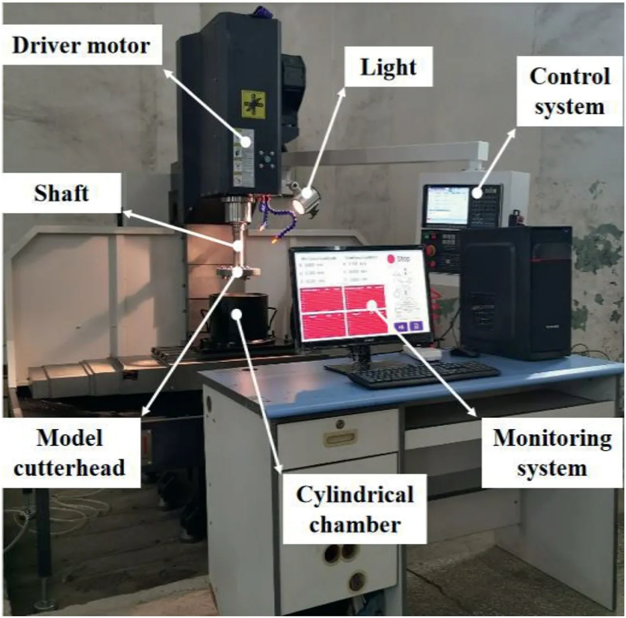
Fig.1.The newly developed WHU-SAT soil abrasion tester.
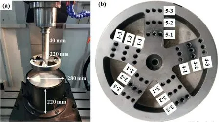
Fig.2.(a) The cylindrical chamber,and (b) The modelled cutterhead.
As shown in Fig.3,the modelled scraper consists of a cutter edge,cutter body and connecting bolt with lengths of 10 mm,10 mm and 40 mm,respectively.The front angle,back angle and edge angle can be changed by loosening the bolt to change the modelled scraper,which is favourable for exploring the effect of cutter shape on scraper wear.The modelled scraper retains the overall shape and simplifies the local feature of the shield scraper.As a result,not only can the contact state between the soil and tool be simulated,but also the wear mechanism of the cutting tool can be revealed.The scraper is connected to the cutterhead by bolts with a length of 40 mm.It allows the scraper to be easily removed and replaced.Since the modelled scraper is much lighter than the cutterhead,it can be weighed with a high-precision scale(0.001 g).Moreover,under the protection of the cutting tool,the replacement frequency of the modelled cutterhead can be minimized.It not only reduces the test cost but also simplifies the manufacturing process.Compared with existing tests,the advantages of the WHU-SAT test are the rational simulation of cutterhead structure and scraper characteristics,as well as the comprehensive and precise monitoring of tunnelling parameters.Details have been summarized by Tang et al.(2022).

Fig.3.Schematic diagram of the modelled scraper.α-Front angle;β-Back angle;γ-Edge angle.
2.2.The WHU-SAT soil abrasion test procedure
When the soil abrasion test is conducted,the new modelled scrapers are cleaned,dried and numbered.A high-precision electronic balance(0.001 g)is used to weigh the modelled scrapers.The weighed scrapers are installed on the modelled cutterhead in turn.Then,appropriate soil samples will be filled into the cylindrical chamber to a height of 180 mm.Compaction is performed whenever the thickness is increased by 50 mm.After preparing soil samples,the modelled cutterhead is installed at the bottom of the drive shaft.It penetrates soil samples according to preset working parameters such as rotation speedN=150 r/min,tunnelling speedV=20 mm/min,tunnelling depthh=140 mm and test timeT=60 min.When the tunnelling depth reachesh=140 mm,the modelled cutterhead will stop penetrating and continue rotating according to the preset rotation speed until the test time is exhausted.Then,the modelled scrapers are disassembled and cleaned to remove the muck on the metal surface.After being dried,the worn scrapers are weighed three times by a high-precision electronic balance (0.001 g).The scraper wear is quantified by the weight loss before and after the test.The position coordinates,rotation speed,tunnelling speed,motor power and cutterhead torque are detected by the monitoring system,which promotes the parametric study of the scraper wear process.
2.3.The quartz sand sample
The geological properties of natural sand are complex and changeable.When it is utilized as a soil sample,multiple physical and mechanical parameters are prone to change at the same time.Scraper wear results are susceptible to disturbance under the condition of uncontrollable variable parameters.To minimize the effect of uncertainty resulting from variable soil parameters,crushed quartz sand samples were utilized for the WHU-SAT tests.The same crusher was utilized to crush quartz with a purity of 99.75% to ensure that the sand particles had a good agreement in shape characteristics.Referring to the existing soil abrasion tests,the quartz stone is crushed into sand samples with particle sizes of 0.125-0.212 mm,0.212-0.425 mm,0.425-0.71 mm,0.71-1.18 mm,1.18-2.36 mm,2.36-3.35 mm and 3.35-4.75 mm.As shown in Fig.4,the mixed soil samples 1 and 2 can be obtained by uniformly mixing them in mass ratios of 1:1:2:2:2:2:2 and 1:1: 2 : 2: 2 : 4: 4,respectively.
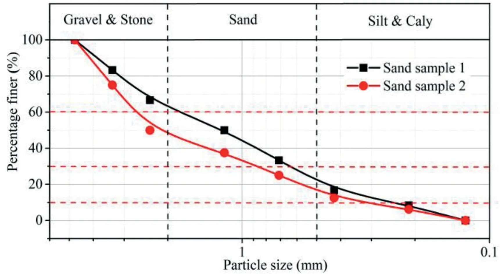
Fig.4.Particle gradation curves of soil samples.
3.Effect of cutter shape on scraper wear
06Cr19Ni10 and 45#have been widely used as cutter materials in existing tests such as PSAI,SGAT,SATC,RUB,BJTU and CUGB(Rostami et al.,2012;Jakobsen et al.,2013;Barzegari et al.,2015;Küpferle et al.,2018;Wu,2020;Wei et al.,2021).To compare with existing test results,the same materials were used in the present study (Fig.5).Their tensile strengths are 560 MPa and 580 MPa,while their elongation rates are 43% and 18%,respectively.Under the condition that their tensile strengths are similar,06Cr19Ni10 with a higher elongation rate consumes more energy than 45#when the same material mass is worn by sand particles.Details on their cutter angles are illustrated in Table 1.The modelled scrapers are installed in tool mounting holes by M8 screws.As shown in Fig.2,five tool mounting holes 5-1,2-2,4-2,1-3 and 3-3 are utilized for scraper installation.Two mounting holes share one number.They can be distinguished by L and R.L represents a scraper made of 06Cr19Ni10,while R represents that made of 45#.The corresponding installation diameters are 105,122,139,156 and 173 mm,respectively.The quartz sand used to analyse the effect of cutter angle on scraper wear is the mixed soil sample 1.
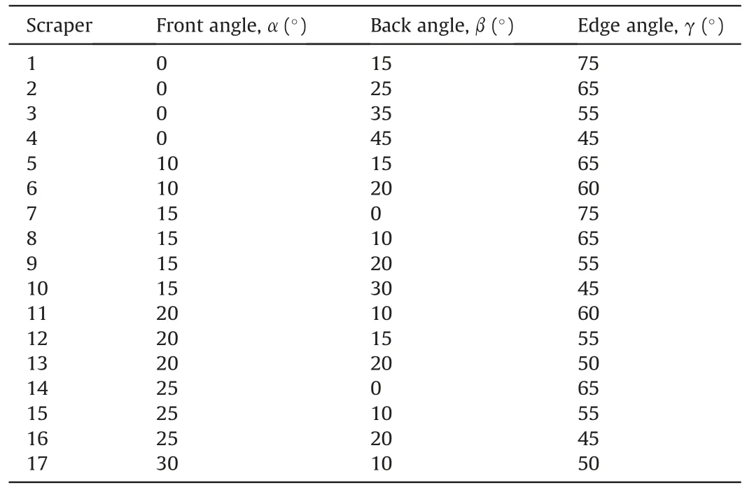
Table 1The front angles,back angles and edge angles of the modelled scrapers.
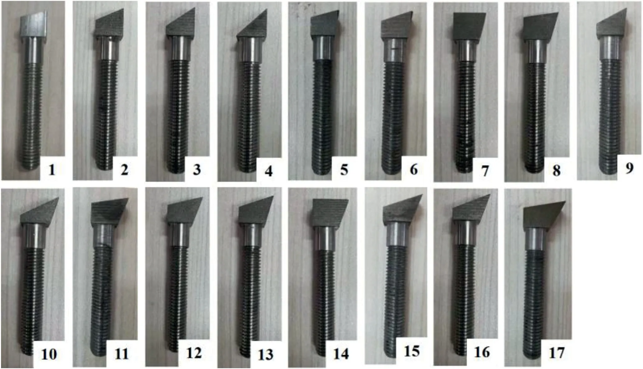
Fig.5.The modelled scrapers with various front angles,back angles and edge angles.
3.1.Variation in scraper wear with front angle
The variation in scraper wear with front angle is illustrated in Fig.6.When the back angle is β=10°(Fig.6a and b),the scraper wear decreases first and then increases with increasing front angle.The front angle of the modelled scraper with the best wear resistance is α=25°.This is related to the variation in cutting resistance and stress distribution verified by concrete cutting tests (Xu et al.,2021).When the front angle is α=0°,the front edge is perpendicular to the excavation surface.The cutting resistance along the sliding direction is too high to cause excessive wear.As the front angle increases to α=25°,the cutting resistance of the modelled scraper decreases.Hence,scraper wear decreases with increasing front angle.As the front angle continues to increase to α=30°,stress concentration will occur on the scraper edge due to the cutting resistance distributed on the smaller edge angle.Thus,scraper wear increases with increasing front angle.The outliers of the modelled scrapers with installation diameters ofD=105 mm are related to excessive weighing errors resulting from small wear extents or intense surface scratches with angular coarse particles.A similar phenomenon occurred in the subsequent analysis of scraper wear with the cutter angle.When the back angle is β=20°(Fig.6c and d),the variation trend of scraper wear with front angle agrees well with that in Fig.6a and b.The front angle of the modelled scraper with the best wear resistance is α=15°.
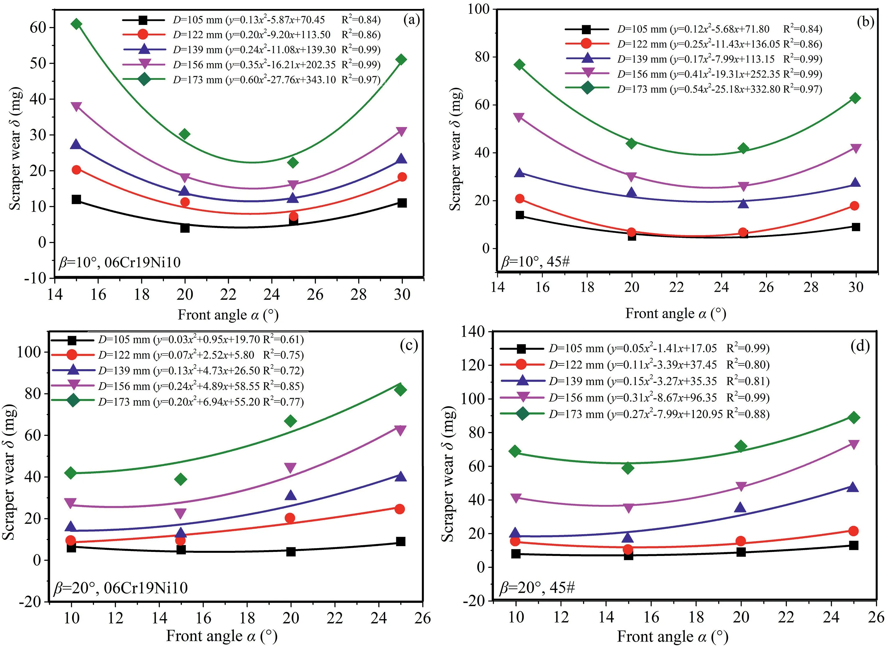
Fig.6.Variation in scraper wear with front angle under constant back angle.
Since scraper wear is related to cutting distance,installation diameter makes a significant contribution to the experimental results.As shown in Fig.7,the WHU-SAT test indicates that there is a positive correlation between them.The larger the installation diameter is,the greater the growth rate of scraper wear will be,which agrees well with the test results by Mou(2019).The variation in scraper wear with installation diameter is related to the increase in cutting area and residue deposition.Since the number of modelled scrapers for each installation diameter is the same,the excavation area of each scraper increases nonlinearly with increasing installation diameter.Under the intense squeezing and scratching of angular sand,the primary wear rate of the modelled scraper will increase.Moreover,sand particles move towards the chamber edge under the rotary cutting of the modelled cutterhead.The larger the installation diameter is,the greater the amount of residual sand will be.Under the repeated grinding and polishing of residue sand,the secondary wear rate of the modelled scraper will increase.Hence,the growth rate of scraper wear increases with the installation diameter.

Fig.7.Variation in scraper wear with installation diameter under constant back angle.
As shown in Fig.8a and b,when the edge angle is γ=55°,the scraper wear decreases with increasing front angle.This is related to the fact that cutting resistance decreases with increasing front angle,and there is no excessive stress concentration while the edge angle remains constant The front angle of the modelled scraper with the best wear resistance is α=25°.As shown in Fig.8c and d,when the edge angle is γ=65°,the variation trend of the scraper wear with the front angle agrees well with that in Fig.8a and b.The front angle of the modelled scraper with the best wear resistance is α=25°,which does not change with increasing edge angle.
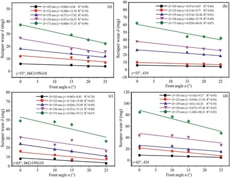
Fig.8.Variation in scraper wear with front angle under constant edge angle.
3.2.Variation in scraper wear with back angle
The variation in scraper wear with back angle is illustrated in Fig.9.When the front angle is α=0°(Fig.9a and b),the scraper wear decreases first and then increases with increasing back angle.It is related to the variation in frictional resistance and stress distribution.When the back angle is β=15°,the angle between the back edge and horizontal plane is small.Residual sand will grind and scratch the metal surface when flowing along the back edge.Hence,scraper wear is relatively severe under the condition of high frictional resistance.As the back angle increases to β=35°,scraper wear decreases under the condition that the frictional resistance of the residual sand to the back edge decreases.When the back angle continues to increase to β=45°,stress concentration will occur on the scraper edge due to the cutting resistance distributed on the smaller edge angle.Thus,scraper wear increases with increasing back angle.The back angle of the modelled scraper with the best wear resistance is β=35°.When the variation in scraper wear with installation diameter is depicted,the gradually increasing growth rate agrees well with that in Fig.7.
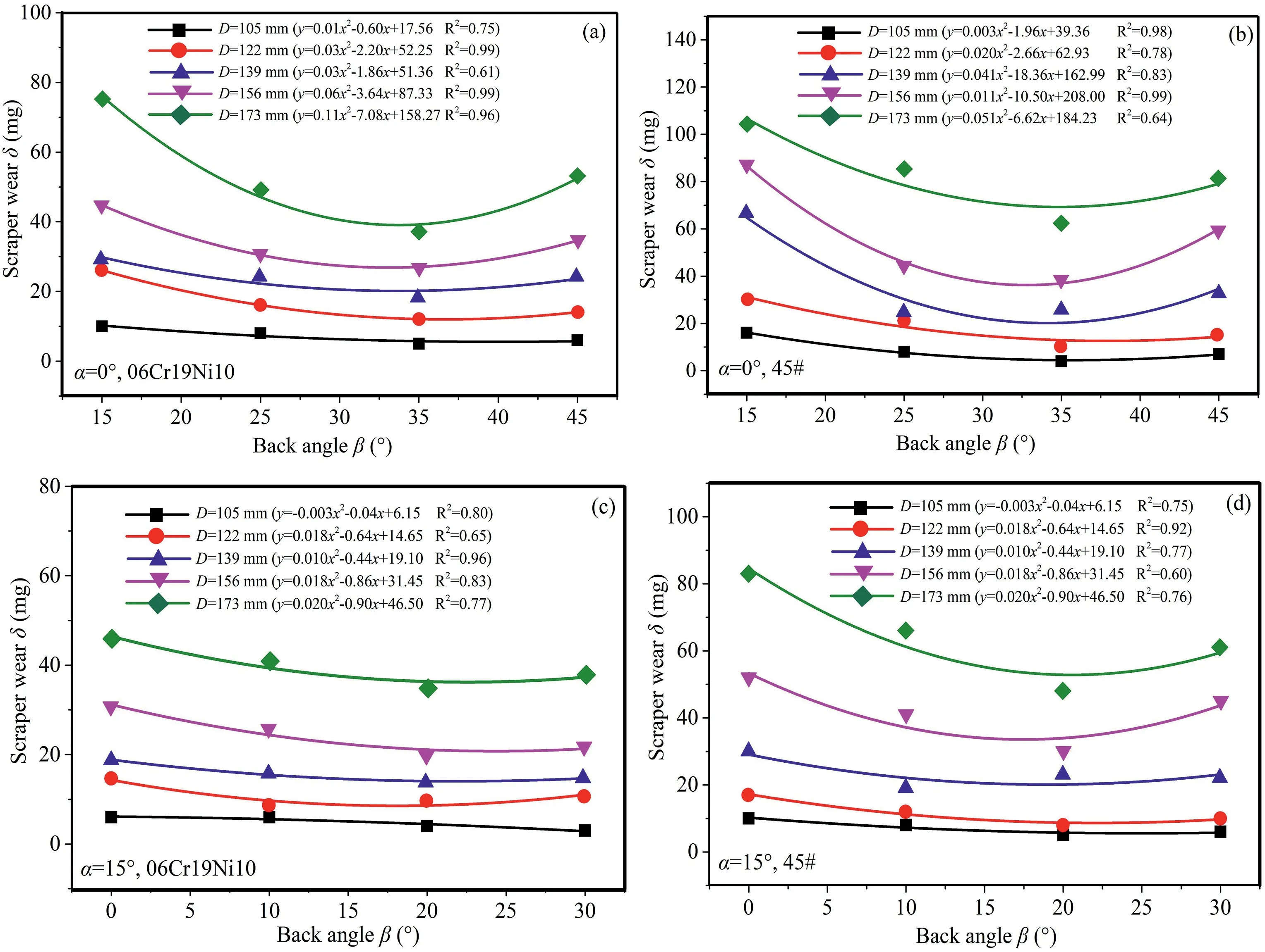
Fig.9.Variation in scraper wear with back angle under constant front angle.
When the front angle is α=15°(Fig.9c and d),the variation trend of scraper wear with back angle agrees well with that in Fig.9a and b.The back angle of the modelled scraper with the best wear resistance is β=20°,which decreases with increasing front angle.This is consistent with the angles of the modelled scraper with the best wear resistance in Fig.6c and d.Moreover,the experimental study was compared with the concrete cutting test conducted by Xu et al.(2021).The results indicate that when the front angle is α=15°,scraper wear decreases as the back angle increases from β=0°to β=20°.There is good consistency between the above two experimental tests.
When the edge angle is constant,the scraper wear increases with increasing back angle.This is related to the fact that the frictional resistance of the residual sand to the back edge increases,and there is no excessive stress concentration while the edge angle remains constant.As shown in Fig.10a and b,when the edge angle is γ=55°,the back angle of the modelled scraper with the best wear resistance is β=10°.This is consistent with the angles of the modelled scraper with the best wear resistance in Fig.6a and b.As shown in Fig.10c and d,when the edge angle is γ=65°,the variation trend of scraper wear with back angle agrees well with that in Fig.10a and b.The back angle of the modelled scraper with the best wear resistance is β=0°,which decreases with increasing edge angle.They are consistent with the angles of the modelled scraper with the best wear resistance in Fig.8c and d.
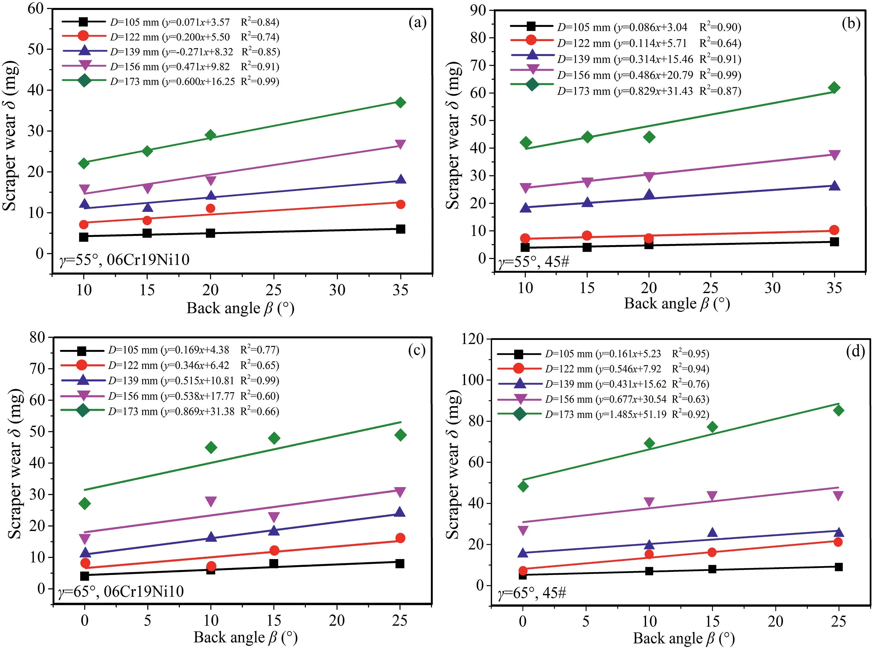
Fig.10.Variation in scraper wear with back angle under-constant edge angle.
3.3.Variation in scraper wear with edge angle
The variation in scraper wear with edge angle is illustrated in Fig.11.When the front angle is α=0°(Fig.11a and b),the scraper wear decreases first and then increases with increasing edge angle.This is related to the variation in the stress distribution and frictional resistance.When the edge angle is γ=45°,stress concentration is prone to occur on the scraper edge due to the cutting resistance distributed on the smaller edge angle.Scraper wear is relatively severe under the condition of stress concentration.As the edge angle increases to γ=55°,scraper wear decreases under the condition that the stress concentration is relieved.As the edge angle continues to increase to γ=75°,the angle between the back edge and the horizontal plane decreases to β=15°.Scraper wear increases under the condition that the frictional resistance of the residue sand to the back edge increases significantly.The edge angle of the modelled scraper with the best wear resistance is γ=55°.This is consistent with the angles of the modelled scraper with the best wear resistance in Fig.9a and b.When the front angle is α=15°(Fig.11c and d),the variation trend of scraper wear with edge angle agrees well with that in Fig.11a and b.The edge angle of the modelled scraper with the best wear resistance is γ=55°,which does not change with increasing front angle.They are consistent with the angles of the modelled scraper with the best wear resistance in Fig.6c and d.When the variation in scraper wear with installation diameter is depicted,the gradually increasing growth rate agrees well with that in Fig.7.
When the back angle is constant,the scraper wear decreases first and then increases with increasing edge angle.This is related to the variation in the stress distribution and cutting resistance.When the edge angle is γ=50°,the stress concentration is prone to induce excessive scraper wear.As the edge angle increases to γ=55°,scraper wear decreases with the alleviation of stress concentration.When the edge angle continues to increase to γ=65°,the front edge decreases to α=15°.Scraper wear increases under the condition that the cutting resistance increases significantly.As shown in Fig.12a and b,when the back angle is β=10°,the edge angle of the modelled scraper with the best wear resistance is γ=55°.They are consistent with the angles of the modelled scraper with the best wear resistance in Fig.6a and b.As shown in Fig.12c and d,when the back angle is β=20°,the variation trend of scraper wear with edge angle agrees well with that in Fig.12a and b.The edge angle of the modelled scraper with the best wear resistance is γ=55°,which does not change with increasing front angle.They are consistent with the angles of the modelled scraper with the best wear resistance in Fig.6c and d.
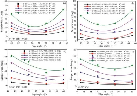
Fig.12.Variation in scraper wear with edge angle under constant back angle.
3.4.Optimisation of scraper shape
As shown in Figs.11 and 12,when the blade angle is γ ≥55°,scraper wear decreases with decreasing front angle and back angle.The scraper wear resistance can be improved by reducing the edge angle.When the edge angle is γ<55°,scraper wear increases with decreasing edge angle.It is not feasible to improve the scraper wear resistance by reducing the edge angle.The edge angle of the modelled scraper with the best wear resistance is γ=55°.As shown in Fig.8,when the edge angle is γ=55°,the corresponding front angle of the modelled scraper with the best wear resistance is α=25°.The optimal angles of the modelled scraper are compared with the actual angles of the shield scraper.As shown in Table 2,the results indicate that the actual angles for abrasive sandy ground are α=20°-28°and γ=53°-60°.The optimal angles of the modelled scraper are within the range of the actual angles of the shield scraper.

Table 2The front angles,back angles and edge angles of the welded scrapers.
4.Effect of metal material on scraper wear
As shown in Fig.13,the front angle and back angle of the modelled scrapers with various metal materials are α=0°and β=15°,respectively.Details on the chemical composition of the metal materials are illustrated in Table 3.The tool mounting holes and quartz sand samples are consistent with those in Section 3.
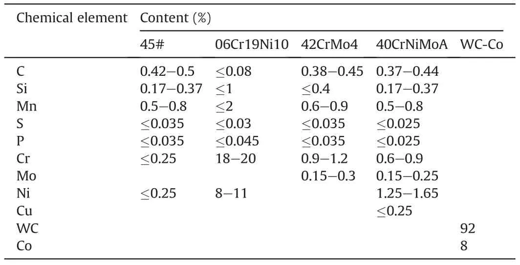
Table 3The chemical composition of 45#,06Cr19Ni10,42CrMo4,40CrNiMoA and WC-Co.
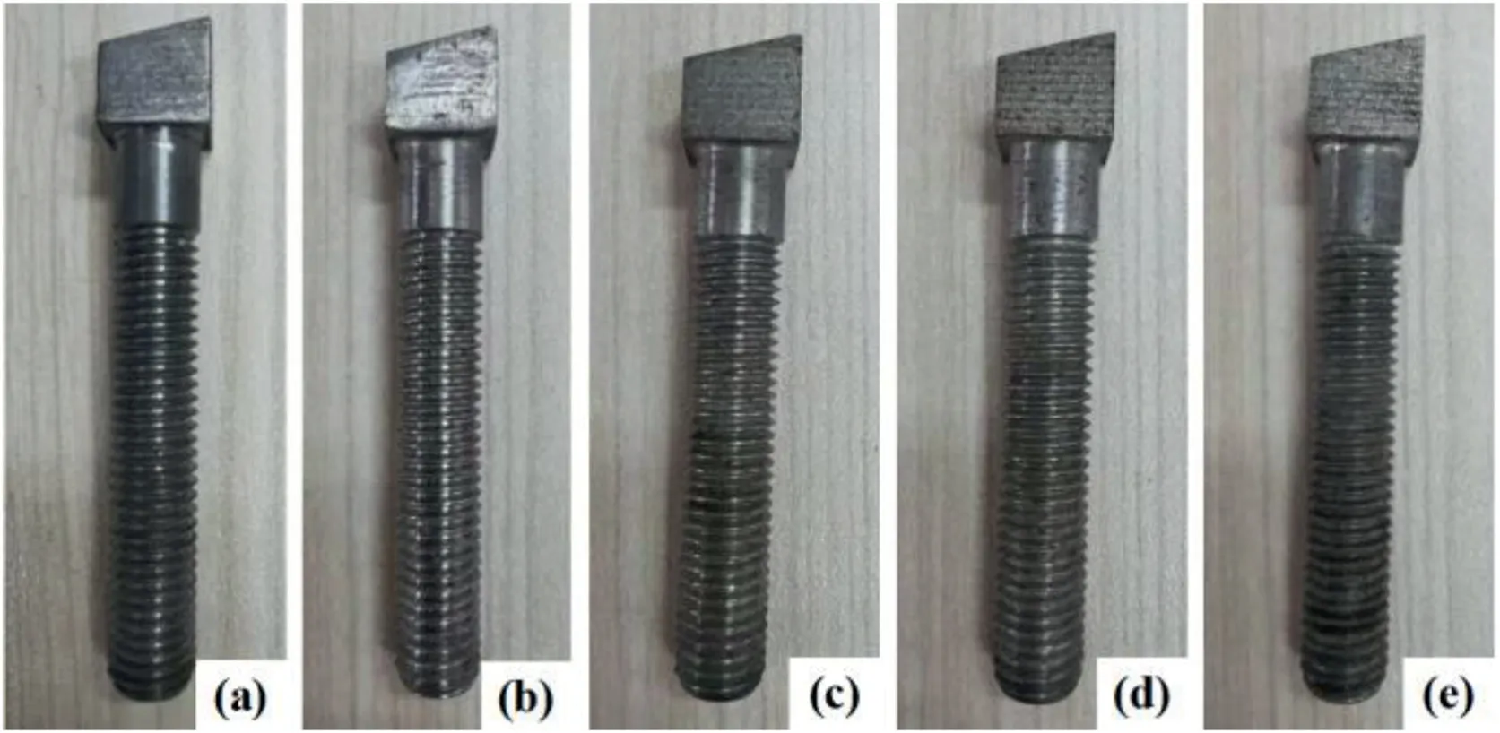
Fig.13.The modelled scrapers with various metal materials: (a) 45#,(b) 06Cr19Ni10,(c) 42CrMo4,(d) 40CrNiMoA,and (e) WC-Co.
4.1.Variation in scraper wear with metal material
The variation of scraper wear with metal material is illustrated in Fig.14.The wear of the scraper made of 45# is the largest,followed by the wear of scrapers made of 06Cr19Ni10,42CrMo4 and 40CrNiMoA.The wear of the scraper made of WC-Co is the smallest.The wear resistance of scrapers made of the above five metal materials is generally increased.The relative wear resistance of 06Cr19Ni10,42CrMo4 and 40CrNiMoA agrees well with the mechanism study by Chen (2012) and that of 45# and WC-Co is consistent with the experimental results by Wu(2020).The outliers of the modelled scrapers made of 40CrNiMoA with installation diameters ofD=105 mm and 139 mm are related to the several deep scratches of angular coarse particles.This can be verified by scratch analysis on the scraper surface.As shown in Fig.15,the scratches on the above two scrapers made of 40CrNiMoA are generally deeper and wider than those of the others.
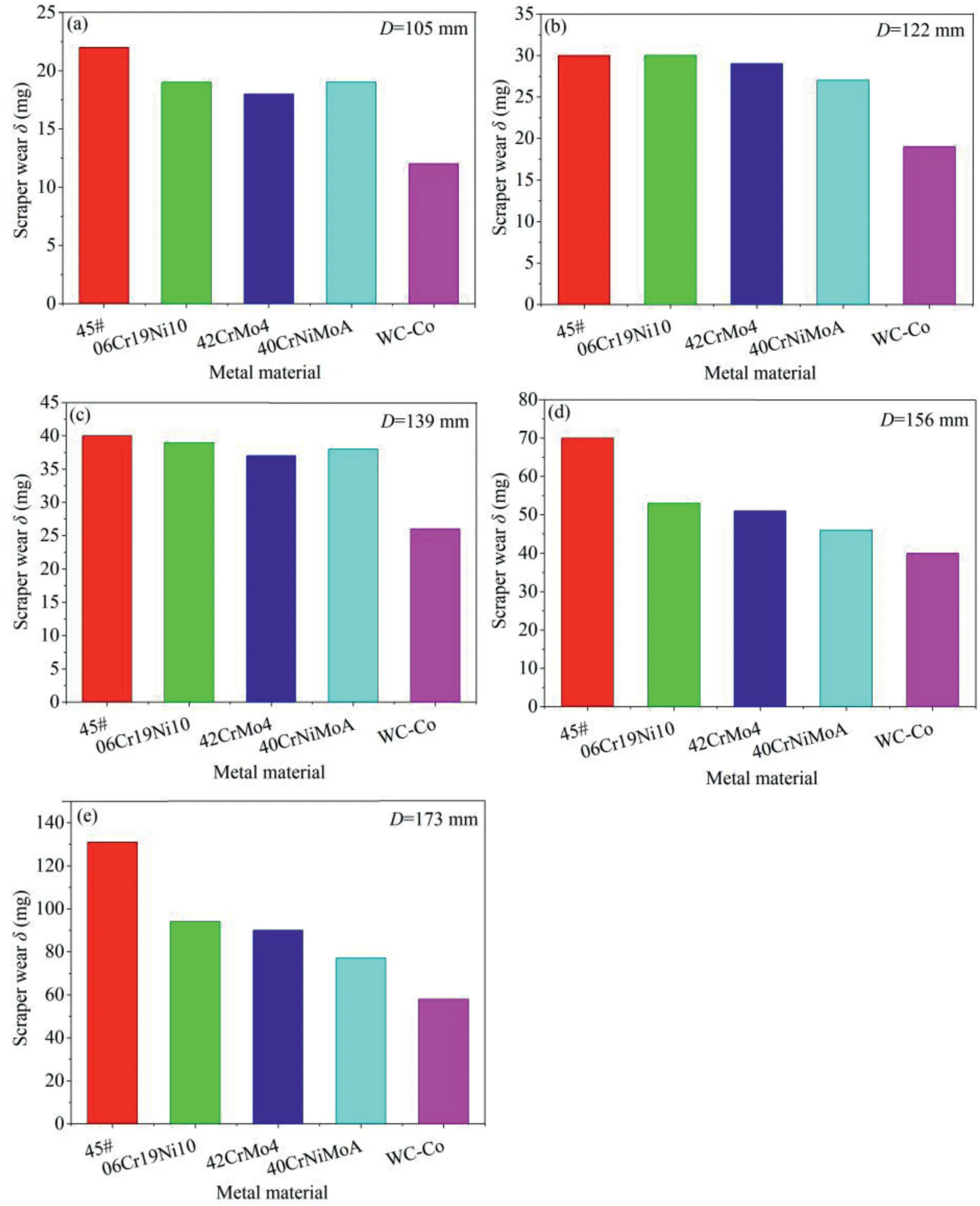
Fig.14.Variation in scraper wear with metal material.

Fig.15.The microscope photographs of modelled scrapers made of 40CrNiMoA taken with the GAOSUO digital microscope:(a)D=105 mm,(b)D=122 mm,(c)D=139 mm,(d)D=156 mm,and (e) D=173 mm.
The variation in scraper wear with metal material is related to the chemical elements and microstructure.The chemical elements of 06Cr19Ni10 are the same as those of 45#,but the content of Cr and Ni is higher,which improves the plastic capacity (Wang et al.,2014).The microstructure of 42CrMo4 is tempered sorbite,which has better wear resistance than 06Cr19Ni10 with an austenite microstructure (Habig,1980).Compared with 42CrMo4,the lower content of S and P makes 40CrNiMoA tougher(He and Wang,2001).Moreover,the addition of Ni promotes 40CrNiMoA with a higher yield strength.WC-Co has a higher compressive strength and wear resistance than the above four materials due to its dense hexagonal microstructure(Khmyrov et al.,2017;Küpferle et al.,2017).Hence,the wear resistance of modelled scrapers made of the above five metal materials increases in turn.In addition to metal material,scraper wear is also related to installation diameter.As shown in Fig.16,scraper wear and its growth rate increase with increasing installation diameter,which agrees well with that in Fig.7.
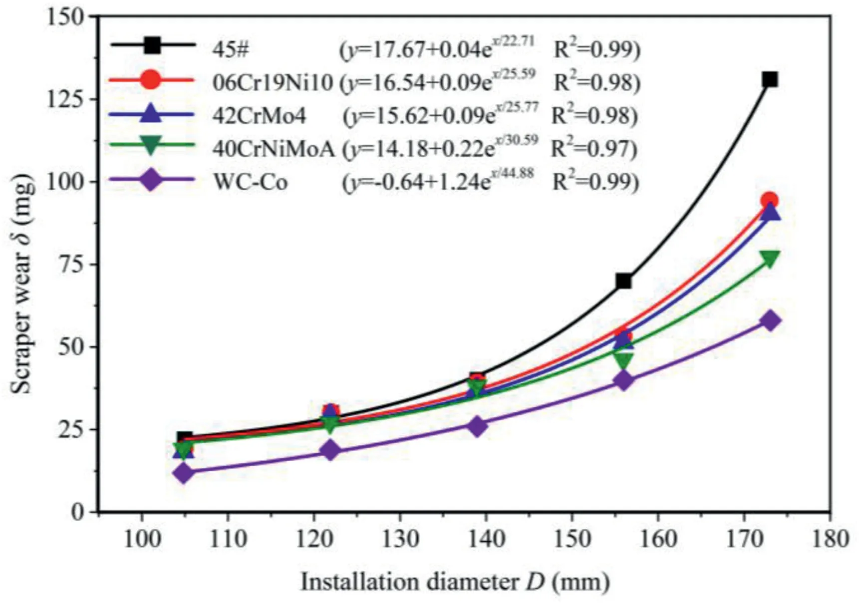
Fig.16.The wear extent of scrapers made of different metal materials varying with installation diameter.
4.2.Evaluation of relative wear resistance
The relative wear coefficient (defined as the ratio of the reciprocal of scraper wear) has been proposed to quantify the relative wear resistance of the modelled scrapers made of different materials.The calculation equation can be expressed as
whereRWCis the relative wear coefficient of the scraper made of metal materialato that made of metal materialb;δais the wear of the scraper made of metal materiala;and δbis the wear of the scraper made of metal materialb.
As shown in Table 4,the relative wear resistance coefficients of scrapers made of 45#,06Cr19Ni10,42CrMo4 and 40CrNiMoA to those made of WC-Co were calculated.The results indicate that they are distributed in the ranges of 0.443-0.65,0.617-0.755,0.644-0.784 and 0.634-0.87,with average values of 0.569,0.661,0.691 and 0.728,respectively.This means that the wear resistance of scrapers made of 45#,06Cr19Ni10,42CrMo4 and 40CrNiMoA is 56.9%,66.1%,69.1%and 72.8%of that made of WC-Co,respectively.
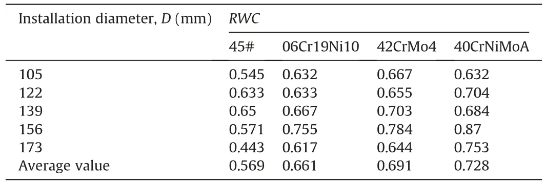
Table 4The RWC of scrapers made of 45#,06Cr19Ni10,42CrMo4 and 40CrNiMoA to scrapers made of WC-Co.
4.3.Optimisation of metal materials
Since the wear resistance of WC-Co is much better than those of the other four metal materials,it is recommended as a metal material for the modelled scraper cutting quartz sand samples.The metal material of the modelled scraper was compared with that of the shield scraper.The results indicate that WC-Co has been utilized as a shield scraper material for abrasive sandy ground tunnels such as the Nanjing Yangtze River Tunnel (Min et al.,2015),Sanyanglu Metro Tunnel (Huang et al.,2018) and Sutong GIL Yangtze River Crossing Cable Tunnel (Zhang et al.,2021a).The metal material of the modelled scraper agrees well with that of the shield scraper.
5.Effect of alloy hardness on scraper wear
As shown in Fig.17,the modelled scrapers are made of 45#and 42CrMo following the Chinese standard,which corresponds to ASTM 1045 and AISI 4140 following the ASTM standard and C45(1.0503)and 42CrMo4 following the EU standard.Their front angle and back angle are α=0°and β=15°.Details on the chemical composition are illustrated in Table 2.The alloy hardness can be changed by heat treatment.For instance,the modelled scrapers with Rockwell hardness(HRC)values of 24,32,38,47,51,55,58 and 62 are obtained from standard metal materials 45#and 42CrMo by quenching and tempering at different temperatures.The heat treatment process is determined according to the standard of the China code for quenching and tempering of steel parts (GB/T 16924-2008,2008).The tool mounting holes are consistent with those in Section 3.The quartz sand utilized in this test is mixed soil sample 2.
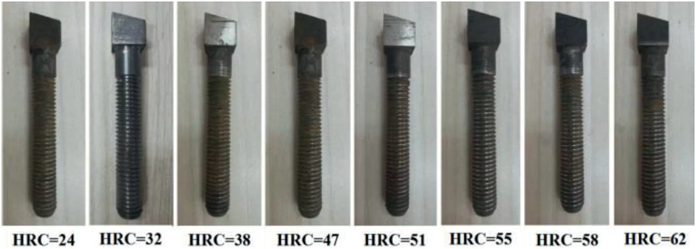
Fig.17.The modelled scrapers with Rockwell hardness (HRC) values of 24,32,38,47,51,55,58 and 62.
5.1.Variation in scraper wear with alloy hardness
As shown in Fig.18,when the variation of scraper wear with installation diameter is depicted,an inverted S-shaped curve is formed.Taking the modelled scrapers with installation diameters ofD=173 mm as an example,when the alloy hardness isHRC=24,the wear extents of scrapers made of 45#and 42CrMo4 are 126 mg and 107 mg,respectively.As the alloy hardness increases toHRC=47,the wear extent of scrapers made of 45# and 42CrMo4 decreases slowly to 106 mg and 77 mg.Scraper wear is insensitive to alloy hardness.When the alloy hardness increases toHRC=58,the curve experiences a jump,and the scraper wear decreases rapidly to 51 mg and 37 mg,respectively.The Rockwell hardness interval ofHRC=[47,58]is the so-called sensitive hardness interval in abrasive wear mechanisms (Zhang et al.,2021a).As the alloy hardness continues to increase further above the upper limit of the sensitive hardness interval and reachesHRC=62,the wear extent of scrapers made of 45# and 42CrMo4 decreases slowly to 45 mg and 29 mg,respectively.Scraper wear is insensitive to alloy hardness.The outliers of scrapers with alloy hardness ofHRC=38 are related to the surface polishing treatment,which slightly increasesmetal wear resistance.The WHU-SAT tests have been compared with similar MSTS tests(Zhang et al.,2021a).The general variation trend of scraper wear with alloy hardness agrees well,while the upper limit of the sensitive hardness interval of the WHU-SAT is larger than that of the MSTS.This is related to the higher quartz content of sand samples in the WHU-SAT than that in the MSTS.In addition to alloy hardness,scraper wear is also related to installation diameter.As shown in Fig.19,scraper wear and its growth rate increase with increasing installation diameter,which agrees well with that in Fig.7.
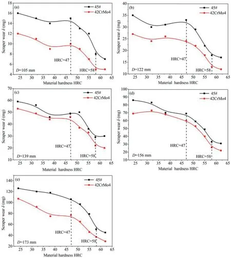
Fig.18.Variation in scraper wear with alloy hardness.
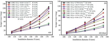
Fig.19.The wear extent of scrapers with different alloy hardnesses varying with installation diameter.
5.2.Wear mechanism of modelled scraper
The tribological mechanism can be utilized to explain the sensitive hardness interval observed in Fig.18.According to Alavi Gharahbagh et al.(2013b),Mosleh et al.(2013),Barzegari et al.(2015) and Zhang et al.(2021a),cutting tool wear in quartz sand is mainly abrasive wear,in which the relative hardness of worn material compared to that of abrasive particles plays an important role in the wear extent.When the hardness of worn material is less than 50%that of abrasive particles(He and Wang,2001;Jian et al.,2016;Zhang et al.,2018),the penetration depth of asperities on the latter into the former is large.Once relative sliding occurs at the contact surface,the wear extent remains at a high level.When the hardness of worn material increases to approximately 50%-80%that of abrasive particles (Bystrov,2013;Bialobrzeska and Kostencki,2015;Jian et al.,2016),the penetration depth of asperities on the abrasive particle into the worn material decreases rapidly.As a result,abrasive wear decreases rapidly with increasing alloy hardness.With a further increase in the hardness of worn material to more than 80% of that for abrasive particles (Lin et al.,2018;Zhang et al.,2018),the penetration depth of asperities on the abrasive particle into the worn material is small.Microcutting mainly occurs on the surface of the worn material.As a result,abrasive wear remains at a low level,reflecting the transition law from high to low wear levels (Alavi Gharahbagh et al.,2013b;Mosleh et al.,2013;Zhang et al.,2021a).
For this experimental study,the modelled scraper and quartz sand are worn material and abrasive particles in the soil-tool tribological system.According to Alavi Gharahbagh et al.(2013b),the Vickers hardness of quartz is approximatelyHV=1123(corresponding to the Rockwell hardness ofHRC=71).When the alloy hardness isHRC=[24,47](approximately 34%-66%of quartz hardness),microscope photographs indicate that the scratch depth of sand asperities to the scraper surface remains at a high level(Fig.20).Especially when the alloy hardness isHRC=24 and 32,deep failure zones occur on the metal surface of the modelled scrapers.The modelled scraper undergoes severe microcutting from sand asperities.Scraper wear is high and insensitive to alloy hardness.When the alloy hardness increases toHRC=[47,58](approximately 66%-82% of quartz hardness),there are mainly middle and shallow scratches occurring on the cutter surface(Fig.20).The penetration depth of sand asperities to the scraper surface decreases rapidly.The modelled scraper undergoes weakened microcutting from sand asperities.As a result,scraper wear decreases rapidly with increasing alloy hardness.The sensitive hardness interval of the modelled scraper isHRC=[47,58],which is in the range of 50%-80%of quartz hardness.The scraper wear test agrees well with the abrasive wear mechanism.As the alloy hardness continues to increase toHRC=[58,62](approximately 82%-87% of quartz hardness),there are mainly shallow scratches occurring on the cutter surface (Fig.20).The penetration depth of sand asperities to the scraper surface remains at a low level.Themodelled scraper undergoes slight microcutting from sand asperities.As a result,scraper wear is low and insensitive to alloy hardness.
5.3.Optimisation of alloy hardness
According to the Gurland relationship,hardness and toughness are mutually restrained (Zhang et al.,2021a).The higher the hardness is,the lower the toughness will be.When the modelled cutterhead tunnelling in quartz sand samples,scraper wear can be reduced by increasing alloy hardness.However,when excessively hard scrapers with low toughness collide with coarse quartz particles,cutter edges are prone to crack under severe impact.Cutterhead inspection and tool maintenance resulting from abnormal wear are critical factors restricting tunnelling efficiency.Scrapers with high toughness should be selected as much as possible on the premise that the hardness meets the wear resistance requirements.
Regarding the present soil abrasion test,when the alloy hardness isHRC=[47,58],scraper wear decreases rapidly with increasing alloy hardness.It is effective in reducing the scraper wear by increasing alloy hardness.However,as the alloy hardness increases toHRC=[58,62],scraper wear is small and insensitive to the alloy hardness.It is inappropriate to continue to decrease scraper wear by increasing alloy hardness.The recommended hardness interval for the excavation of quartz sand samples is considered to beHRC=[58,62].Thus,not only can scraper wear be significantly reduced but cutter edge cracking resulting from the continuous increase in alloy hardness can also be alleviated.
6.Conclusions
In the present study,the newly developed WHU-SAT soil abrasion test was used to evaluate the variation in scraper wear with geometry,material and hardness.The influence mechanism of cutter parameters on scraper wear has been revealed by analysing the scratch characteristics of the scraper surface.Cutter geometry and material parameters have been optimised to reduce scraper wear.The present study provides a reference for optimising scraper geometry and material parameters.From the present study,the following conclusions can be drawn:
(1) The influence of cutter geometry on scraper wear is related to the stress state.Increases in the front angle,back angle and edge angle decrease the cutting resistance,frictional resistance and stress concentration,respectively.The optimal front angle,back angle and edge angle for quartz sand are α=25°,β=10°and γ=55°.
(2) The wear of scrapers made of 45#,06Cr19Ni10,42CrMo4,40CrNiMoA and WC-Co decreases in turn.It is related to the chemical elements and microstructure of the metal material.The wear resistance of scrapers made of the first four metal materials is 56.9%,66.1%,69.1%and 72.8%of that of scrapers made of WC-Co.
(3) The hardness and toughness are mutual restraints.It is necessary for manufacturers to modulate the hardness to just slightly above the upper limit of the sensitive hardness interval.Hence,the modelled scrapers with hardness intervals ofHRC=[58,62] are recommended for the excavation of quartz sand samples.
The soil sample utilized in the present study is crushed quartz sand.The variation in scraper wear with geometry and material parameters should be validated with more natural sand samples in future studies.
Declaration of competing interest
The authors declare that they have no known competing financial interests or personal relationships that could have appeared to influence the work reported in this paper.
Acknowledgments
The support provided by the National Natural Science Foundation of Youth Fund Project of China (Grant No.52308415),Key Research and Development Program of Hubei Province,China(Grant No.2021BCA154) and Natural Science Foundation of Hubei Province,China (Grant No.2021CFA081) is gratefully acknowledged.
Abbreviations
TBM Tunnel boring machine
PSAI Penn state soil abrasion tester
SGAT Soft ground abrasion tester
SATC Soil abrasion testing chamber
RUB Ruhr-University Bochum tester
CUGB China University of Geosciences (Beijing) tester
BJTU Beijing Jiaotong University tester
MSTS Multifunctional shield test system
WHU-SAT Soil abrasion tester developed by Wuhan University
杂志排行

Journal of Rock Mechanics and Geotechnical Engineering的其它文章
- Determination of uncertainties of geomechanical parameters of metamorphic rocks using petrographic analyses
- Evaluation of excavation damaged zones (EDZs) in Horonobe Underground Research Laboratory (URL)
- On the calibration of a shear stress criterion for rock joints to represent the full stress-strain profile
- Effect of dynamic loading orientation on fracture properties of surrounding rocks in twin tunnels
- Effect of fracture fluid flowback on shale microfractures using CT scanning
- Mechanical behaviour of fiber-reinforced grout in rock bolt reinforcement