Mechanical responses of anchoring structure under triaxial cyclic loading
2024-02-29PengWngNongZhngQunWeiXinglingXuGungzhenCuiAornLiSenYngJigungKn
Peng Wng ,Nong Zhng,b ,Qun Wei ,Xingling Xu ,Gungzhen Cui ,Aorn Li ,Sen Yng,Jigung Kn,*
a State Key Laboratory of Coal Resources and Safe Mining,School of Mines,China University of Mining and Technology,Xuzhou,221116,China
b School of Civil Engineering,Xuzhou University of Technology,Xuzhou,221116,China
c School of Mechanical Engineering,Jiangsu University of Technology,Changzhou,213001,China
Keywords:Triaxial stress Dynamic-static combination load Cyclic loading Anchoring structure (AS)Cumulative damage
ABSTRACT Dynamic load on anchoring structures(AS) within deep roadways can result in cumulative damage and failure.This study develops an experimental device designed to test AS under triaxial loads.The device enables the investigation of the mechanical response,failure mode,instability assessment criteria,and anchorage effect of AS subjected to combined cyclic dynamic-static triaxial stress paths.The results show that the peak bearing strength is positively correlated with the anchoring matrix strength,anchorage length,and edgewise compressive strength.The bearing capacity decreases significantly when the anchorage direction is severely inclined.The free face failure modes are typically transverse cracking,concave fracturing,V-shaped slipping and detachment,and spallation detachment.Besides,when the anchoring matrix strength and the anchorage length decrease while the edgewise compressive strength,loading rate,and anchorage inclination angle increase,the failure intensity rises.Instability is determined by a negative tangent modulus of the displacement-strength curve or the continued deformation increase against the general downward trend.Under cyclic loads,the driving force that breaks the rock mass along the normal vector and the rigidity of the AS are the two factors that determine roadway stability.Finally,a control measure for surrounding rock stability is proposed to reduce the internal driving force via a pressure relief method and improve the rigidity of the AS by full-length anchorage and grouting modification.
1.Introduction
Dynamic loads have become increasingly pronounced during underground coal mining as coal is mined at greater depths,which causes significant damage to roadways and support systems,and increases the difficulty of maintaining the anchoring structure(AS).Continuous fatigue damage is commonly observed in the AS of support systems in roadways due to the disturbance of cyclic load in high static load environments(ˇSnupárek and Konecný,2010;He et al.,2023;Kang et al.,2023).Therefore,it is crucial to understand the mechanical response and fragmentation mechanism of AS under the dynamic loading condition.
In China,bolt support is widely used to control the stability of the roadway.The AS consists of three components(bolt,anchoring agent,and surrounding rock) and two interfaces (the boltanchoring agent interface and the surrounding rock-anchoring agent interface) (Belghali et al.,2017;Feng et al.,2018;Yu,2014).Some studies have investigated the fracture damage constitutive model of anchored intermittently jointed rocks under tension and shear based on the theories of fracture and damage mechanics to clarify the toughening and crack arrest effects of the bolt (Li et al.,2022a;Yang et al.,2021;Feng et al.,2022;Zhang et al.,2022).Under uniaxial compression,the splitting of the rock mass on both sides is the major failure mode of the AS(Wu et al.,2020;An et al.,2021).A prestressed rock mass initially expands and then shrinks due to the influence of corrosion as the pitting corrosion rate rises during a shear test (Ding et al.,2022).Besides,fatigue loading can increase the strength of an anchored rock mass,and static loading has a cumulative effect on the strength deterioration of the specimen (Li et al.,2022b).The shear energy loss ratio of the energyabsorbing rock generally ranges from 50% to 80% under cyclic shear loading(Wu et al.,2018;He et al.,2022).In a split Hopkinson pressure bar(SHPB)test,the vibration failure between the bolt and the surrounding rocks in AS under dynamic loading exhibits an apparent time lag effect(Qiu et al.,2022).Under tensile stress,the AS is highly correlated to the amplitude of the loading angle of dynamic loading (Zhou et al.,2013).In the cyclic pull-out test,the crack of the anchored interface propagates from the anchorage head to the anchorage end(Wang et al.,2023).Under the action of multiple stress,the roof occurrence,fragmentation of surrounding rocks,and pre-tightening stress are all significant factors that contribute to the failure of AS (Han et al.,2019;Jing et al.,2020;Wang et al.,2022).The shear slip and stress distribution of the AS can be well understood via numerical simulation(Wang et al.,2017;Sun et al.,2022).Recently,different facilities e.g.,one-dimensional(1D) dynamic-static loading test device (Li et al.,2009),twodimensional (2D) dynamic-static loading test device using the Instron electro-hydraulic servo testing machine (Zuo et al.,2007),single and bi-directional restrained pendulum-type impact dynamic loading test device(Zhao et al.,2019),and three-dimensional(3D) testing system for true triaxial dynamic-static loading (Su et al.,2017;Gong et al.,2018;Zhang et al.,2021),are employed to explore the fragmentation mechanism of different rocks under dynamic-static cyclic loads.The axial static stress and number of loading cycles significantly influence the strength,deformation modulus,and energy dissipation parameters of sandstone(Jin et al.,2020).Under cyclic loading with different stress amplitudes,the failure of red sandstone specimens is dominated by shear damage,and the rock burst occurs with a larger disturbance amplitude(Zhou et al.,2015).With the increase in the number of load cycles,the cumulative damage of coal sample shows an inverted “S" cumulative growth pattern.When the ratio of horizontal restraint to axial restraint stress is equal,the coal sample is less likely to be damaged (Ji et al.,2023).The threshold values of the axial static stress,the third principal stress,and the disturbance load amplitude of granite samples that exhibit rock burst damage under lowfrequency cyclic dynamic axial loading were studied by (Su et al.,2016).Unfortunately,many studies have focused on only unidirectional stress experiments and numerical simulations,the cumulative damage and fragmentation mechanism of AS should be further studied,especially to support the design of the control technologies.
This study utilized a fatigue testing machine that can apply dynamic and static loads and investigated the mechanical response and fragmentation mechanism of AS under practical stress paths under five working conditions: different anchoring matrix strengths,different anchorage modes,different edgewise compressive strengths,different loading rates,and different anchorage angles.The mechanical characteristics,failure mode,and instability criteria of the AS in the static load-cyclic dynamic load experiment were analyzed,and then a support control strategy was proposed.The supporting effect was verified by a case study of a deep roadway under dynamic loading in a coal mine after repair and reinforcement.
2.Methodology
2.1.Specimen preparation
The in situ stress of AS is shown in Fig.1a.The rock-like material(cement mortar) was used for the AS to ensure the reliability and reproducibility of the experimental results.The tested cement:sand ratios were 1:5.5(matrix UCS=10 MPa),1:4.5(15 MPa),and 1:3.5 (20 MPa).The experimental bolts were 304 stainless steel screws with a diameter of 6 mm.The supporting trays were 304 stainless steel plates with a size of 23 mm × 23 mm × 3 mm.Bar glue was selected as the anchoring agent.The rock specimens had a size of 100 mm×100 mm×100 mm,with a hole diameter of 7 mm at a depth of 90 mm.The working conditions for the AS specimens covered five categories,and the specific parameters were as follows:
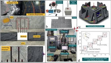
Fig.1.Schematic diagram of test work:(a)AS field working conditions,(b)Specimen preparation,(c)Triaxial test device,(d)Stress loading path,and(e)Experimental equipment.
(1) The different anchoring matrix strengths were 10 MPa,15 MPa and 20 MPa.Other parameters included the end anchorage,the edgewise compressive strength (2 MPa),the loading rate(30 mm/min),and the anchorage angle(90°and intersected with vertical stress).
(2) The different anchorage modes were no anchorage (BJM),end anchorage (DM),lengthened anchorage (JCM),and fulllength anchorage (QCM).Other parameters included the matrix strength (10 MPa),the edgewise compressive strength (2 MPa),the loading rate (30 mm/min),and the anchorage angle (90°),with the end anchorage,lengthened anchorage and full-length anchorage lengths of 30 mm,60 mm and 90 mm,respectively.
(3) The different edgewise compressive strengths were 1 MPa,2 MPa,and 3 MPa.Other parameters included the anchoring matrix strength (10 MPa),the end anchorage,the loading rate(30 mm/min),and the anchorage angle (90°).
(4) The different loading rates were 6 mm/min,30 mm/min,and 60 mm/min.Other parameters included the anchoring matrix strength (10 MPa),the end anchorage,the edgewise compressive strength (2 MPa),and the anchorage angle(90°).
(5) The different anchorage angles were 90°,75°,60°,and 45°.Other parameters included the anchoring matrix strength(10 MPa),the end anchorage,the edgewise compressive strength (2 MPa),and the loading rate (30 mm/min).The preparation steps of the specimens are shown in Fig.1b.
2.2.Test method
The experimental system included the primary loading test system,triaxial loading test system,and data monitoring devices.The dynamic and static load fatigue test machine in the State Key Laboratory of China University of Mining and Technology was selected as the loading test system.The self-designed triaxial loading test device for AS comprised a base unit,a sample holding unit,a lateral static load unit,and a top dynamic load unit.All components were combined together to achieve a triaxial dynamic-static loading environment for the small AS specimens constrained on 5 faces but free on the remaining face.The stress path loaded on the upper part of a small AS specimen could be accurately constructed with this testing machine to ensure that the experimental model was identical to the field condition.The face where the support bodies were located was marked as the free face,and the left side of the AS specimen was in close contact with the left vertical plate.Then,the ultrathin hydraulic cylinder was adjusted to apply different lateral static loads on the loading plate that was connected to the side and rear of the AS specimen through the loading headpin.Finally,the triaxial dynamic-static loading test was performed as shown in Fig.1c.
According to the stresses and site-specific situation at the coal mine,the dynamic strain rate in this test was determined by the categorization standards different from those of traditional rock mass dynamics (Gholipour and Billah,2022;Kumar et al.,2022).Herein,the load with a strain rate larger than 10-3/s was defined as the coal mine dynamic load (He et al.,2016),therefore,the anchorage stress environment of the underground roadway of the coal mine was set as a high static load.In the test,the static load was set to 50 kN and the loading period was 60 s.The static loading rate was 0.3 mm/min,with a strain rate of 5×10⁻⁵/s.For the dynamic loading scheme,cyclic loading with an equal amplitude but unequal lower limit was used.The cyclic loading amplitude was 50 kN,the loading rate was 30 mm/min (6 mm/min and 60 mm/min),and the corresponding strain rate was 5×10⁻³/s(1×10-3/s and 1×10⁻²/s).Each cycle was repeated for 20 times,and the loading was maintained for 60 s after the upper load limit.Unlike in the uniaxial experiment,the specimen was difficult to fracture completely under triaxial stress.Therefore,the longitudinal deformation of the specimen was set to 10 mm (10% of the specimen height)after the preload experiment at the early stage,which was the threshold value to stop the test.The bearing capacity and failure intensity of the AS were compared,as shown in Fig.1d and e.
3.Results
3.1.Mechanical characteristics of AS under triaxial dynamic-static cyclic loading
Fig.2 shows the mechanical characteristic curve and failure patterns of the AS under triaxial dynamic-static cyclic loading.As shown in Fig.2,the displacement-strength curve showed elasticplastic behavior,and the deformation consisted of a compaction stage,elasticity stage,plasticity stage,and post-peak stage.A pure compression deformation zone existed in the center of the small AS specimen under triaxial stress.The final displacement-strength curve exhibited a continuous rise of deformation under sustained peak strength,and the curve was nearly horizontal.

Fig.2.Mechanical characteristic curve and failure characteristics of AS:(a)Different anchoring matrix strengths,(b)Different anchorage modes,(c)Different edgewise compressive strengths,(d) Different loading rates,and (e) Different anchorage angles.
(1) At anchoring matrix strengths of 10 MPa,15 MPa and 20 MPa,the peak bearing strengths of the AS were 233 kN,267 kN and 291 kN,respectively.The free face was featured with bending cracks accompanied by local reduction of rock blocks and transverse cracks.We used 10 MPa as the benchmark strength,and the strengths of the AS under 15 MPa and 20 MPa were 14.6% and 24.9% greater,respectively.
(2) In anchorage modes of BJM,DM,JCM and QCM,the peak strengths of the AS were 210 kN,233 kN,240 kN and 250 kN,respectively.Accordingly,the free face featured transverse cracks accompanied by spallation detachment,bending cracks due to the local reduction of rock blocks,longitudinal transverse cracks,and small transverse cracks.Taking the mode of BJM as the benchmark,the bearing strength under the modes of DM,JCM and QCM increased by 11%,14.3%and 19%,respectively.
(3) Under the edgewise compressive strengths of 1 MPa,2 MPa and 3 MPa,the peak bearing strengths of the AS were 219 kN,233 kN and 241 kN,respectively.The free face had transverse cracks,bending cracks due to the local reduction of rock blocks and overall concave crushing.Considering the edgewise compressive strength of 1 MPa as the benchmark,the bearing strength of the specimen increased by 6.4%and 10%at 2 MPa and 3 MPa,respectively.
(4) The peak bearing strength of the AS reached 223 kN,233 kN and 233 kN at loading rates of 6 mm/min,30 mm/min and 60 mm/min,respectively.The free faces exhibited transverse cracks,bending cracks accompanied by local detachment of rock blocks,and overall concave fractures and bulging.
(5) For anchorage angles of 90°,75°,60°,and 45°,the peak bearing strength of the AS reached 233 kN,232 kN,220 kN and 220 kN,respectively.Accordingly,the free faces exhibited bending cracks accompanied by local detachment of rock blocks,general fractures and detachment,extrusion and slipping of large rock blocks,and V-shaped fractures and detachment.When the anchorage angle of 90°was used as the benchmark,the bearing strength of the specimens decreased by 0.4%,5.6% and 5.6% at 75°,60°and 45°,respectively.
The specimens with a strength of 15 MPa and 20 MPa and the full-length anchorage specimen experienced 4 cycles of dynamic load impact at 50-100 kN,100-150 kN,150-200 kN and 200-250 kN;while the others experienced only 3 cycles of dynamic load impact,which were damaged under the first impact at 200-250 kN.Fig.3 summarizes the variation trend of the peak bearing strength under different working conditions under the impact of triaxial dynamic-static cyclic loading.

Fig.3.Peak bearing strength of AS under triaxial dynamic static combined cyclic loading.
3.2.Acoustic emission response of AS under triaxial dynamic-static cyclic loading
Fig.4 presents the acoustic emission response during the AS experiment under different working conditions.For simplicity,only one specimen under each working condition was selected for analysis.The selected specimens were as follows: one with an anchoring matrix strength of 20 MPa;a full-length anchorage specimen;one with an edgewise compressive strength of 1 MPa;one with a loading rate of 6 mm/min;and one with an anchorage angle of 90°.As shown in the figure,although the acoustic emission ringing energy was basically detected in each experiment,significant differences existed in the magnitude and the node of the energy.The jump of the acoustic emission energy denoted the closure,appearance,or propagation and connection of the cracks within the AS.Comprehensive analysis revealed that the jump in the acoustic emission energy in the experiment mainly occurred at the end of the static loading,during the failure processes under the first impact in each cycle,and at the dynamic load impact in the third or fourth cycle.The reason of the ringing energy jumped at the end of the static loading was that the original holes and cracks within the specimens were compacted under the load,but this phenomenon was not common.The first impact in each cycle caused the greatest damage and failure to the AS interior,as indicated by the appearance of macro-cracks within the AS.A large number of cracks coalesced as the dynamic load strength continually increased.Elastic strain energy was released after the crystal lattices breaking between the rock blocks caused the acoustic emission ringing energy to jump.The acoustic emission ringing energy generated under cyclic impacts was smaller in magnitude than that under the first impact.This is because the process of propagation and connection of internal cracks had been completed after the first impact.At this moment,comparatively large deformation occurred in the AS to resist dynamic load.During the following processes under cyclic impacts of the same level,the development and propagation of the cracks were weakened in both degree and scope,which explained why the ringing energy during this stage was low.The jump of the ringing energy in the final failure stage was mainly attributed to the instantaneous release of energy caused by transverse cracks or bulged deformation across the free face.

Fig.4.Acoustic emission response characteristics of AS:(a)Matrix strength of 20 MPa,(b)QCM,(c)Edgewise compressive strength of 1 MPa,(d)Loading rate of 6 mm/min,and(e)Anchorage angle of 90°.
3.3.Cumulative damage of AS under triaxial dynamic-static combined cyclic loading
Fig.5 shows AS deformation under different working conditions under cyclic dynamic loading.The deformation under the first impact was excluded to more clearly show the deformation trend under cyclic dynamic loading.The main conclusions were combined with the contents in Fig.4 and Table 1 (cumulative deformation (CD),deformation range (DR),load holding deformation(LHD).

Table 1CD and damage evolution of AS (unit:mm).

Fig.5.Deformation of AS during cyclic dynamic load impact: (a) Matrix strength of 20 MPa,(b) QCM,(c) Edgewise compressive of 1 MPa,(d) Loading rate of 6 mm/min,and (e)Anchorage angle of 90°.
Considering an entire cycle,a positive correlation between the longitudinal deformation of the AS and dynamic load strength was observed.However,for an individual cycle,a general decrease in single longitudinal deformation of the AS was found as the cycle count increased.There were distinct evolutionary trends in the single longitudinal deformation of the AS due to the increase of the cycle number during the elastic and plastic stages.In the elastic stage,as the cycle count increased,the longitudinal deformation of the AS exhibited a fluctuating decline.Concurrently,with increase in the dynamic load strength,the internal cracks progressively developed until being coalesced.At that time,a transition from the elastic to the plastic stage occurred.The decline in longitudinal deformation shifted from a fluctuating decline to a curvilinear decline,with gradually diminishing fluctuations;thus,during the elastic stage,the AS maintained a strong deformation recovery capacity even under the impact of dynamic loading.At this stage,slight differences were observed between the deformation caused by dynamic loading and that under load holding.However,during the plastic stage,the internal damage within the AS was intensified,resulting in loss of the deformation recovery capacity.The deformation of the AS caused by dynamic loading was significantly greater than that under load holding,indicating that the AS exhibited cumulative damage and progressive failure characteristics.
4.Discussion
4.1.Instability failure of the free face of AS
The failure characteristics of AS free face under different working conditions are shown in Table 2;the AS specimens have a similar failure characteristic.The tension and tear failures of the free face of the anchored rock mass were distributed along the edges of the bolts and extended to the boundaries on both sides of the specimen with the supporting tray at the center,indicating that the other 5 faces of the specimen were restricted during triaxial dynamic-static cyclic loading-unloading.The free face was the major zone where lateral deformation and stress release occurred.After the AS was loaded,the site of fracture initially appeared inside AS.Then,the fractures extended to the weak edges of the AS,and finally expanded to the middle as the load increased.Under axial support of the bolt and the protection of the tray surface,the direction of fracture expansion changed and expanded around the pallet to the surrounding,and finally the damage mode of concave rupture was formed.The specimen failure modes were categorized as follows:cracking,transverse fissuring,local detachment of rock blocks,overall concave crushing,V-shaped fragmentation and slipping,and spallation detachment.

Table 2Failure characteristics of free face of AS.
Further analysis of the AS under different working conditions revealed that the free face of the AS exhibited a gradual decrease in failure intensity as the matrix strength increased.As indicated by Yu et al.(2015),the increase in the strength of an anchoring matrix(rock stratum),which is the major bearing body for roadway surrounding rocks,contributes significantly to enhancing the bearing performance and the dynamic load-resistant capacity of the AS.The gradual decrease in failure intensity from BJM→DM→JCM→QCM indicated that the anchoring force could be strengthened by increasing the anchorage length,bearing capacity,and supplementing higher stress that aimed to constrain the deformation of the AS under dynamic loading.Although the peak bearing strength increased as the edgewise compressive strength increased,the failure intensity also increased accordingly.Results showed that the anchoring force comprised the anchoring cohesion,mechanical interlocking,and fraction action on the anchorage interface.After the edgewise compressive strength began to increase,a higher clamping force increased the mechanical interlocking and fraction action,indirectly reinforcing the anchoring strength and restricting the lateral deformation on both sides.Consequently,the stress release concentrated more on the free face,and thus a great amount of elastic strain energy accumulated within the internal structure to induce severe concave failures around the bolt and the tray at the free face after the peak bearing capacity was reached.The failure intensity also increased as the loading rate increased.
Severe cumulative damage existed within the AS after the impact of cyclic dynamic loading,and these holes and cracks caused the bearing capacity to reach its yielding strength.Increased loading rate could accelerate the propagation of internal cracks,instantaneously triggering energy release.As a result,serious failures and even a phenomenon of ejection similar to a rock burst may occur.Variations in the anchorage angle significantly influenced the failure intensity.For a higher bolt inclination angle,the anchoring force of the bolt failed to act on the AS completely,and the tray was stopped from clinging to the rock surface,which not only reduced the anchoring force but also generated a linear shear load on the rock surface.Combined,these effects caused a sharp rise of failure intensity.
4.2.Criteria for judgement of instability of bearing capacity of AS
Variations in the tangent modulus of the material or structure were used to characterize its elastoplastic transformation condition,which helped to obtain the degree of internal damage of the AS and determine whether it failed indirectly.Fig.6 presents the variation in the tangent modulus of the AS under different working conditions in the test.The data at the end of each stage were selected to determine the tangent modulus.As shown in this figure,the tangent modulus of all AS experienced initial increase and then decrease,and eventually dropped to 0 or a negative value at the end of the failure stage.Analysis revealed a comparatively small stress of the AS at the pressure consolidation stage.In the meanwhile,since the AS was not completely compact and was close to the elastic state,the tangent modulus remained at a relatively high value.The first impact at 50-100 kN further compacted the internal holes and cracks of the AS so that it reached a fully elastic state.The increase of the loading rate caused the load to rise faster than thedisplacement,resulting in further increase of tangent modulus.After the first impact at 100-150 kN,the tangent modulus of the AS decreased,and a large number of cracks were developed,causing the change from elasticity to plasticity.As a result,the macrodamage began to occur,leading to a considerable further reduction of tangent modulus after the first impact at 150-200 kN.

Fig.6.Tangent modulus changes of AS:(a)Different anchoring matrix strength,(b)Different anchorage modes,(c)Different edgewise compressive strength,(d)Different loading rates,and (e) Different anchorage angles.
Nonetheless,the tangent modulus of the 15 MPa specimen rose after the first impact at 150-200 kN.According to the analysis,the 15 MPa specimen did not enter the plastic state after the previous cyclic dynamic loading,so the internal micro-cracks did not propagate and connect to each other to cause macroscale failure,which could lead to a further increase in the tangent modulus in the following processes.The tangent modulus of most AS had approached 0 or a negative value after the first impacts at 200-250 kN and 250-300 kN.Considering the deformation of the AS,the AS reached its ultimate bearing state when the tangent modulus exceeded 0.At that moment,neither the increase of deformation nor energy release was able to improve the bearing performance.The AS had been ineffective when the tangent modulus was negative.Then,a large number of internal cracks formed to connect with each other,and the free face exhibited direct bulging,leading to a sharp drop in the bearing capacity.Therefore,a negative tangent modulus was considered as one of the criteria for the failure of the AS.
The occurrence of cumulative damage was analyzed in Section 3.2 based on the deformation of the AS under cyclic dynamic loading.Most AS specimens exhibited failure and ineffectiveness under the first impact at 200-250 kN or 250-300 kN.Herein,the specimen with an edgewise compressive strength of 1 MPa was taken as an example.The deformation of this type of AS resulting from dynamic loading in a single cycle decreased gradually,reducing the damage degree but increasing the aggravated cumulative damage per single cycle.At this stage,the AS did not fail or become ineffective under the influence of 20 cycles of dynamic loading.However,the bearing capacity continued to decline,eventually being damaged in the subsequent dynamic loading(see Fig.7a).In addition,another type of failure node was observed in the AS,i.e.,failure occurring during a cycle.The full-length anchorage specimen showed this type of failure,the specimen exhibited a U-shaped tendency of an initial decrease but subsequent rise in deformation under single impacts during the process of cyclic dynamic loading at 200-250 kN(see Fig.7b).Specifically,the full-length AS exhibited a small deformation under 0-5th cycles of dynamic loading and exhibited almost stable deformation under 5-12th cycles of dynamic loading.However,the deformation increased with a generally increasing rate under 12-19th cycles of dynamic loading and finally failed under the 19th cycle of dynamic loading when the load increased to 250 kN.According to the results,the deformation was accumulated,and the transverse cracks were formed under the impacts of the 0-5th cycles,which caused internal damage to the AS.This gradually decreased its bearing capacity.Given that bearing capacity would drop to a value close to the upper limit of dynamic loading,the deformation under single impacts showed a rise against the general downward trend after a sustained level for a period time.Then the damage accelerated,and the bearing capacity quickly reduced to below the upper limit of dynamic load impact at a fast rate.The AS failed at this moment.Therefore,the continuous rise of deformation against the general downward trend under single impacts was defined as the second criterion for AS failure upon cyclic dynamic loading.
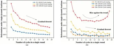
Fig.7.Evolution trend of AS deformation during cyclic loading: (a) 1 MPa edgewise compressive,and (b) QCM.
Through analysis of the experimental results,the occurring times of the two instability damage modes were not only related to the loading but also closely related to the strength of AS itself,and the number of cycles.In this paper,the second type of instability mode appeared in only the loading range of 200-250 kN,which was related to the cycle number for each loading gradient.The test was set to 20 cycles for each loading,which was a relatively small number of cycles.After the tangential modulus of AS was significantly reduced,AS entered a significant plastic deformation phase,in which each cyclic loading will cause damage to the AS,i.e.the CD and asymptotic damage phase.However,due to the small number of cycles set(20),most of the cyclic loading process of AS did not yet reach the second type of damage(deformation continued to go up against the trend) before entering the next cyclic loading.Thus,it was damaged under a sudden increase in dynamic load of 50 kN.Specifically,the AS entered a significant plastic deformation phase.When the number of cycles was small,there was a high probability that the first type of destabilization damage mode occurred,and when the number of cycles was large,there was a high probability that the second type of destabilization damage mode occurred,irrespective of the type of loading.
4.3.Action mechanism of AS under impacts of triaxial dynamicstatic cyclic loading
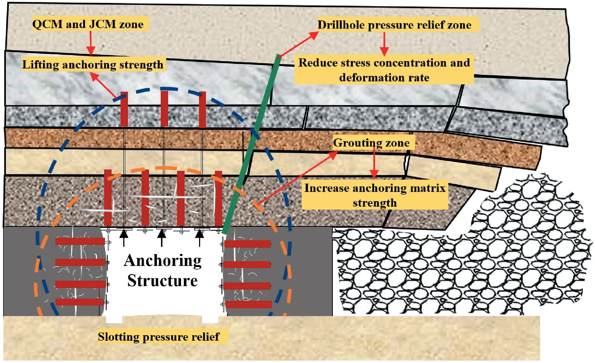
The balance of the original triaxial stress is broken after excavation,with pressure on 5 faces while free on the remaining face of the surrounding rocks.The breakage of the overlying rocks releases energy to the entire roadway frequently.Under the combined action of multiple stresses,the rock mass is in a combined dynamicstatic load.The internal structure of the rock mass remains fairly intact during the initial compression stage.The external load,however,causes the internal stress of the rocks to change and elastic volumetric compression is generated.Nevertheless,as the cracks within the rock mass propagate,expansion occurs on weak planes with a comparatively small structural stiffness,which triggers the distortion and deformation of rock structure.As a result,volume expansion caused by distortion and deformation exerts an extrusion pressure (Fj),possibly described as the normal driving force,on the free face.Due to the constraint of the end faces of the 5 loading surfaces and the crystal lattice linkage effect of the internal rocks,a force resisting the bending and tension(internal forceFn),which is also considered a normal rigidity constraint,emerges in the internal units of the structure.The relative values betweenFjandFnat different locations determines the failure mode at the specific locations.The AS was in a compressive state whenFn>Fjwhile tensile state whenFn The end constraint,which restricted the propagation of cracks,reduced when it was far away from the contact surface,so it was common for larger cracks to release stress in the middle of the free face.Since the major bearing area had transferred to deeper strata,the shallow rock stratum underwent layered fractures,which gradually weakened as they propagated deeper into the structure until a boundary was formed.Only compressive elastic deformation existed on the boundary,with the fractures on both sides resulting in bulging outward.Because no side pressure was observed in the rear of the specimen,apparent tensile spalling took place on both sides of the interface under uniformly distributed dynamic-static loading,which was consistent with the failures of the coal pillar of the roadway along gob in field,as shown in Fig.8a (Li et al.,2022c). When a comparatively large side pressure was applied from the rear,the free face was the area where most of deformation and energy release occurred.Thus,the area within the interface can be almost treated as the pure compression zone,with crack development and propagation from the outside of the boundary to the free face gradually.Eventually,obvious rock spalling occurred on the free face,generating shear slip.This was also consistent with the failures of the coal wall in field. The experimental results of the failures of the BJM specimen were consistent with the findings of Kang et al.(2023),as shown in Fig.8b.The results differed significantly from the overall splitting and detachment characteristics of the rock mass on both sides of the AS under uniaxial compression without side pressure. The interface varied when the stress strength,the support strength,and the rock mass strength changed.As the staticdynamic loading increased gradually,the surrounding rocks witnessed the cracks and started to enter the state of progressive failure whenFj>Fn.With damage accumulation under cyclic loading,the overall rigidity of the structure continued to drop.Therefore,it was necessary to apply active support timely for the roadway surrounding rocks from the outside,which could form an AS.The overall rigidity of the AS was enhanced by providing support resistance to supply additional stress or by improving the surrounding rock properties to reinforce the matrix strength.Consequently,the shear and sliding-resistant strength of the bearing area surpassed the driving force exerted by the sliding of surrounding rocks under cyclic dynamic loading.This approach ensured the stability of the surrounding rocks,providing a safer and more reliable infrastructure.Fig.9 presents the internal damage location diagram of the AS in the experiment.The locations of the damage of the AS under different working conditions were concentrated on the rock mass at a certain depth on one side of the free face. The damage of AS was obtained from the number of internal positioning events and their spatial distribution characteristics(projection ranges on three planes).With the five types of samples as examples,the numbers of events were 355,462,1925,665,and 547.Their spatial distribution ranges were:x(-40-20),y(-50-10),z(-20-30) (see Fig.9a);x(-30-40),y(-50-0),z(-20-0,10-40)(see Fig.9b);x(-40-40),y(-50-10)z(-40-50) (see Fig.9c);x(-40-50),y(-50-20)z(-20-50) (see Fig.9d);x(-40-40),y(-50-10),z(-20-35)(see Fig.9e),respectively.Compared with the structures without anchorage support,the damage of anchored structures were substantially reduced and comparatively small in the sections where anchorage was applied.The damaged zone was either on one side of the bolt,or around the bolt in the shape of a bowl,or symmetrically distributed on both sides of the bolt.In addition,as the loading rate decreased,the damaged area was gradually concentrated as the matrix strength,the anchorage length,and the edgewise compressive strength increased.This trend was particularly apparent in the full-length anchorage specimen.Moreover,the damages were extremely small within a certain range around the anchoring interface when the stress was homogenized (see Fig.9b). Based on this analysis,the support stress compensationFmandFninteracted with each other,andFmincreased as the anchorage length increased.As a result,the damage degree of the AS dropped significantly given a fixed normal driving force.Moreover,the macro-fractures were constrained,and the location of the interface shifted toward the direction of the free face.For this,the overall spallation detachment gave way to concave fractures around the bolt and the tray.As depicted in Fig.8c,both the depth and intensity of the damage were effectively controlled;however,in deep roadways subjected to dynamic loading,stress levels remain high,and impact energy events frequently occur.Owing to the substantial dynamic load strength and rapid strain rate,stress relief is essential.This approach aims to decrease the normal driving forceFjso as to control the internal damage.Furthermore,the bolts need to be installed at a certain angle to control the stability of the roadway in field.Under such condition,the axial support resistance provided consisted of a vertical quantityFmsinα and a horizontal quantityFmcosα,which failed in improving the overall rigidityFn.In the meanwhile,the trays that did not cling closely to the rock surface generated a negative linear force on the surrounding rocks that may result in slip,extrusion and detachment,including Vshaped detachment of the rock surface,as presented in Fig.8d.When the anchorage angle is 90°,the anchoring force can be fully applied to resist the crushing pressure generated inside the structure,so the bearing strength of AS is the highest and the damage degree is the lowest.When the anchorage angle is reduced to 75°,most of the anchorage force can be used to resist the crushing and swelling pressure.However,there is still a small part of the anchorage force parallel to the free surface,so the bearing strength of AS will not be significantly reduced at this time,but the damage degree of the free face increases under the action of parallel anchorage force and cutting.When the anchorage angle is reduced to 60°and 45°,the anchoring force is lost in axial direction,and the anchoring force component in the parallel direction gradually increases.This not only significantly reduces the bearing strength of AS,but also increases the damage degree under the additional shear. In summary,the dynamic-static cyclic loading causedFjto rise gradually,while the cumulative damages causedFnto slowly decrease.Consequently,the interface location shifted toward deeper strata,and rock damage moved deeper.Failures occurred when the critical condition was reached.Therefore,Fjshould be reduced,andFnshould be increased by increasing the matrix and anchorage strength.With this approach,it should be possible to prevent the AS from becoming plastic earlier,thus ensuring the overall stability of the roadway surrounding rocks. Based on the above analysis,the following support measures were proposed to address the challenges of severe deformation of surrounding rocks of deep roadways under frequent dynamic loading and energy release.First,it is crucial to reduce the horizontal stress strength by stress relief in order to minimize the impact energy amplitude and internal driving force,thereby reducing the rate of deformation.Second,for fragmented roadways in surrounding rocks with a low bearing capacity,timely grouting modification needs to be implemented to improve the anchorage matrix strength,so that the bearing capacity of the rock mass can be fully utilized.Third,a full-length anchorage system needs to be adopted to reinforce the rigidity and bearing capacity of the AS.Finally,field construction needs to be carefully carried out to avoid over-inclination of the support bodies upon installation.With the measures,the bearing capacity of the AS under cyclic dynamic loading can be improved effectively for roadways (see Fig.10). Fig.10.Schematic diagram of support control countermeasures. However,the loading range of the primary loading test system was a limitation in our study.Only small ASs were adopted to explore the failure characteristics.Therefore,there was a size effect in the experiment.Both the tension and compression interfaces existed within the anchorage thickness.The conditions where the entire AS was extruded out and the variations of the axial force of the bolt body (Wang et al.,2020) were not considered. In this study,the following conclusions can be made: (1) A triaxial loading test device for AS was designed,ensuring that the stress path in the test is more in line with the engineering field environment. (2) The peak bearing strength of AS is positively correlated to the matrix strength,anchorage length,and compressive strength.The peak bearing strength tends to increase initially and subsequently be stable as the loading rate rises.The bearing capacity decreases significantly when the anchorage direction is highly inclined. (3) The criterion defining the instability of the AS is a negative secant modulus or a persistent increase in deformation against the expected trend.Implementing appropriate strategies to enhance normal stiffness and mitigate the internal driving force can effectively minimize the detrimental effects on the load-bearing capacity of the AS. Declaration of competing interest The authors declare that they have no known competing financial interests or personal relationships that could have appeared to influence the work reported in this paper. Acknowledgments This paper is financially supported by the National Natural Science Foundation of China (Grant Nos.52074263 and 52034007),and the Postgraduate Research and Practice Innovation Program of Jiangsu Province (Grant No.KYCX21_2332).4.4.Supporting countermeasure and experimental limitations
5.Conclusions
杂志排行

Journal of Rock Mechanics and Geotechnical Engineering的其它文章
- Determination of uncertainties of geomechanical parameters of metamorphic rocks using petrographic analyses
- Evaluation of excavation damaged zones (EDZs) in Horonobe Underground Research Laboratory (URL)
- On the calibration of a shear stress criterion for rock joints to represent the full stress-strain profile
- Effect of dynamic loading orientation on fracture properties of surrounding rocks in twin tunnels
- Experimental study on the influences of cutter geometry and material on scraper wear during shield TBM tunnelling in abrasive sandy ground
- Effect of fracture fluid flowback on shale microfractures using CT scanning