Experimental study on workability and permeability of sandy soils conditioned with thickened foam
2024-02-29ZhiyaoFengShuyingWangTongmingQuXiangouZhengFanlinLing
Zhiyao Feng ,Shuying Wang,* ,Tongming Qu ,Xiangou Zheng ,Fanlin Ling
a School of Civil Engineering,Central South University,Changsha,410075,China
b Tunnel and Underground Engineering Research Center,Central South University,Changsha,410075,China
c Department of Civil and Environmental Engineering,The Hong Kong University of Science and Technology,Clearwater Bay,Kowloon,999077,Hong Kong,China
d Geo-Engineering Section,Delft University of Technology,Delft,999025,Netherlands
Keywords:Earth pressure balance (EPB) shield Thickened foam Foam-conditioned sand Permeability Workability
ABSTRACT Water spewing and muck plugging often occur during earth pressure balance (EPB) shield machines tunnelling in water-rich sandy strata,even though the conventional foam has been employed to condition sandy soils.In this study,a novel thickened foaming agent suitable for EPB shield tunnelling in water-rich sandy strata is developed.In contrast to conventional foam-conditioned sands,the thickened foam-conditioned sand has a low permeability due to the consistent filling of soil pores with the thickened foam,and the initial permeability coefficient decreases by approximately two orders of magnitude.It also exhibits a suitable workability,which is attributed to the enhanced capability of the thickened foam to condition sandy soils.In addition,the effect of concentration on the stability of the foam is explained by the Gibbs-Marangoni effect,and conditioning mechanisms for the thickened foam on sands are discussed from the evolution of foam bubbles.
1.Introduction
Earth pressure balance(EPB)shield machines have been widely used to construct various urban tunnels due to their safety and high efficiency(Martinelli et al.,2015;Wang et al.,2023).High-pressure water easily leaks between soil particles and gushes from the outlet of the screw conveyor when EPB shields bore tunnels in water-rich sandy strata(Li et al.,2022).Additionally,the excavated soil easily accumulates in the bottom of the soil chamber,which can be challenging to be discharged (Qu et al.,2019).Water spewing and incomplete muck discharge can strongly affect the efficiency and safety of EPB shield tunnelling.Serious water spewing can lead to excessive settlement in soil strata and even cause ground instability(Zheng et al.,2015).Foam,as one of the most common soil conditioners,is often used to condition the excavated soil in the shield chamber and screw conveyor to ensure that it can be discharged through the screw conveyor in a controlled manner (Zhong et al.,2022).However,the workability of sandy soils is difficult to be improved under water-rich conditions due to the limited capability of conventional foam to condition sandy soils(Wang et al.,2020a),and the permeability coefficient of conventional foam-conditioned sands is often higher than the suggested value,which is 10-5m/s(Hu et al.,2020).
The workability and permeability of muck are two important characteristics that determine whether or not EPB shield machines can safely excavate in water-rich sandy strata.The two features of conditioned sands have received extensive attention.In terms of the workability of foam-conditioned sands,Vinai et al.(2008),Ye et al.(2017),and Wang et al.(2020a) investigated the effects of different conditioning parameters on the workability of foamconditioned sands using slump tests.Their studies show that the slump test can characterize the workability of foam-conditioned sands satisfactorily,and the reasonable slump value of conditioned sands ranging from 15 cm to 20 cm are suggested.In terms of the permeability of foam-conditioned sands,Kim et al.(2019)found that the permeability coefficient of weathered granite soils can be decreased by three orders of magnitude when conditioned with the foam.However,Hu et al.(2020) pointed out that it is difficult to effectively reduce the permeability of sandy soils by purely conditioning with the conventional foam when the water content is higher than 10%.A generally accepted view in the literature is that the permeability coefficient of conditioned soils should be lower than 10-5m/s for at least 90 min to satisfy requirements of EPB shield tunnelling (Borio and Peila,2010;Budach and Thewes,2015).When the conventional foam is insufficient to meet the requirement of low permeability,bentonite slurry and polymer are usually added to assist sand conditioning.Ling et al.(2022)studied the effect of bentonite slurry on the function of foam for changing the permeability characteristics of sands under high hydraulic gradients and pointed out that bentonite particles can stabilize foam bubbles in conditioned sands.Li et al.(2022)investigated the effect of polymers on the performance of the foam and the permeability characteristics of foam-polymer-bentonite slurryconditioned sands.
Foam-conditioned sand is a sand-water-foam mixture,and its workability and permeability characteristics strongly depend on the properties of the foam.Hajialilue-Bonab et al.(2014)found that polymers can increase the viscosity of foaming agents and that the stability of the foam can be significantly enhanced.Petkova et al.(2012) and Bureiko et al.(2015) systematically studied the interaction between surfactants and polymers and the effects of different interacting systems on the foaminess and stability of the foam.Peng et al.(2018) developed a polymeric foaming agent through compositional tests of surfactants,foam stabilizers,and polymers.Some researchers have studied the effects of polymers on the properties of foam and developed polymeric foaming agents.However,the poor conditioning capability of the foam on natural sands under water-rich conditions remains an open challenge.Therefore,there is a need for developing an enhanced foaming agent suitable for EPB shield tunnelling in water-rich sandy strata.
This study is a supplement to the studies by Wang et al.(2020a)and Hu et al.(2020),who reported that sandy soils cannot be effectively conditioned with the conventional foam under waterrich conditions.Aiming at addressing the challenge of sand conditioning with the conventional foam under a high water content,a novel thickened foaming agent suitable for EPB shield tunnelling in water-rich sandy strata was developed through a series of compositional tests based on the thickening properties of alkyl amine oxide.To comprehensively exhibit the features of the proposed novel foaming agent,the foam expansion ratio (FER) and half-life time (th) of the thickened foam of different compositions were tested.Furthermore,slump tests and permeability tests were carried out on thickened foam-conditioned sands.The permeability and workability of thickened foam-conditioned sands and conventional foam-conditioned sands were compared and discussed to show the superiority of sand conditioned with thickened foam.Finally,the mechanism by which the concentration of the foam solution affected the stability of the foam was revealed.The underlying mechanisms supporting the enhancement of the sand conditioning effect were analysed.
2.Testing methods
2.1.Foaming test
2.1.1.Foaming material and system
Through a series of parametric investigations,a thickened foaming agent was obtained by compounding alkyl sulfate (SDS)and alkyl amine oxide (OA-14).The chemical formula and a structural illustration of the two components are listed in Table 1.SDS is an anionic surfactant and a white powder.Its solution shows an excellent foaming ability even under acidic or alkaline conditions.OA-14 is an ampholytic surfactant and a white transparent liquid.It behaves as a cationic surfactant in acidic media and a nonionic surfactant in alkaline media.OA-14 compounded with anionicsurfactants exhibits a good thickening effect.As an example,the major chemical compositions of conventional commercial foaming agents are shown in Table 2.Sodium dodecyl sulfate and dodecyl ammonium chloride are foaming agents,and silicone oil is a foam stabilizer.In contrast with conventional commercial foam,the thickened foam does not require the addition of foam stabilizers.
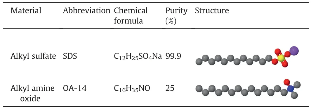
Table 1Information of compounds.

Table 2Chemical compositions of the conventional foaming agent.
The foam generation system follows the requirements of the European Federation for Specialist Construction Chemicals and Concrete Systems (EFNARC,2005).The system consists of an air compressor,a liquid reservoir,a pressure regulating valve,and a foam generator,as shown in Fig.1.The foaming pressure is typically set to 0.3 MPa in sandy strata(Wang et al.,2022).Under the action of compressed air,the foam solution is evenly mixed with air in the foam generator,and the generated foam is collected at the outlet of the measuring plate.The structures of foam under different scales are shown in Fig.2.During the process of EPB tunnelling,the quality of conditioned soils is ensured through the concentration of foaming agent within foaming liquid(CF),the foam expansion ratio(FER),the half-life time (th),and the foam injection ratio (FIR)(Budach and Thewes,2015).The half-life time is defined as the time required for the foam to dissipate to half of its mass.The concentration of foam solution(cf)defines the mass ratio of the surfactant to the foam solution.The relevant parameters can be calculated by

Fig.1.Foam generation system: (a) Experimental configuration,(b) Foam flows in the generator,and (c) Generated foam.

Fig.2.Foam structures at different scales of length.
whereQfis the volume of the foaming agent,QLis the volume of the foaming liquid (foaming agent+water),MSis the mass of the surfactant,MLis the mass of the foam solution(surfactant+water),QFis the volume of foam,andQSis the volume of the soil specimen.
2.1.2.Foaming procedures
The procedure for compositional tests of the thickened foam is as follows.
(1) According to the designed mass ratio and concentration of the foam solution(cf),as shown in Table 3,a certain amount of alkyl sulfate (SDS) and alkyl amine oxide (OA-14) was poured into a beaker containing a certain amount of water.The mixture was stirred for 5 min at a low speed(500 r/min)to avoid generating foam bubbles during the stirring process.The surfactant was fully dissolved in the water.The test temperature is 25°C.The mixer used in this study is a thermostatic magnetic mixer,as shown in Fig.3.

Fig.3.Thermostatic magnetic mixer.

Table 3Compositions of the thickened foam.
(2) The prepared foam solution was slowly poured into the reservoir,and the valve of the liquid inlet was closed.Then,the air compressor was initiated,and the foaming pressure was set to 0.3 MPa.The generated foam was collected at the outlet of the measuring plate.
(3) The half-life time (th) of the thickened foam of different compositions was measured under standard atmosphericpressure.The half-life time testing device is shown in Fig.4.First,the foam cylinder was filled with foam,and the initial mass of foamMFwas measured.Then,the mass of the dripping foam solution and the elapsed time were recorded.When the mass of the drops reachesMF/2,the elapsed time is termedth.

Fig.4.Half-life time testing device.
(4) The volume of the foamQFand the volume of the foam solutionQLafter foam burst were measured using a graduated cylinder under the standard atmospheric pressure,and theFERof the thickened foam of different compositions was calculated according to Eq.(3).
2.2.Laboratory tests of the thickened foam-conditioned sand
2.2.1.Testing materials
The sandy soil used in the study was collected from the Xiangjiang River,Changsha,China.The sandy soil was sieved,and then a soil specimen with the grain size distributions shown in Fig.5 was prepared,which is the same as that studied by Hu et al.(2020)and Wang et al.(2020a).The silt and clay particles (both smaller than 0.075 mm in diameter) comprises only 0.08% of the total,and the sand and gravel particles(both larger than 0.075 mm in diameter)comprises 67.87%and 32.05%,respectively.The specific gravity and minimum dry density of the specimen are 2.63 and 1.74 g/cm3,respectively.The maximum porosity of the dry sand is 0.34,and the porosity of the foam-conditioned sand is 0.48.Besides,its coefficients of uniformity (Cu) and curvature (Cc) are 9.85 and 0.39,respectively.According to ASTM D2488-17e1 (2017),the soil is classified as a poorly graded sand (SP).
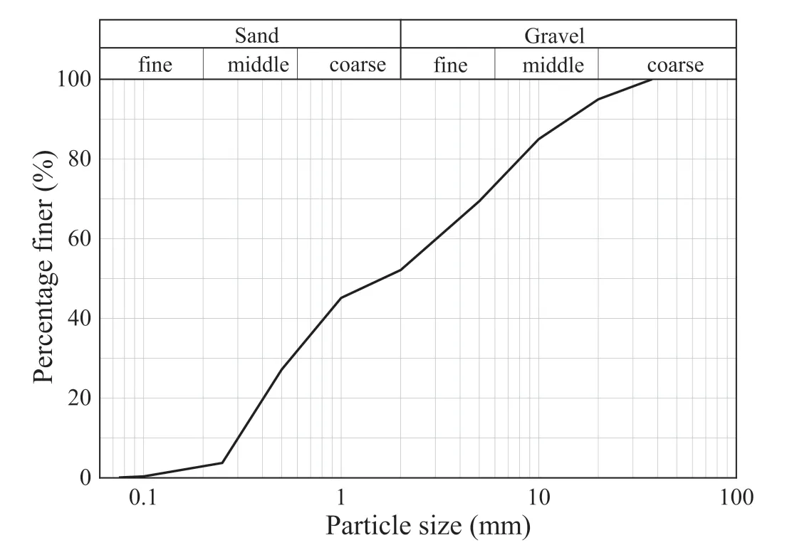
Fig.5.Grain size distribution of the soil specimen.
2.2.2.Testing approaches
Slump tests are frequently performed to evaluate the workability of conditioned sands during EPB shield tunnelling.These tests were performed following the ASTM C143/C143M-20 (2020)standard.First,the mixed foam-conditioned sand was poured into a standard slump cone layer by layer (six layers).Then,the slump cone was lifted vertically,and the overall lifting time was approximately 5 s.The slump height of the specimen was recorded to analyse the workability of foam-conditioned sands.If a slump specimen was tilted,and a repeat test was conducted.The conditioning parameters of the sandy soil for the slump tests are listed in Table 4.

Table 4Slump test conditions.
Constant head permeability tests were carried out on foamconditioned sands by a self-designed,large-scale permeameter.It consists of a tempered glass cylinder,a top cap,a bottom plate,a top porous disk,and a bottom porous disk,as shown in Fig.6a.The diameter and height of the permeameter are 30 cm and 75 cm,respectively.The water pressures above and below the soil specimen are measured by the pressure gauge in the permeability tests.The height difference between two pressure gauges is 60 cm,and the distance between the bottom gauge and the bottom porous disk is 2 cm,as shown in Fig.6b.The target water head is achieved by adjusting the height of the water tank(by placing the water tank on different floors of the building).More details can be referred to Hu et al.(2020).The testing conditions of the permeability tests are listed in Table 5.Following the ASTM D2434-19(2019)standard,the main procedures of the permeability test are described as follows:

Fig.6.Large-scale permeameter: (a) Picture of the permeameter,and (b) Schematic diagram of the permeameter.

Table 5Testing conditions for the permeability tests.
(1) The weighed water and dried sand were poured into a mixer according to the designed water content.The mixer was rotated clockwise for 1.5 min and then anticlockwise for 1.5 min.Then,the wetted sand was left overnight to ensure that it could fully absorb the water.Subsequently,the wetted sand was stirred with foam for 1 min,and the foam was perfectly homogenized with the sand.
(2) A filter paper with a diameter of 30 cm was placed on the lower porous disk before filling the soil specimen.Then,the fresh foam-conditioned sand was quickly placed into the permeameter layer by layer,and the filling height was approximately 60 cm.
(3) The top cap was tightly installed to ensure no air leakage during the permeability test.The required constant water head was provided by placing the water tank at a designated level.Tap water was slowly supplied to the top of the specimen,and the air release valve was opened until the permeameter was filled with water.
(4) A one-dimensional downwards permeability test was initiated when the air release valve was closed,and the start time of the permeability test was recorded.The preparation process for the permeability test took approximately 25 min for each test.
(5) The height of the soil specimen(h),the water pressure(Pu)at the top of the specimen (monitored by the top gauge in Fig.6),and the water pressure (Pd) at the bottom of the specimen (monitored by the bottom gauge in Fig.6) were recorded at the permeation time(t).The flow quantity(Q)at the permeation time (t) was determined and recorded by collecting the volume of water flowing out of the specimen over a short period of Δt.The permeability coefficient(k)was calculated by Darcy’s law,as reported in Hu et al.(2020).When the permeability coefficient became nearly constantover time,the permeability test was terminated(Wang et al.,2021).
The initial hydraulic gradients for the permeability tests are designed based on the Longquan water tunnel in Kunming,China.This tunnel is constructed by an EPB shield machine with an excavation diameter of 6.44 m.The maximum hydrostatic pressure head reaches more than 50 m(the maximum burial depth is 75 m),and the maximum hydraulic gradient reaches 10.3.The maximum hydraulic gradient is designed to be as high as 17 in permeability tests,and this high value currently is uncommon for EPB shield tunnelling in engineering practice.However,this value is likely to emerge given the rapid development of EPB shield tunnelling technologies.
3.Experimental results and analysis
3.1.Results of compositional tests
3.1.1.Foam stability
Foam bubbles have large interfacial free energies and are thermodynamically unstable,and the bursting of foam bubbles is inevitable.The stability of the foam was analysed using a onedimensional downwards drainage experiment.The drainage ratio is defined as the ratio of the weight reduction of the foam solution to the total weight of the foam solution,expressed as a percentage(Zhao et al.,2021).The lower the drainage ratio at a given time is,the greater the stability of the foam is.Fig.7 shows the evolution of the drainage ratio of the thickened foam at different compositions.Three stages of the thickened foam decay are observed: a slow decay stage,a sharp decay stage,and a gradual slowing stage.The stability of the foam is relatively poor when the mass ratio of SDS to OA-14 is 4:3 or 4:4 atcf=2‰,and no slow decay stage is observed for the thickened foam.The slow decay stage is either short or nonexistent for the conventional foam.In addition,the half-life time can be obtained through the intersection of red dashed line and drainage ratio curve.For example,this 35.67 min when the mass ratio of SDS to OA-14 is 4:1 atcf=3‰.

Fig.7.Evolution of drainage ratios.
The foam solution drips rapidly from the bottom of the half-life time testing device after the foam is generated(Selmi et al.,2020).Fig.8a shows that multiple streams of a thick,slimy foam solution slowly drip from the bottom of the half-life time testing device during the sharp decay stage for the thickened foam,while Fig.8b shows that a stream of a foam solution similar to water rapidly drips from the bottom of the half-life time testing device during the sharp decay stage for the conventional foam.The foam bubbles are spherical and separated by a thick liquid film when the freshly thickened foam is poured into the half-life time testing device.The foam bubbles are relatively uniform in size.The diameter of foam bubbles in the upper part of the half-life time testing device increases,and the liquid film of the foam becomes thinner with time.Finally,the foam bubbles adhere to each other and formed polyhedrons.The closer the foam to the top of the half-life time testing device,the larger the diameter of the foam bubbles,and the thinner the liquid film,as shown in Fig.9.The reason is that the foam solution flows down along intricate plateau channels due to the foam drainage governed by gravity and surface tension.The increase in the size of the foam bubbles is attributed to the coarsening and coalescence of the foam (Magrabi et al.,1999;Fameau and Salonen,2014).

Fig.8.Drainage photos of the foam: (a) Thickened foam,and (b) Conventional foam.
The half-life time,a simple and universally accepted index to assess foam stability,has been widely adopted (Sebastiani et al.,2019).Fig.10 shows the variation in the half-life time versus the concentration of the foam solution at different mass ratios.The right figure is an extended image of the foam solutions consisting of OA-14 alone and SDS alone.The half-life time first increases and then decreases as the concentration of foam solutions increases,except for the foam with OA-14 alone.Similar observations are obtained as the mass ratio of SDS to OA-14 increases.The half-life time is the longest and reaches 201 min when the mass ratio of SDS to OA-14 is 4:2 atcf=3‰.The foam stability affects the workability and permeability of the conditioned sand,and determines the stability of the mechanical properties of the conditioned sand.Therefore,the thickened foam withth=201 min is used for the following tests.
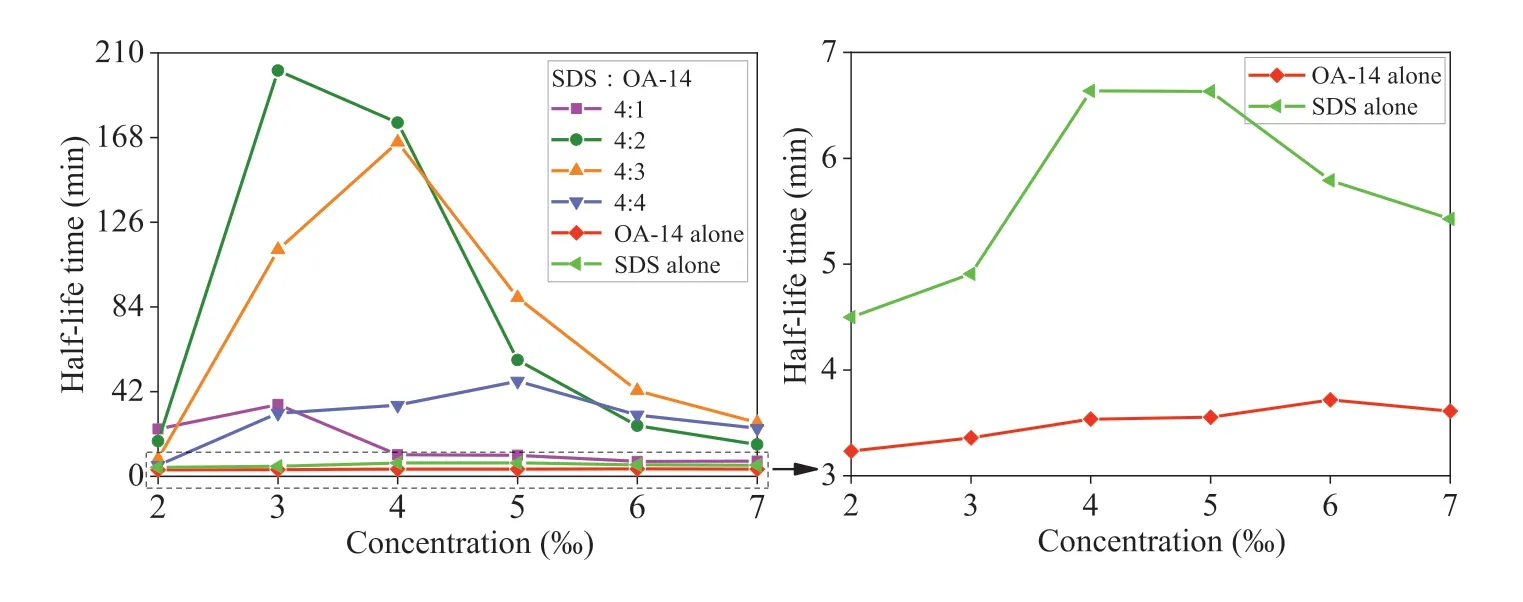
Fig.10.Variation in the half-life time versus the concentration of the foam solution.
3.1.2.Foaming ability
The foaming ability during the foam generation stage can be reflected byFER.Fig.11 shows theFERvalues of the thickened foam with different concentrations and mass ratios of SDS to OA-14.TheFERof the thickened foam gradually increases as the concentration of the foam solution increases.This phenomenon can be explained by the adsorption rate of surfactant molecules on the gas-liquid interface (Wang et al.,2016).When the concentration of the foam solution increases,more surfactant molecules are rapidly adsorbed to the gas-liquid interface during the foam generation stage.The foaming ability is determined by the number of surfactant molecules adsorbed on the gas-liquid interface.When SDS is solely used for foaming agent,the foaming ability of the foam is better than that of other foam under the same concentration,which further verifies that SDS has an excellent foaming ability.This is also the reason why most foam products choose SDS as the main foaming agent.TheFERof the thickened foam gradually increases with the mass ratio of SDS to OA-14.The reason is that the mass of the main foaming agent,SDS,increases for the same concentration of the foam solution as the mass ratio of SDS to OA-14 increases.Based on practical engineering experience,Yan et al.(2010) proposed that the foam meets the construction requirements of EPB shield machines whenFERis in the range of 10-20.TheFERis approximately 11 for the thickened foam when the mass ratio of SDS to OA-14 is 4:2 atcf=3‰,which is also adopted in the following study.

Fig.11.Variation in the FER versus the concentration of the foam solution.
3.2.Comparison of the workability of thickened and conventional foam-conditioned sands
3.2.1.Slump value
Fig.12 shows the results of the slump tests.Note that the conventional foam withFER=10 andth=6 min was used by Wang et al.(2020a).Whenw=5%,the slump values of thickened and conventional foam-conditioned sands first decrease and then increase asFIRincreases.This observation agrees with the result obtained by Wang et al.(2020a).The sandy soil without foam is non-cohesive.When a small amount of foam is added,the surface of dry sand particles is wetted by the water in the foam.The water film on the surface of sand particles enhances the soil cohesion so that the slump value decreases with an increase inFIR.The yield strength of the foam-conditioned sand decreases when more foam is injected,further leading to an increase in the fluidity and slump value of the foam-conditioned sand (Wang et al.,2020a).Whenw=10%,the slump values of thickened foam-conditioned sands increase withFIR,and the slump values of conventional foamconditioned sands first increase and then remain stable as theFIRincreases.The workability of conventional foam-conditioned sands is too strong whenw=10%andFIRis more than 15%,and the slump values far exceed the ideal range of 15-20 cm.The conditioned sand with a high flow ability is extracted uncontrollably through the screw conveyor,and some gravels may be accumulated in the bottom of the soil chamber(Vinai et al.,2008).The slump values of thickened foam-conditioned sands are significantly lower than those of conventional foam-conditioned sands.For example,with a constantw=10% andFIR=20%,the slump values are 19.7 and 25.6 cm,respectively,demonstrating that thickened foamconditioned sands have a relatively strong plasticity compared with conventional foam-conditioned sands.The thickened foam stably fills in the pores of the sandy soil because it has a stronger capability to combine with sandy soil compared with the conventional foam,promoting the water retention and cohesion of the thickened foam-conditioned sand.
3.2.2.Rheological state
The rheological state of foam-conditioned sands in slump tests is also an important feature for evaluating the workability of soil conditioning (Peila et al.,2009).According to Wang et al.(2020a),conventional foam-conditioned sands can be classified into 5 categories: insufficient,suitable without any water or foam bleeding,suitable but with water bleeding,excessive with likely foam bleeding,and excessive with water bleeding.Table 6 shows the rheological states of thickened and conventional foamconditioned sands under differentFIRvalues withw=10%.WhenFIRis higher than 20%,water and foam immediately bleed once the slump cone has been lifted.For the thickened foam-conditioned sand,no water or foam bleeding is observed for all conditioning conditions.The comparison between the rheological states of thickened and conventional foam-conditioned sands shows that the thickened foam has a stronger water retention capacity.The reason is that the thickened foam has a stronger capability to combine with sandy soil compared with the conventional foam.Therefore,the thickened foam can consistently remain inside the pores of the sandy soil,and the water inside the sandy soil cannot flow out due to the blocking effect of foam bubbles.These rheological states of thickened foam-conditioned sands allow them to be discharged through the screw conveyor in a controlled manner during EPB shield tunnelling.

Table 6Comparative rheological states of thickened and conventional foam-conditioned sands.
3.3.Comparison of the permeability of thickened and conventional foam-conditioned sands
Fig.13 shows the variation in the permeability coefficient (k)versus time for the thickened foam-conditioned sand withw=10%andFIR=20%.Similar to conventional foam-conditioned sands(Huang et al.,2019),the time-varying curves of the permeability coefficients for thickened foam-conditioned sands generally exhibits four main periods,including a short-term reduction period,an initial stable period,a fast growth period,and a slow growth period.The average value of the permeability coefficient during the initial stable period is defined as the initial permeability coefficient.The permeability coefficient shows a short-term reduction during the early stage of the permeability test,which can be attributed to the gas bubbles and fine soil grains constantly adjusting their positions in the soil skeleton to form a more effective water-blocking structure.

Fig.13.Results of the permeability tests with different water heads.
As shown in Fig.14,when the water head(H)is 2.9 m,5.6 m and 9.6 m,the initial permeability coefficients of the thickened foamconditioned sand are 3.45 × 10⁻⁷m/s,7.32 × 10-7m/s and 1.15 × 10⁻⁶m/s,respectively.The initial duration of the stable period under different water heads is more than 350 min.The initial permeability coefficient of thickened foam-conditioned sands increases with the water head,while the initial duration of the stable period is less affected by water heads.The sand pores are durably filled with foam bubbles due to the high capability of the thickened foam to combine with the sandy soil.Therefore,the sandy soil can be conditioned with the thickened foam even at a high water content (w=10%),satisfying the permeability requirements for EPB shield tunnelling (i.e.the permeability coefficient is lower than 10-5m/s,and maintains for at least 90 min).

Fig.14.Expanded inset of the early stage of the permeability coefficient.
Fig.15 shows a comparison of the time-varying curves of the permeability coefficients of two foam-conditioned sands.Note that the conventional foam withFER=10 andth=6 min was used by Hu et al.(2020).In addition,the permeability coefficient ofunconditioned sand is also shown in Fig.15,with its value being 4 × 10⁻⁴m/s.No short-term reduction period or initial stable period is observed for conventional foam-conditioned sands.All initial permeability coefficients far exceed the upper limit of 10-5m/s.The growth rates of the permeability coefficients are high during the rapid growth stage.This can be attributed to the fact that conventional foam bubbles dissipate and flow out easily.Furthermore,under the same conditioning parameter(w=10%,FIR=20%),the initial stable period is longer for the thickened foamconditioned sand.Compared with the conventional foamconditioned sand,the initial permeability coefficient decreases by approximately two orders of magnitude,and the permeability coefficient increases slowly during the rapid growth stage.The reason is that thickened foam bubbles remain in the pores of the sandy soil for a long time due to the stronger capability of the thickened foam to combine with the sandy soil.The seepage channels inside the sandy soil are effectively blocked by the thickened foam bubbles.Additionally,the thickened foam has a better stability,and the water-plugging structure formed by foam bubbles and sand particles is more stable.Therefore,the thickened foam-conditioned sand maintains a low permeability for a longer time.

Fig.15.Permeability coefficients comparison between thickened and conventional foam-conditioned sands.
4.Discussion
4.1.Effect of concentration on the stability of the foam
The stability of foam bubbles first increases and then decreases as the concentration of the foam solution increases.This phenomenon can be explained by the Gibbs-Marangoni effect (Sett et al.,2014;Vitasari et al.,2020).When a liquid filmAthins,the surface tension on the liquid filmAtransitorily increases because the surfactant molecules adsorbing on the surface of the liquid film becomes sparse.As shown in Fig.16,when the concentration of the foam solution is below the critical micelle concentration (CMC),surfactant molecules adsorbing on the surface of liquid filmBmigrate to the surface of liquid filmAn under the action of the surface tension difference.Surfactant molecules carry nearby liquid from the surface of liquid filmBto the surface of liquid filmAduring the migration process,leading to the recovery of the thickness of liquid filmA.However,when the concentration of the foam solution is above the critical micelle concentration (CMC),surfactant molecules on the surface of liquid filmAare mainly replenished by migrating from the inside of the solution.The concentration of surfactant molecules on the surface of liquid filmAcan also be recovered,but the thickness of liquid filmAcannot because no surfactant molecules migrate on the surface of the liquid film,and no liquid is carried to liquid filmA.Thus,the stability of the foam is poor,and the thickness of liquid filmAcannot be recovered.
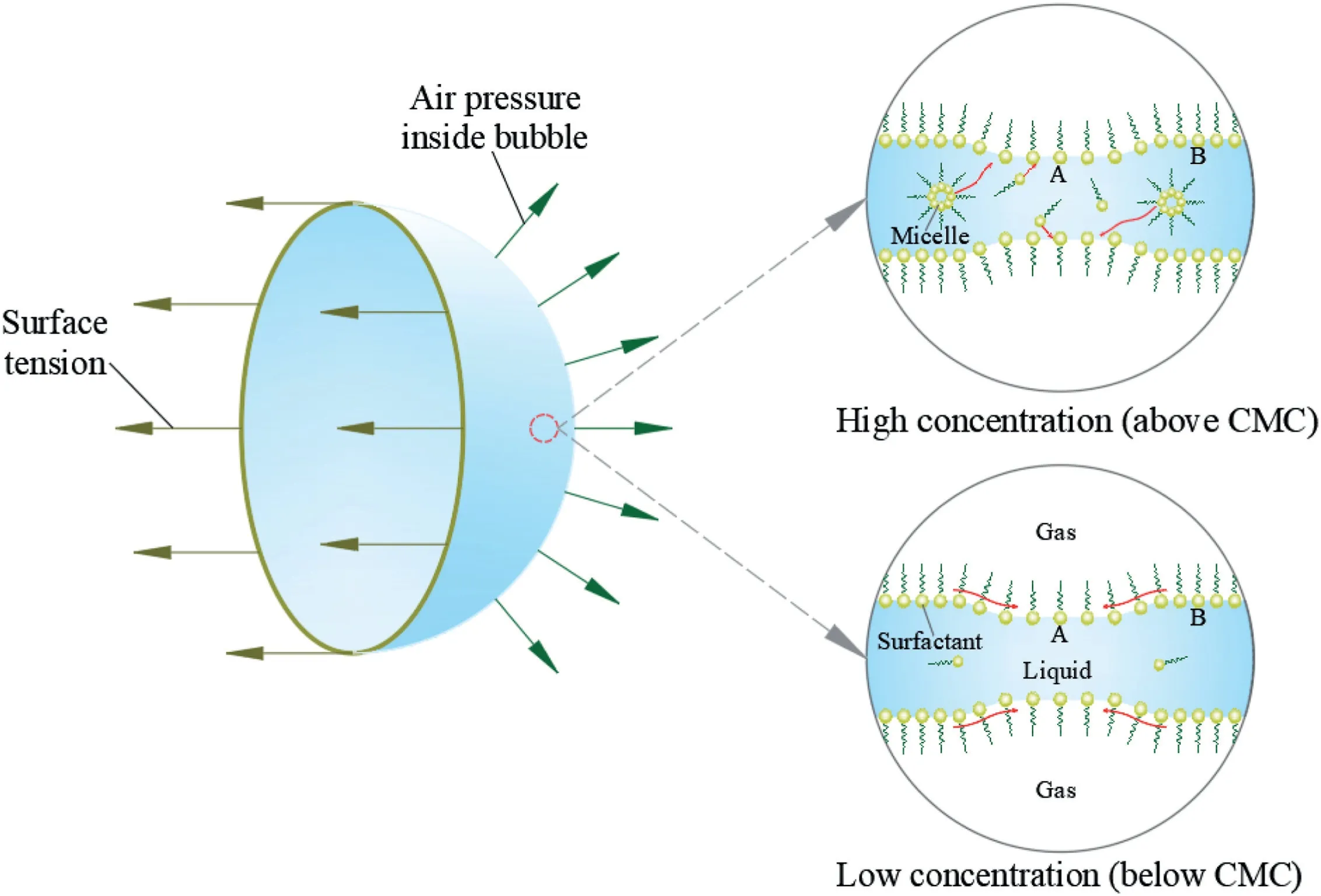
Fig.16.Schematic diagram of the self-healing of the liquid film.
The essence of the Gibbs-Marangoni effect is the elasticity of the liquid film,which can be expressed by
whereEis the elasticity of the liquid film,sis the area of the liquid film,and γ is the surface tension.Eq.(5)shows that a larger dγ/dsgive rise to a greater elasticity of the liquid film.dγ/ dsis equal to 0 for a pure liquid,indicating that the surface tension does not change with the variation in the area of the liquid film and that the liquid film has no elasticity.Therefore,the foam bubbles with a low dγ/dsvalue is unstable due to a lack of self-healing.
The adsorption speed from the solution to the surface of the liquid film is related to the concentration of the surfactant solution.A low concentration of the surfactant solution results in a low density of the surfactant molecules on the surface of the liquid film.The difference in the surface tension is small when the liquid film deforms,i.e.the value of dγ/dsis low.In this case,the self-healing ability of the liquid film is poor because the liquid film has a low elasticity,leading to a poor stability.Otherwise,when the concentration of the surfactant solution is too high,the concentration of surfactant molecules on the surface of the thinned liquid film is mainly replenished from the inside of the solution to reach a new equilibrium state.The stability of the foam is also poor,as the thickness of the liquid film cannot be recovered.Therefore,the concentration of the foam solution is not as high as possible for EPB shield tunnelling in engineering practice.Commonly,it is slightly lower than the critical micelle concentration.
4.2.Conditioning mechanism for thickened foam on sands
Foam bubbles are typically smaller than the pore sizes of conditioned sands,and some foam bubbles can migrate or separate from conditioned sands with the replaced water due to buoyancy(Wu et al.,2020).This process occurs immediately after the wetted sand is mixed with foam.This is why water or foam bleeding phenomena are observed when the sandy soil is conditioned with conventional foam under a high water content.The viscosity of the thickened foam solution increases due to the thickening effect of OA-14.The thickened foam is consistently trapped in the pores of the sandy soil because it has a stronger capability to combine with sandy soil compared with the conventional foam.Furthermore,the pore water is sealed inside the sandy soil.Thus,the conditioned sand has a suitable workability,and no water or foam bleeding is observed in the slump tests.To further verify the excellent capability of thickened foam to combine with sandy soil,the slump test was carried out on the sand withw=15%andFIR=50%.As shown in Fig.17,although the clear water bleeds from the periphery of the sand specimen,no foam bleeding is observed in the slump tests even under highwandFIR.
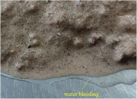
Fig.17.Periphery of the sand specimen with w=15% and FIR=50%.
The permeability of foam-conditioned sands is closely related to the water-plugging capability of foam bubbles to soil pores.As shown in Fig.18,it is significantly affected by the stability,quantity,size of foam bubbles,and the contact state between foam bubbles and soil skeleton(Wang et al.,2020b).The stability of foam bubbles in the mixture is greater than that of foam bubbles in air because solid particles create a steric barrier (Hunter et al.,2008),such as the bubble a and bubble b.The evolution of the behavior of foam mixed with soil can be analysed using the same theory for the pure foam(Selmi et al.,2020),for example,the evolution process occurs among the bubble a and bubble c-g.The foam is destabilised by three mechanisms: drainage,coalescence,and coarsening.Generally,those three mechanisms occur interdependently and can accelerate each other (Magrabi et al.,1999;Fameau and Salonen,2014).
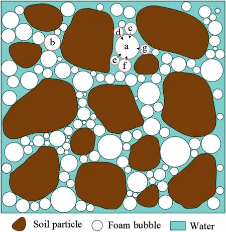
Fig.18.Simplified model of the sand conditioned with foam.
The thickness and strength of liquid film are the two most important factors that affect the stability of foam bubbles.The thickness of the liquid film is mainly governed by the drainage speed.A low surface tension and a high viscosity of foam solution are conducive to retarding the drainage process (Safouane et al.,2001).The viscosity and surface tension of two foam solutions are shown in Fig.19.It can be concluded that the thickness of liquid film of thickened foam is thicker than that of conventional foam.The strength of the liquid film is closely related to the surface viscosity,which depends on the orientational density of surfactant molecules (Exerowa and Kruglyakov,1997).According to Li et al.(2022),mixtures of anionic and nonionic surfactants have a higher orientational density.Alkyl sulfate (SDS) is an anionic surfactant.Alkyl amine oxide(OA-14)is an ampholytic surfactant,and it behaves as a nonionic surfactant in alkaline media(the pH value of thickened foam solution is 8).Hence,the thickened foam is relatively stable due to a high strength of the liquid film.Simultaneously,the high surface viscosity is more conducive to mixing and contacting the soil (Ali et al.,2020).Therefore,the duration of the initial stable period of thickened foam-conditioned sands is longer than that of conventional foam-conditioned sands.

Fig.19.Comparison of two foam solutions: (a) Viscosity,and (b) Surface tension.
The size and quantity of foam bubbles are significantly affected by coarsening and coalescence.As shown in Fig.20.Coarsening is defined as the evolution of gas diffusing from smaller gas bubbles to larger ones due to a pressure difference (Khakalo et al.,2018).Coalescence occurs when thin films between adjacent foam bubbles rupture and a single large bubble is formed(Forel et al.,2019).The coarsening process of foam bubbles is slow when the liquid film is relatively thick.According to Laplace equation,the gas diffusion from the small bubble to the large bubble also slows down when the surface tension decreases.In addtion,it is difficult for the gas to pass through the liquid film of thickened foam because the surfactant molecules are arranged more closely.On the other hand,the coalescence process of foam bubbles retards as the strength of the liquid film increases.More foam bubbles exist in the pores of conditioned soil,and the size of foam bubbles is smaller.Therefore,the thickened foam can significantly reduce the permeability coefficient of conditioned soil.

Fig.20.Schematic diagram of the two instability mechanisms.
5.Conclusions
Based on the thickening effect of OA-14,a series of compositional tests is conducted to develop a thickened foaming agent suitable for water-rich sandy strata.TheFERand half-life time of the thickened foam under different conditions are measured.Furthermore,the slump tests and permeability tests are carried out on thickened foam-conditioned sands,and their workability and permeability are analysed and compared with those of conventional foam-conditioned sands.The following conclusions can be drawn:
(1) The decay of thickened foam includes three stages: a slow decay stage,a sharp decay stage,and a gradual slowing stage.The half-life time of the thickened foam first increases and then decreases as the concentration and mass ratio of SDS to OA-14 increase,andFERof the thickened foam gradually increases.
(2) Whenw=5%,the slump value of thickened foamconditioned sands first decreases and then increases asFIRincreases.Whenw=10%,the slump value of thickened foam-conditioned sands increases withFIR.Compared with the conventional foam,the thickened foam has a stronger capability to combine with sandy soils.No foam bleeding is observed even under a high water content.
(3) Under the same conditioning condition(w=10%,FIR=20%),the thickened foam-conditioned sand has a longer initial stable period that reaches 350 min.The initial permeability coefficient decreases by approximately two orders of magnitude compared with that of conventional foamconditioned sands.
(4) A high concentration is not conducive to the stability of the foam due to the poor self-healing ability of the liquid film.The viscosity of the thickened foam is higher than that of the conventional foam,effectively promoting the workability of the muck.Meanwhile,foam bubbles are consistently trapped in the pores of the sand,and the process of drainage,coarsening,and coalescence is slow for the thickened foam.Thus,a strong water-plugging capability can be maintained for a long period.
Further studies are planned to investigate the intrinsic chemistry and microscopic mechanism of the thickening effect to further optimise the performance of the thickened foam.
Declaration of competing interest
The authors declare that they have no known competing financial interests or personal relationships that could have appeared to influence the work reported in this paper.
Acknowledgments
The financial support from the National Natural Science Foundation of China (Grant No.52022112) and the Fundamental Research Funds for the Central South University (Grant No.2023ZZTS0366) are acknowledged and appreciated.The authors are also grateful for the help from Dr.Ji Zhao of China University of Mining and Technology.
杂志排行

Journal of Rock Mechanics and Geotechnical Engineering的其它文章
- Determination of uncertainties of geomechanical parameters of metamorphic rocks using petrographic analyses
- Evaluation of excavation damaged zones (EDZs) in Horonobe Underground Research Laboratory (URL)
- On the calibration of a shear stress criterion for rock joints to represent the full stress-strain profile
- Effect of dynamic loading orientation on fracture properties of surrounding rocks in twin tunnels
- Experimental study on the influences of cutter geometry and material on scraper wear during shield TBM tunnelling in abrasive sandy ground
- Effect of fracture fluid flowback on shale microfractures using CT scanning