Numerical modelling of post-failure behaviors of coal specimens
2024-02-29AjeetYadavBhaskaraBeheraGauriShankarPrasadSinghSanjayKumarSharma
Ajeet Yadav,Bhaskara Behera,Gauri Shankar Prasad Singh,Sanjay Kumar Sharma
Department of Mining Engineering,Indian Institute of Technology (Banaras Hindu University) Varanasi,Uttar Pradesh,221005,India
Keywords:Strain softening Dilatancy Interface Shape effect Residual strength
ABSTRACT A modelling approach consisting of best-fit relations to estimate the post-yield strength parameters is presented for simulating post-peak behavior beyond the point of residual strength of coal pillars having different w/h ratios.The model was developed based on back-analysis of the complete stress-strain behavior of specimens belonging to six different Indian coal seams with different w/h ratios of 0.5-13.5.It was found that the simultaneous degradation of the cohesion and friction angle of the Mohr-Coulomb rock material characterizes the post-peak strength behavior of the rock.The resulting expressions are simplistic as they require parameters that can be easily determined using uniaxial and triaxial compression results.Eventually,the developed model was validated by simulating the triaxial tests of coal specimens with different sizes under varying confining stresses and comparing its findings with the published test results.The study showed that its implementation in the numerical model could reproduce laboratory-observed mechanical response,deformation behavior,and failure mechanism very closely.
1.Introduction
With technological advances and dwindling shallow-tomoderate depth coal reserves,there is an increasing need to build large underground workings at large overburden depths and in challenging geo-mechanical conditions(Peng et al.,2017).In these conditions,the safe and optimal design of coal mining structures depends not only on the peak strength but also the nonlinear postfailure behavior(Tutluo˘glu et al.,2015).In particular,it is crucial to characterize residual strength to optimally design yielding chain pillars in deep longwall workings prone to rockbursts(Haramy and Kneisley,1990;Yavuz and Fowell,2001;Badr et al.,2002).Furthermore,understanding the post-peak strength is essential for optimal design of abutment chain pillars.These pillars must remain stable until they are part of an active longwall working and undergo a gradual failure to produce a smooth subsidence profile upon extracting both adjacent panels (Yadav,2022).Poor assessment of post-failure and peak strength can result in an irrational design of the pillars,causing either functional or structural failure (Salamon and Munro,1967;Galvin et al.,1999;Merwe,2003;Li et al.,2015)or loss of valuable coal resources(Yu et al.,2016;Zhang et al.,2017).
Most empirical designs are based on a limited database and cannot be used beyond their limits(Sheorey,1993;Das et al.,2019).Conversely,analytical methods grossly oversimplify the typically complex geo-mechanical systems (Sinha and Walton,2019a).As a result,the increasing reliance on numerical modelling has proven its significant role in the design and stability analysis of mining structures(Alejano and Alonso,2005).The growing computational capabilities and improved understanding of rock mechanics have strengthened its position as a reliable tool.
Despite its inability to explicitly capture the stress-induced fracturing at the micro-scale,the continuum method has been a preferred choice for numerical modelling of geomechanical problems at different scales (Singh and Singh,2011;Singh et al.,2011;Feng et al.,2019;Behera et al.,2020;Yadav et al.,2020a).Conversely,the application of discontinuum methods has primarily been limited to the investigation of the damage process in laboratory-scale models (Kazerani and Zhao,2010;Ghazvinian et al.,2014;Li et al.,2017,2019;Mayer and Stead,2017).It requires a large memory size and input properties owing to discretization at the grain and sub-grain levels (Sinha and Walton,2020).The continuum method,on the other hand,regards the ground as an equivalent continuous material with characteristics that roughly incorporate the impact of joints and discontinuities(Fairhurst and Pei,1990).Successful implementation of this method has proven its worthiness for investigating the macroscopic rock behavior under varying geo-mining conditions (Yasitli and Unver,2005;Singh and Singh,2009;Wang et al.,2011,2013;Jiang et al.,2012;Suchowerska Iwanec et al.,2016;Yadav et al.,2020b).
Appropriate constitutive laws for stress-strain behavior are necessary to accurately analyze stress and deformation in criticalstate structural problems using continuum methods (Sinha and Walton,2018).The input of related parameters for elastic and post-failure states is essential for enhancing the quality of results(Tutluo˘glu et al.,2015).Numerical modeling programs commonly provide options for yield function for peak failure or yield analyses.However,parameters related to the constitutive laws of plasticity and strain softening are required to model stress and deformation in the post-failure state.For example,fast Lagrangian analysis of continuum (FLAC) requires functional forms for the decay of cohesion,friction angle,and dilation angle in case of Mohr-Coulomb constitutive model.Unfortunately,the suggestions for obtaining those functions for post-failure variations of cohesion,friction angle,and dilation angle of rocks are scarce (Pourhosseini and Shabanimashcool,2014).
A few attempts have been made to estimate the post-failure parameters using servo-controlled stiff-loading machines in the laboratory.Based on the data mining of laboratory test results of sandstone and mudstone,Pourhosseini and Shabanimashcool(2014) proposed hyperbolic functions to estimate the post-failure variation of cohesion and dilation angle of the Mohr-Coulomb yield envelope with the plastic shear strain.Lin et al.(2018) proposed a linear variation of Hoek-Brown strength parameters with plastic shear strain for sandstone rock.They further reported a quadratic relation between these parameters and the confining stress.Based on the damaged controlled laboratory tests,Renani and Martin (2018) proposed an exponential relation for cohesion degradation and friction mobilization with plastic shear strain for the brittle failure of rocks.Several other researchers have used the strength degradation index (Fang and Harrison,2001;Yuan and Harrison,2004) and damage-based models (Wang et al.,2017;Cai et al.,2018;Ren et al.,2021) to simulate the post-failure stressstrain behavior.
Building on Detournay(1986)work,Alejano and Alonso(2005)analyzed laboratory results of different rocks to propose a dilation model considering the confining stress and inelastic strain.They also proposed a relation for estimating peak dilation angle as a function of confining stress and exponential function for the decay of the peak dilation angle with plastic shear strain.Zhao and Cai(2010) noted that this model did not apply to crystalline rocks and proposed a nine-parameter model for mobilization of dilation angle with inelastic strain and confining stress.Several models(Pourhosseini and Shabanimashcool,2014;Walton and Diederichs,2015a;Zhao and Li,2022) have been proposed after that for this purpose.While these models vary in complexity regarding the number of input parameters,they consider the same constitutive parameters for the dilation angle.
Other methods for estimation of the post-failure parameters include back-analysis of field and laboratory observed mechanical behaviors.This includes peak strength,post-peak deformation slope,failure pattern,rock bolt loading and deformation behavior,and entries and coal ribs convergence based on trial-and-error technique (Mohan et al.,2001;Badr et al.,2002;Jaiswal and Shrivastva,2009;Shabanimashcool and Li,2013;Bai et al.,2017).These mechanical attributes have been termed‘calibration targets’in this paper.Mohan et al.(2001) employed a finite difference model to evaluate the post-failure parameters of the Mohr-Coulomb constitutive model based on a back-analysis of failed and stable pillar cases in India.The peak strength of the pillars was used as a calibration target in this study.Jaiswal and Shrivastva(2009) simulated the same data of pillars by employing the finite element model and the Hoek-Brown failure criterion.A few other researchers calibrated their pillar and mine scale models for a single set of properties to demonstrate a match with specific calibration targets.Badr et al.(2002),Li et al.(2015),Wang et al.(2015),Zhang et al.(2019) and Das et al.(2019) demonstrated a match to the peak strength of pillars for different width-to-height (w/h) ratios,which is estimated using the empirical strength formula.On the other hand,Zhao et al.(2014) and Bai et al.(2017) used the laboratory-observed failure pattern of the specimen as the calibration targets.Shabanimashcool and Li (2012),Yan et al.(2013),and Jiang et al.(2017)utilized the bolt load,gate road convergence,deformation,and depth of yield zone around gate roads,respectively,as the calibration targets to estimate the post-failure strength parameters.Le et al.(2018) and Feng et al.(2019)assumed the softening parameters based on previous studies.
The implementation of the above methods in numerical models is faced with severe limitations.Although softening parameters estimated by the above techniques are suited for their specific cases,they cannot be directly employed to simulate the post-peak strengths,including residual strength for a different set of properties.Additionally,these parameters strongly depend on the zone size (Fang and Harrison,2002;Jaiswal and Shrivastva,2009) and the dilatancy(Chandler,1985;Detournay,1986;Zhao and Li,2022).Hence,they cannot be implemented for different zone sizes.Mohan et al.(2001),on the other hand,did not incorporate dilatancy and the effect of interface;consequently,they could not model the postpeak strengths and peak strengths for pillars withw/h>5.
Concerning models based on the laboratory test,triaxial servocontrolled tests are conducted to determine the input parameters for characterizing the post-failure behavior for different strengths of coal.These parameters are not readily available as complex,time-consuming measurements require sophisticated infrastructure.Moreover,the input parameters so determined need to be calibrated for a particular zone size as these models do not take into account the effect of zone size on the post-failure parameters.In addition,the residual strength obtained from these models remains questionable as the large strain value is difficult to be achieved in a typical triaxial compression test either due to apprehension of damage to the triaxial cell or limited deformation capacity of the testing machines(Peng et al.,2017).The residual strength can only be attained if the rock is loaded for strain up to 5 to 10 times the strain corresponding to the peak strength(εPeak)(Fig.1)(Cai et al.,2007;Peng et al.,2017).
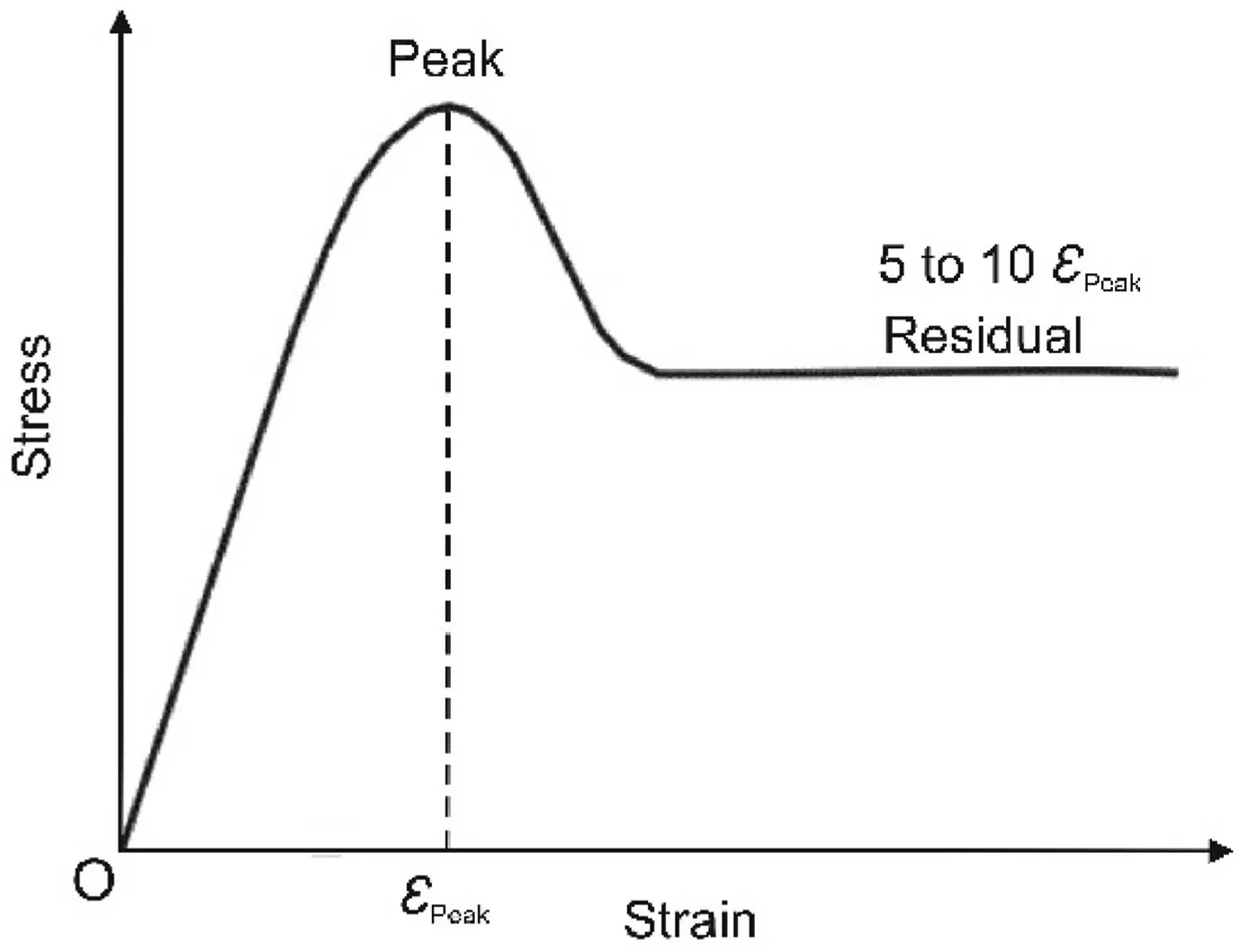
Fig.1.A typical strain-softening curve of rocks (Cai et al.,2007;Peng et al.,2017).
This paper aims to develop a method for estimating the postfailure parameters as the function of deformability and peak strength parameters,which can be readily determined using the conventional laboratory tests.The method takes into account the zone size effect,interface effect,and treatment of dilatancy.To this end,an innovative attempt has been made to develop numerical models to estimate these strength parameters based on the iterative manual back-analysis of laboratory testing results of coal specimens for differentw/hratios for different coal seams in India.The uniaxial compression test results of specimens withw/hratios of 0.5-13.5 from six Indian coal seams were selected for this purpose.In these tests,the displacement loading continued significantly beyond the strain corresponding to peak strengths to record the residual strength and strain-hardening characteristics due to the reconsolidation of the failed material.The results of the calibrated models were utilized to develop a model in the form of a set of best-fit relations to estimate the post-peak strength parameters as the function of readily available peak strength and deformability parameters.The developed model has been validated against the laboratory-observed triaxial testing results reported by Medhurst(1997) regarding stress-strain,volumetric-axial strain,and the failure characteristics.
2.Review of the literature
The development of stiff servo-controlled testing machines has allowed rock mechanics workers to study the post-peak behavior of the rocks.Based on the post-peak response,the rock behavior can be categorized into Class I and Class II (Wawersik and Fairhurst,1970).Class I represents a gradual loss of load-bearing capacity due to controlled propagation and coalescence of cracks.On the other hand,Class II shows sudden rock failure due to uncontrolled propagation and coalescence of the cracks.This emergent macroscopic rock behavior,however,is governed by a complex interaction between the microcracks and heterogeneous stress field set-up due to a mismatch of elastic stiffness of grains and the presence of micro-flaws (cleavages,strings of grain boundary cavities,and pores) (Sinha and Walton,2020).
Fig.2a and b illustrates the typical macro-mechanical response of the rocks to compressive loading.During the initial loading phase,the pre-existing micro-flaws are closed,resulting in small nonlinear behavior till pointA,which decreases the rock volume.Subsequently,the rock undergoes elastic deformation accompanied by volumetric decrement till pointB.PointBrepresents the onset of crack initiation (crack initiation threshold),wherein new microcracks are formed and propagated stably as the local tensile stresses exceed the strength near flaws or at the grain boundary.The rate of volumetric compaction decreases during this phase of loading due to newly formed cracks,and the volumetric-axial strain curve departs from its linear trend.As the loading continues from pointConwards,the crack density in the rock is sufficient for localized coalescing in the shear band or forming a tensile spall.PointCmarks the beginning of unstable growth of cracks (crack damage threshold) and relative dilation as the volumetric strain is minimum at this point and increases hereafter.
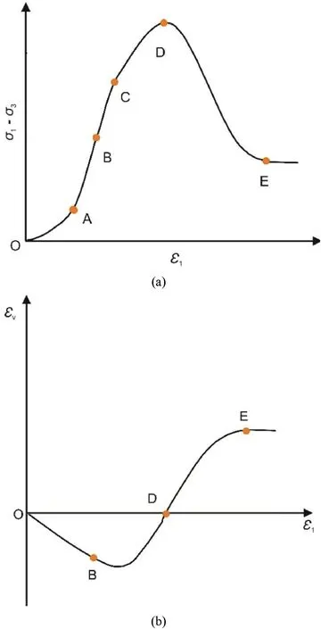
Fig.2.A typical stress-strain behaviour of intact coal under triaxial compression: (a)Differential stress versus axial strain and (b) Volumetric strain (εv) versus axial strain(ε1) (Pourhosseini and Shabanimashcool,2014) (σ1 and σ3 are the major and minor principal stresses,respectively).
After attaining the peak strength at pointD,the rock strength decreases continuously(strain-softening behavior) until it reaches the residual strength.Although the rock undergoes relative dilation from pointConwards,the net volumetric strain is zero at the peak strength (pointD),as the volumetric expansion due to the formation of new cracks is equal to the volumetric contraction due to the closure of the pre-existing flaws.The rock dilation is maximum close to the peak strength and gradually decreases to attain a stable value at the residual strength (pointE).This post-peak behavior,however,is subjected to loading conditions,the shape(w/h)of the specimen,and shear strength of contact surfaces between the specimen and the loading platens (Das,1986;Fang and Harrison,2002;Prassetyo et al.,2019).
Previous researchers have investigated the influence of confinement on the emergent mechanical behavior of rock structures by conducting triaxial and uniaxial compression tests on specimens with differentw/hratios (Medhurst and Brown,1998;Yuan and Harrison,2004;Prassetyo et al.,2019).The confining pressure provides confinement in the triaxial setup.Instead,in the uniaxial loading condition,it is generated by the interface effect combined with the post-peak and residual strengths in the rib and yielded zones around the elastic core (if any) (Mohamed,2003;Rashed and Peng,2015).They showed that the peak strength,postpeak strength,and residual strength increase while the slope of the post-peak stress-strain line decreases with increase of the confinement.The difference between the peak strength and the post-peak strength also decreases with increasing confinement.On the other hand,the dilation of the rock shows a decreasing trend with the increase in confinement.Additionally,the volumetric compaction phase is prolonged,resulting in delayed onset of dilation along the axial strain axis.Generally,two macroscopic failure modes,axial splitting and shearing,are observed in the laboratory setting of rock,which is governed by the rock properties and the loading conditions.While axial splitting is observed with low lateral confining stresses,the failure mode transitions to shear failure with increased lateral confinement (Medhurst and Brown,1998).Additionally,the inclination of the shear plane decreases with increase in the confining stress.
In addition to the confinement provided by thew/hratio of the specimen,the properties of contact surfaces between the coal and surrounding loading unit also influence the peak strength,postpeak strength,and residual strength (Lu et al.,2008).Prassetyo et al.(2019) noted that the interface friction significantly influences the coal strengths.Four distinct friction zones can be identified at the top end-surface of coal specimens depending on the friction experienced by these surfaces during the loading history(see Fig.3).These four zones from the free face of the specimen are:(i)rib zone-with little confinement as it is exposed to the free surface;(ii) transition zone -experience intense friction;(iii) intermediate zone -experience light friction;and (iv) core zone -experience no friction and highly confined.This implies that the percentage of the core zone decreases with decreasing interface friction and can be negligible even in the case of a highw/hratio(up to 12) if the interface friction combined with the strength is low.
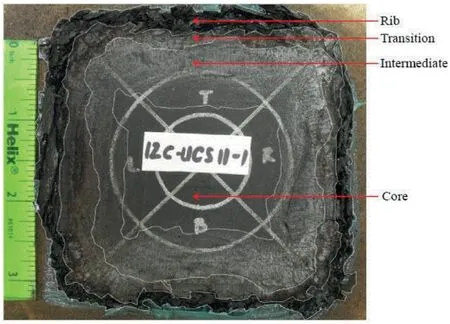
Fig.3.The four zones identified on the top end-surface of a coal sample of w/h=12(Prassetyo,2011).
With respect to reproducing this behavior using numerical modeling,microscopic and macroscopic approaches have been used over the years within the framework of continuum modeling(Pourhosseini and Shabanimashcool,2014).The microscopic response is governed by the mechanical behavior of the microstructures.The implementation of this approach in the numerical modelling codes has severe limitations,as it requires several parameters,including the microcrack’s initial length,that are extremely difficult to determine(Shao et al.,2006;Wu et al.,2006).On the other hand,the macroscopic approach employs plasticity theory,wherein the failure criterion is allowed to shrink with the evolution of inelastic strain (Lin et al.,2018).The non-associated flow rule is usually utilized to define the post-peak rock deformation.
The strength parameters associated with the peak strength are degraded to their residual values as the damage evolves in the rock,enabling the shrinkage of the failure criterion to reproduce the nonlinear softening and residual strength behavior (Itasca,2015).The damage in the rock is quantified by plastic shear strain.The Mohr-Coulomb and Hoek-Brown failure criteria have been extensively used to model the mechanical attributes observed in both field and laboratory settings.However,the Mohr-Coulomb criterion is generally preferred over the Hoek-Brown criterion because its parameters (inherent cohesion and internal friction angle) have physical meanings.The dilation angle,which characterizes the dilatancy of the rock,describes the post-peak volumetric increase due to the shear yielding of rock elements (Vermeer and de Borst,1984).Experimental studies indicate that the dilation angle as a fundamental and pervasive property of rocks (Cook,1970) is strongly dependent on the confining stress and plastic shear strain(Yuan and Harrison,2004;Alejano and Alonso,2005).
Adequate representation of contact surfaces at the top and bottom of the specimen is crucial for the accurate modeling of stress-strain behavior.Iannacchione (1991) indicated that the strain-softening model without proper representation of the contact surfaces could develop unrealistically high confining stresses,resulting in under-design of the pillar for a higherw/hratio (w/h>10).The development of confinement and the resultant failure pattern in the pillar is critically dependent on the shear strength properties of the contact surfaces (Gale,1998;Peng,2006).Confining stresses and rock strengths increase with the interface shear strength(Rashed and Peng,2015).Lu et al.(2008)noted that the difference in confining stress with thew/hratio was pronounced with the interface having high shear strength.Babcock(1985) noted that the magnitude of tensile stress developed along the horizontal plane of the specimen with softer end constraints increased,causing a decreasing trend of peak strength with an increasingw/hratio.
Several researchers have noted that Young’s modulus increases with confinement (Zisman,1933;Brown et al.,1989;Cuss et al.,2003;Arzúa and Alejano,2013).A few others considered the average rock modulus under different confinements as the representative modulus of the rock(Medhurst and Brown,1998;Mohan et al.,2001;Jaiswal and Shrivastva,2009;Pourhosseini and Shabanimashcool,2014).On the other hand,the test results of uniaxial compression tests reported by Das (1986) and Prassetyo(2011) on the coal samples did not reveal any contrasting difference in the modulus with the change in thew/hratio.
3.Methodology
In the macroscopic approach,three different methods can be practiced based on the degradation of strength parameters to enable shrinkage of the peak failure criterion:
(1) Only cohesion is degraded (cohesion loss method) based on the argument that the internal friction angle depends on the surface conditions,which remains primarily unaltered during the damage process(Pourhosseini and Shabanimashcool,2014;Jiang et al.,2017;Le et al.,2018;Peng and Cai,2019);
(2) Cohesion is degraded and friction angle is mobilized from its initial value from low to the peak (i.e.cohesion weakening and friction strengthening (CWFS) method) based on the assumption that the frictional component of strength is active when there is a movement against the surface.This happens only after the crack formation,leading to loss of cohesion(Hajiabdolmajid et al.,2002;Edelbro,2009;Renani and Martin,2018;Walton,2019);and
(3) Both cohesion and friction angle are degraded based on the theory that the effective friction angle of the surface is the summation of the primary friction angle of the rock and the roughness angle (Mohan et al.,2001;Wang et al.,2015;Bai et al.,2017;Feng et al.,2019).The effective friction angle reduces due to the shearing of the asperities with the movement along the so-called shear plane.
The primary aim of this study is to develop a method for simulating the post-peak characteristics of coal specimens with varyingw/hratios using the back-analysis technique.To achieve this goal,the aforementioned three approaches were initially examined for their capabilities to model this behavior in a preliminary study.The most appropriate approach was then selected for further detailed studies,where the stress-strain behavior of different specimens was modeled.The laboratory test results of servo-controlled uniaxial compression tests reported by Das(1986)were used for this purpose.
To model the stress-strain behavior,the Mohr-Coulomb strainsoftening (MCSS) constitutive model provided in finite difference code FLAC3Dversion 5.01(Itasca,2015)was employed.The FLAC3Dformulation incorporates the complete dynamic equation of motion,enabling a stable solution scheme even for the nonlinear material,with the possibility of physical instability(sudden failure of specimen or pillar).Moreover,the nonlinear strain-softening or hardening behavior was replicated in the model by prescribing variation in Mohr-Coulomb material properties,such as cohesion,friction,and dilation,as functions of plastic shear strain.The default‘Local’ damping mode was also utilized in this study.
3.1.Material properties
The study by Das(1986)reported the stress-stain curves of coal specimens with varyingw/hratio from six Indian seams,i.e.Kargali,XII,Kenda,Singhpur,Jambad,and Uchitdih,located in Raniganj,Jharia,and South Karanpura coalfields.With respect to cylindrical coal specimens,thew/hrepresents the ratio of diameter to height of the specimen.The specimens from Uchitdih and Kenda seams hadw/hratios of 0.5,1,2,3,4.5,6.75,9 and 13.5,while Singhpur seam hadw/hratios of 0.5,1,2,3.2,4.5,7.7,9,and 13.5,and Jambad,Kargali,and XII seams had thew/hratios of 2,3,4.5,6.75,9,and 13.5 (Das,1986).The peak strength and deformability parameters were referred from the laboratory test results reported in Das and Sheorey (1986) and Sheorey et al.(1986).The parameters included the uniaxial compressive strength (UCS) and elastic modulus (E) determined by the uniaxial compression tests(Sheorey et al.,1986),and internal friction angle evaluated from the servo-controlled triaxial testing using Hoek and Franklin cell (Das and Sheorey,1986).The cohesion was estimated from the UCS and the friction angle,assuming that the coal material follows the MC constitutive model.The UCS and elastic modulus ranged from 19.5 MPa to 47.48 MPa and 1.82 GPa to 4.87,respectively,while friction angle varied between 35°and 51°.The laboratorymeasured values for the different coal seams are shown in Fig.4.
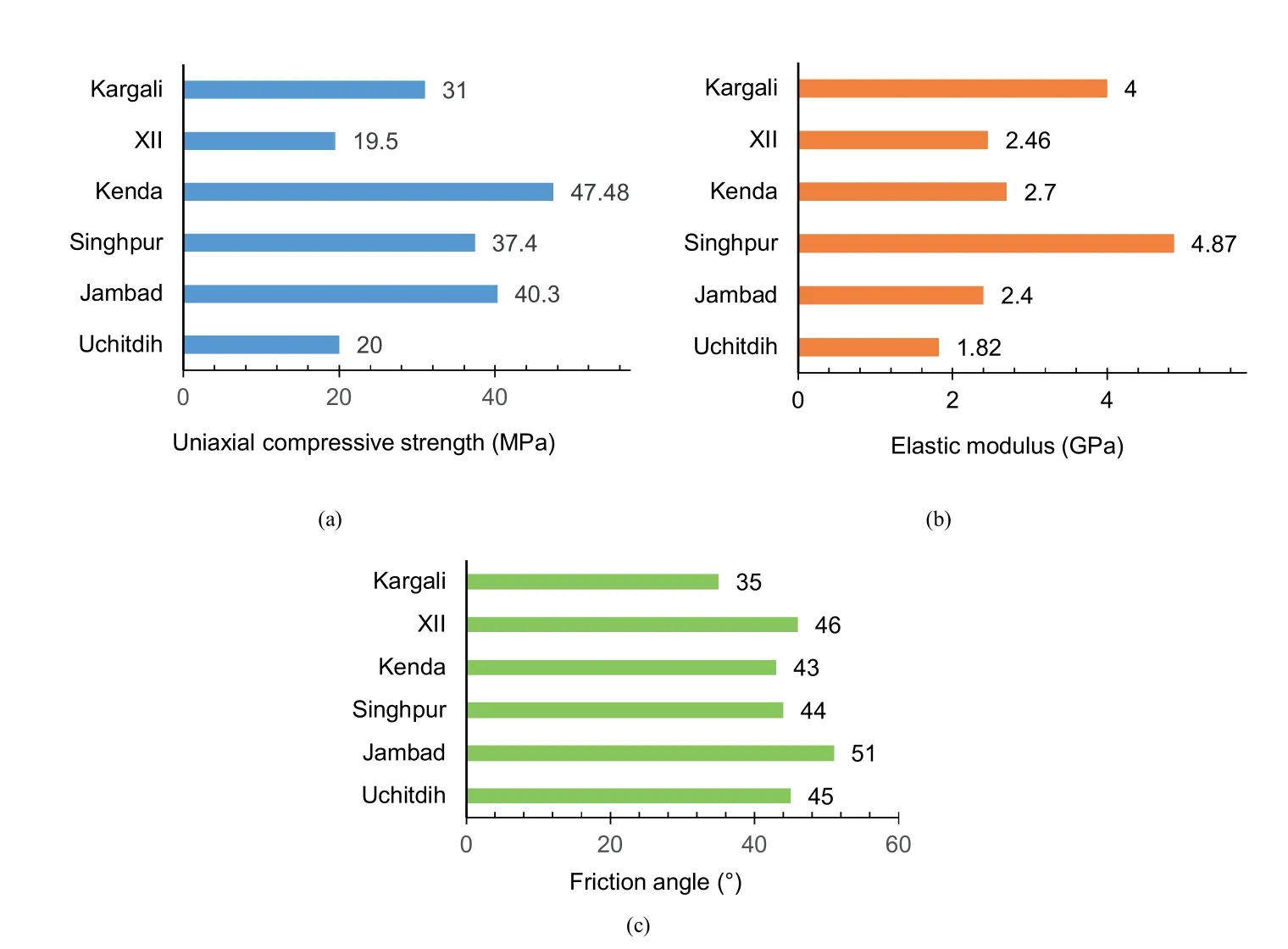
Fig.4.Charts depicting the input properties of coal in the model: (a) Uniaxial compressive strength,(b) Elastic modulus,and (c) Friction angle.
Previous laboratory tests investigating the dependency of postfailure behavior on the pre-peak deformability and peak-strength parameters showed that the modulus,in terms of the post-failure strengths,is positively correlated with the UCS andEfor different rock types(Tutluo˘glu et al.,2015).Therefore,it can be hypothesized that the deformability and strength parameters significantly influence the post-failure strength parameters,and the values of the latter can be estimated in terms of the former.The wide range of aforementioned parameters in this study provides a reasonable basis for testing this hypothesis.
The built-in interface elements in FLAC3Dare characterized by Coulomb sliding and (or) tensile and shear bonding,which are utilized to reproduce the mechanical behavior of the contact surfaces in the coal-steel platens at the top and bottom ends of the specimen.While the strain-softening behavior of the interface representing the given surfaces has been recognized by a few researchers(Wu et al.,2011;Gu and Ozbay,2014;Zhang et al.,2015),the linear Coulomb failure criterion was adopted in this study for simplicity purpose.The mechanical behavior of the interface is governed by the normal and shear stiffness,cohesion and tensile strength,and friction and dilation angles.
During the preliminary numerical modeling study,it was found that the interface’s elastic stiffness properties and tensile strength are not critical for the calibration process.Instead,the shear strength properties dominate the calibration process.Nevertheless,the stiffness of the interface cannot be set to a very high value as this would lead to a lengthy model response and delayed convergence of the solution due to the stiffness-based mass scaling(Itasca,2015).Hence,the stiffness was set to 10 times the equivalent stiffness of the neighboring smallest zone in the softer rock along the interface (see Eq.(1)),as suggested in the manual:
whereK0is the stiffness;KandGare bulk and shear moduli,respectively;Δzsminis the size of the neighboring smallest zone.
The other material properties,such as friction,cohesion,and dilation and tensile strength,were used from the direct shear test results in Rashed and Peng (2015).They conducted these tests to determine the shear strength of contact surfaces between the coal specimen ends and the machine platens.A nominal cohesion value of 1 kPa was considered,while the dilation angle was estimated as 7°based on the preliminary studies as a part of the calibration process.Table 1 shows the final interface properties used in this study.
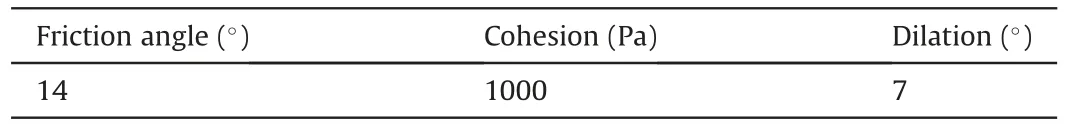
Table 1Interface properties considered in the model.
The mobilization of the dilation angle of the coal with plastic shear strain and the confining stresses was modeled by implementing the Walton-Diederichs (W-D) model (Walton and Diederichs,2015a) (see Eqs.(2)-(5)) using the embedded FISH language.The W-D model requires a minimum number of input parameters as compared to its counterpart models and can be easily estimated and implemented in the numerical model.The model considers a piecewise linear function for mobilization of prepeak,peak,and post-peak dilation angles,as indicated in Fig.5.
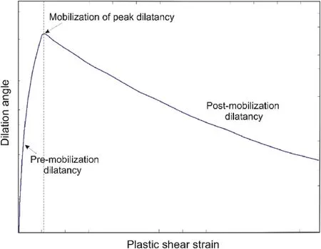
Fig.5.A schematic diagram illustrating different parts of a typical dilation angle curve.
where ψ(σ3,γp) is the instantaneous dilation angle corresponding to a confining stress and plastic shear strain (γp),ψPeak(σ3) is the peak dilation angle corresponding to a confining stress,and φPeakis the peak friction angle.γ*is the parameter to define postmobilization decay of the dilation angle.
The value of UCS can be determined from the uniaxial compression test in a laboratory set-up.The constant α0defines the curvature for the pre-mobilization portion of the curve for σ3=0,while α′defines change in curvature as a function of σ3.On the other hand,γmdefines the plastic shear strain at peak dilation,and γ0and γ′define the post-mobilization decay rate of the dilationangle for σ3=0 and non-zero σ3,respectively.The values of γm,γ0and γ′for coal were referred from Walton and Diederichs (2015a),whereas α0and α′were estimated based on a preliminary study(Table 2).

Table 2Input parameters of the W-D dilation angle model used in the numerical model.
3.2.Model generation
The geometry of specimen model included a cylindrical coal specimen with a diameter(D)of 54 mm and a height determined by thew/hratio,as well as disc-shaped steel platens at the top and bottom ends of the specimen.The interface elements were utilized to model the contact surfaces between the platens and specimen.To construct the models with differentw/hratios,the specimen height was varied while the diameter was 54 mm,following the procedure followed by Das (1986) for specimen preparation.The diameter and the thickness of platens were 55 mm (D+1) and 18 mm(D/3),respectively(Bieniawski and Bernede,1979).An effort was made to maintain uniform zone size throughout the specimen and platen volume by generating grids using the meshing plug-in Griddle 2.0 and Rhinoceros 5.0 CAD system (Itasca,2020).The surfaces of the specimen were meshed in‘AllQuad mode’using the‘unstructured surface mesher’ tool to generate pure quadrilateral meshes by setting the maximum and minimum edge lengths at the desired zone size.With these quadrilateral surfaces as the boundaries,the ‘unstructured volume mesher’ function was used to generate ‘conformal hexagonal’ elements in the model.This grid generation scheme ensured that the length of all the edges of the zones was nearly equal.A total of 10 model geometries corresponding tow/hratios of 0.5,1,2,3,3.2,4.5,6.75,7.7,9,and 13.5 were set up,and their output meshes were imported in FLAC3D.Fig.6 illustrates the geometry of the discretized models with differentw/hratios.
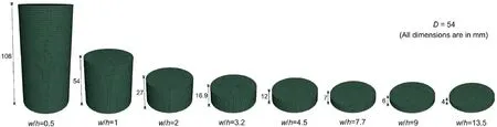
Fig.6.Geometry of coal specimen models of different diameter to height (w/h) ratios (unit in mm).
Three element sizes of 0.5 mm,1 mm,and 2 mm were considered during the model calibration to evaluate and quantify its effect on the post-peak mechanical behavior of the specimen.The horizontal and vertical displacements at the top and bottom of themodel were restricted by applying fixed boundary conditions(Fig.7).The bottom platen was fixed to replicate the existing condition in the laboratory set-up,whereas the top of the other platens was fixed to prevent rebound during displacement-controlled loading.It was observed that the rebound of the top surface of the model resulted in erroneous results.A constantz-velocity parallel to the specimen axis was applied.The displacementcontrolled loading resulted in compressive stress,while the confining stresses developed in the specimen due to the shear resistance offered by interfaces at the specimen ends.
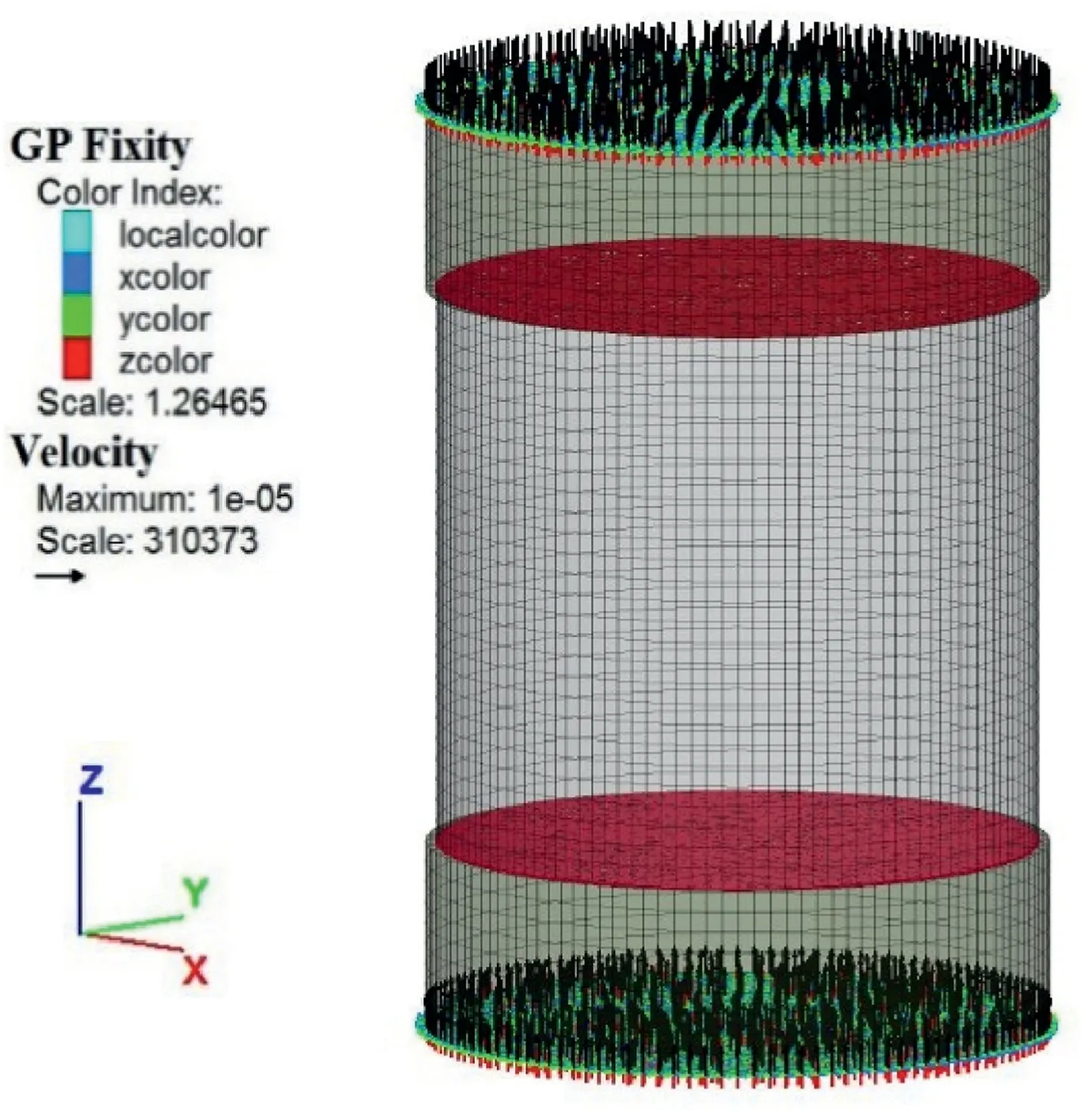
Fig.7.Boundary showing applied velocity at the ends of coal specimen with w/h=1.
The solution scheme in FLAC3Dworks on the concept of‘frozen velocity’,wherein the neighboring zones are unaffected when the calculation cycle is performed for a zone in question.It requires a lower velocity to be applied at the specimen ends to mimic the static uniaxial loading process.On the contrary,the limitation of computational time necessitates the applied velocity to be higher.After several trials,the applied velocity was fixed at 10-5mm/timestep as a trade-off between the two conditions.
3.3.Simulation of strain-softening behavior
Before embarking on the full-fledged calibration process,a preliminary study for a single coal seam (Singhpur middle) with a zone size (zs) of 2 mm was conducted for differentw/hratios to check the viability of all three methods: CWFS,cohesion loss,and simultaneous degradation of cohesion and internal friction angle.In the CWFS method,the initial values of its parameters,namely,the peak cohesion,initial friction angle,residual cohesion,mobilized friction angle,plastic strain limits to reach residual cohesion and the mobilized friction angle,were estimated following the guideline suggested in Walton (2019).Later on,their values were varied in a range based on the published case studies(Hajiabdolmajid et al.,2002;Diederichs,2003;Edelbro,2009;Zhao et al.,2010;Edelbro et al.,2012;Walton et al.,2014,2016;Walton and Diederichs,2015b) in an attempt to calibrate the model response against the laboratory observed characteristics.The outcome of this study suggested that this method was unable to simulate the post-peak mechanical behavior for a highw/hratio(>3),which had a strain-softening nature.This inability can be attributed to the reason that this method was primarily developed for brittle rock with relatively limited jointing(geological strength index(GSI)>70),deforming through an extensile cracking process.In contrast,the failure behavior of coal specimens with a highw/hratio is dominated by the shear mechanism (Sinha and Walton,2018).
Following this,the capability of the strain-softening methods,including the cohesion loss method and the method involving simultaneous degradation of both cohesion and friction angle,were tested.These methods require six parameters: peak cohesion(cPeak),peak friction angle(φPeak),residual cohesion(cRes),residual friction angle(φRes),plastic strain limits to reach residual cohesion() and residual friction angle () along with mobilisation of dilation angle(ψ)as a function of evolving plastic shear strain(eps).In the case of the cohesion loss model,φReswas set to φPeak.Thus,it required only four parameters.ThecPeakand φPeakwere taken equal to their laboratory observed values.During the calibration process to estimate the rest of the parameters,the cohesion drop rate(cDrop)and friction angle drop rate(φDrop)with the inelastic strain were introduced to replaceand,respectively,andcResand φReswere taken as the percentage of their peak values (cPeakand φPeak)for the sake of their more straightforward implementation in the numerical model.HighercDropand φDropimply a smalland,respectively and vice versa.These parameters were assumed to follow the bilinear-decay profile during the softening regime(Fig.8).
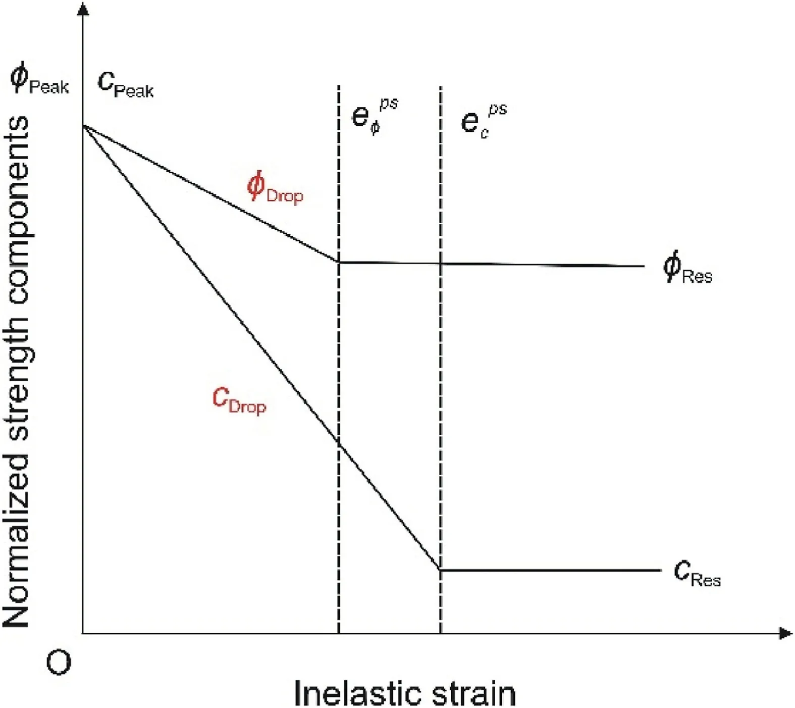
Fig.8.Schematic illustrating the evolution of strength components,friction angle and cohesion as a function of inelastic strain in the MCSS constitutive model.
The entire calibration exercise was performed in three stages.In the first stage,sensitivity analyses were conducted to assess the influence of four parameters (cDrop,φDrop,cRes,and φRes) on the three calibration targets: peak strength,residual strength,and post-peak deformation slope.For this,one parameter varied at a time while the other three remained constant.The initial range of variation in these parameters was decided based on the previous studies (Mohan et al.,2001;Jaiswal and Shrivastva,2009;Shabanimashcool and Li,2012;Yan et al.,2013;Zhao et al.,2014;Wang et al.,2015;Bai et al.,2016;Jiang et al.,2017;Zhang et al.,2019;Feng et al.,2019).These studies used the strain-softening method to design and evaluate the stability of coal mining structures based on the back-analyses of failure patterns,stress-strain curves,displacement,stress in the coal pillars and samples,and the peak pillar strength.The parameterscDropand φDropvaried in these studies from 16 MPa to 423 MPa and 400°-1200°,respectively,for unit plastic shear strain;whilecResand φResranged 0%-35%and 71%-88%,respectively.The peak strength was significantly affected bycDropand φDrop,and decreased with their increment.The residual strength was directly correlated tocResand φRes.The post-peak deformation slope,on the other hand,was significantly influenced by φDrop,cResand φResand increased with a decrease in φDropand an increase incResand φRes.Further,it was also noted that variations in cohesion parameters,cDropandcRes,alone were not sufficient to meet the calibration targets,especially the post-peak deformation slope and residual strength.Hence,the cohesion loss method was unable to model the complete stress-strain characteristics of the coal specimens.
Based on the outcomes of this sensitivity analysis,a full-fledged calibration process was performed in the second stage by considering a change (within the range mentioned above) in all four parameters,cDrop,φDrop,cResand φRes,concurrently as their interactions might have a significant influence on the model outcome (Leroueil and Tavenas,1981;Oreste,2005).Accordingly,the combination of the parameters was selected and adjusted to meet the calibration target.Fig.9 summarizes the scheme adopted for calibrating the model against the laboratory-observed characteristics for a given zone size.Eventually,it was noted that more than one combination of parameters could reproduce the laboratory characteristics for a givenw/hratio and zone size.This nonuniqueness in the parameters could be attributed to the fact that the number of model parameters (four) are greater than the calibration targets(three)(Aster et al.,2012;Walton,2019).In addition,the post-peak deformation slope was automatically fitted when the peak and residual strengths were captured in the model,which effectively reduced the number of calibration targets to two.For minimization of the non-uniqueness,the optimum combination was chosen based on the assumption that the effectivecResand φResshould increase with thew/hratio of coal specimens of a particular seam,as increasing confinement would inhibit the mobilization along the so-called shearing plane (Cai et al.,2007;Walton and Diederichs,2015a).
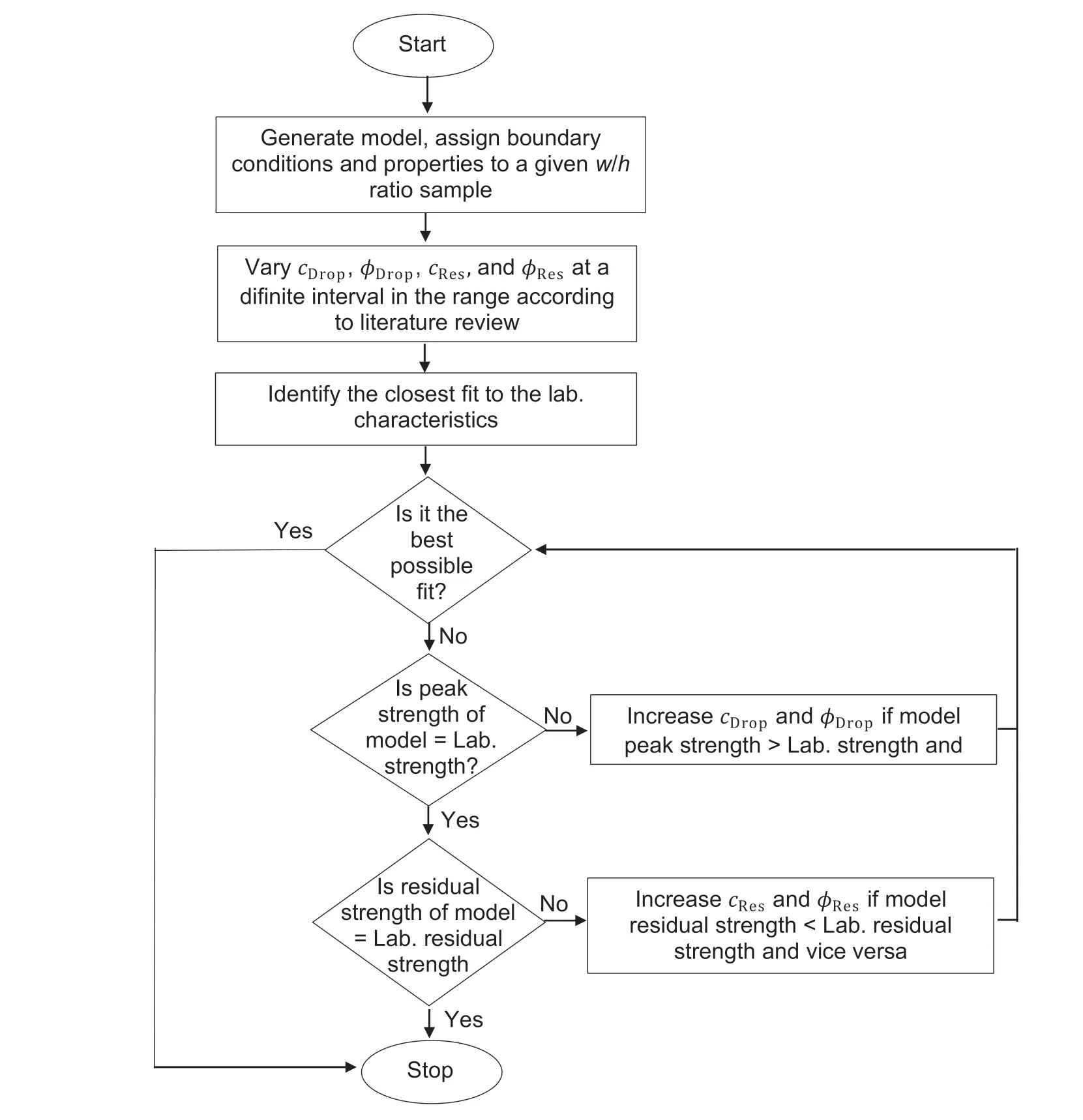
Fig.9.Iterative technique for calibrating the modeled stress-strain curve against the laboratory observed behavior for a given w/h ratio sample.
In the third stage,a similar process was followed to calibrate the model for two other zone sizes of 0.5 mm and 1 mm.The best possible combination of parameters estimated previously for a zone size of 2 mm was taken as the reference,and all the calibration targets could be matched by changing onlycDrop.ThecDrophad to be decreased with a decrease in zone size to meet the calibration requirements.The models belonging to the remaining five coal seams were also calibrated following similar stages.Table A1 compiles the final set of best-fit parameters for 126 calibrated models of differentw/hratios pertaining to the six coal seams and the three-zone sizes.
3.4.Development of a best-fit model for estimating post-failure parameters
The preliminary analysis of the best-fit parameters (Table A1),corresponding to the 126 calibrated models,indicates that although the drop rate and residual values of post-peak friction angle play a vital role in characterizing the strain-softening behavior,their values (φDrop=100°,300°and 500°for unit plastic shear strain;φRes=50%and 70%)are broadly constant for different ranges ofw/hratio and zone size for different coal seams.This observation is consistent with(Mohan et al.,2001;Cai et al.,2007).The post-peak cohesion parameters control different strain-softening characteristics as well as the deformational and strength properties of the coal samples across theirw/hratio and zone size.The strainsoftening behavior was reproduced in this study by enabling the shrinkage of the Mohr-Coulomb yield function with the accumulated plastic shear strain:
where ν andEare the Poisson’s ratio and elastic modulus,respectively.
In addition,the axial strain(ε1)can be decomposed into elastic and plastic axial strain ():
Therefore,from Eqs.(7) and (8),the relation between axial stress and strain can be written as
On substituting Eq.(9) in Eq.(6),we have
Moreover,during the yield and stain-softening stages,as the stress states are restricted by the initial yield and shrinking yield envelopes,the cohesion at these stages can be expressed as
wherecξis the instantaneous cohesion at post-peak softening stage,and σ3is the function ofw/hratio,i.e.σ3=f(w/h).
Based on this relation and the sensitivity study conducted as a part of the calibration process discussed in Section 3.3,the postpeak cohesion was hypothesized to be the function ofw/h,E,cPeak,φPeak,and zone size.SincecPeakwas evaluated based on φPeakand UCS using Mohr-Coulomb criterion,UCS instead ofcPeakwas considered when developing the empirical model.The relation between the above-mentioned parameters(independent variables)andcDrop(dependent variable) were observed to be nonlinear during initial analysis,and accordingly power functions were chosen for model development.Thet-test for each independent variable was conducted to examine their significance on the dependent variable,while F-test was done to determine their overall significance.With respect tocRes,t-test implied that it was dependent only onw/hratio,but it was zero forw/h≤2.Eqs.(12)and (13) show the models developed in terms of the best-fit relations and their regression coefficient:
where σcandEare the UCS and elastic modulus of the coal in MPa and GPa,respectively.φDropand φRescan be any value of 100°-500°for unit plastic shear strain and 50%-70%of the peak friction angle,respectively.However,φDropof 300°-500°for unit plastic shear strain is recommended for the conservative design of coal structures.Fig.10 compares the outcome of the best-fit relations and the calibrated models on a logarithmic scale.The model projections are in close agreement with the numerical modeling results.

Fig.10.Comparison between the predicted values using best-fit relations and the numerical model for(a)Cohesion drop rate(cDrop)and its(b)Residual value(cRes).Note that the data points in residual cohesion plot (b) only include specimens with w/h ≥ 2.
The above relations confirm the hypothesis that the post-failure strength parameters are significantly dependent on the deformability and peak strength parameters,and their values can be estimated in terms of the pre-peak deformability and peak strength parameters.The dependency of post-failure cohesion parameters onw/hratio of the specimen is in line with the findings of Lin et al.(2018),who reported that the post-failure strength parameters are function of confining stresses based on the triaxial compression tests results.
4.Results
In this section,the results of the best-fit parameters for coal samples of Singhpur middle coal seam and zone size of 2 mm are presented.The results related to other seams and different zone sizes are not discussed owing to their similarity.The built-in FISH functions were used to monitor axial stress,axial strain,volumetric strain,confining stress,dilation angle,and accumulated plastic shear strain at every 100 timesteps for each zone.The values retrieved were then averaged over the whole sample using a FISH routine to represent the emergent mechanical response and deformation behavior of the specimen.Therefore,the parameters used in this section to study the stress-strain and deformation behavior represent the average value for the specimen.
Fig.11 compares the laboratory-observed stress-strain curves of differentw/hratio specimens with the calibrated models.The continuum models well replicated the overall shape of the curves.The residual strengths increased with thew/hratio,whereas the post-peak deformation slope decreased in both the laboratory and the model observed curves.A perfect brittle behavior and a very high rate of strength drop were observed for aw/h ratio of 0.5 and 1,whereas nearly plastic behavior and a nominal drop rate were noted for aw/hratio of 7.7.The specimens havingw/hof 2,3,and 4.5 showed strain-softening nature through a gradual loss of strength from their peak to the residual values,while a continuous strain-hardening characteristic was noted forw/hratio greater than 7.7.Further,the pre-peak curves were mostly linear as the grainscale heterogeneities,which primarily governs the nonlinear behavior related to crack initiation and crack damage (Ghazvinian et al.,2014;Farahmand and Diederichs,2015;Wang and Cai,2019) that were not considered in this model.
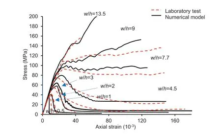
Fig.11.Model and the laboratory observed stress-strain plots of the coal samples of Singhpur middle seam for varying w/h ratio.
These calibrated models were utilized to investigate the strength and deformation behavior of the coal specimens for varying differentw/hratios and the underlying mechanisms.Fig.12 shows the volumetric-axial strain curves for the calibrated models representing the variation in the deformation behavior of pillars for differentw/hratios.In the usual way,the onset of dilatancy can be defined as the point where the curves depart from the linear elastic contraction (Yuan and Harrison,2004).The onset of dilatancy is delayed with increase in thew/hratio,resulting in more elastic contraction.The rate of dilatancy (defined as the slope of volumetric-axial strain curves after the onset of dilatancy)is reduced with the increasingw/hratio.The point that a curve intersects the axial strain axis represents the dilatancy at the peak strength,where the compaction is equal to the volumetric expansion.The maximum dilatancy is noted forw/h≤3,and it is almost zero for largerw/hratio.It decreases gradually for axial strain beyond the peak strength and becomes constant at the strain corresponding to the residual strength.Forw/h=4.5,the degree of compaction equals expansion as the curve overlaps the axial strain axis.On the other hand,the expansion is almost negligible for higherw/hratios as they experience continuous compaction.
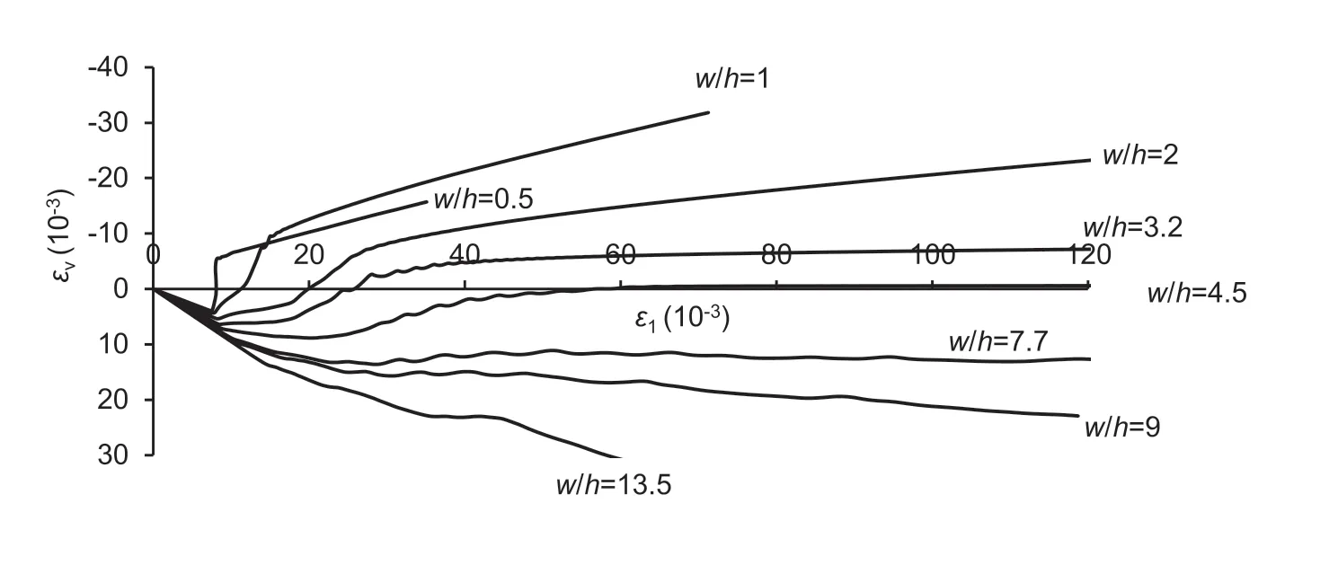
Fig.12.Volumetric-axial strain curves of the calibrated models for different w/h ratio samples of Singhpur middle seam.
Fig.13 shows the dilation angle vs.accumulated plastic strain curves for the calibrated models of differentw/hratios.It is worthy to note here that the figure illustrates the variation of dilation angle with plastic shear strain by taking into account the influence of confining stresses due to the interface effect andw/hratio in the failed zones only.Hence,dilation angle always has a positive value even for higherw/hratio.The calibrated models successfully captured the pre-peak mobilization and post-peak decay of the dilation angle.Initially,the dilation angle increases rapidly to the peak value with the plastic shear strain and gradually decreases.A loww/hratio sample shows a high peak dilation angle,which decreases with an increase in thew/hratio.For example,the peak dilation is maximum (32°) for aw/hratio of 0.5 and is minimum(11°)for aw/hratio of 13.5.The marginal decrease in the post-peak dilation angle forw/h≤1 indicates brittle failure and very low confining stresses(Alejano and Alonso,2005).Forw/h≥2,on the other hand,the rate of decrease of post-peak dilation angle reduces with the increase in thew/hratio and tends to be zero for higher plastic shear strain.
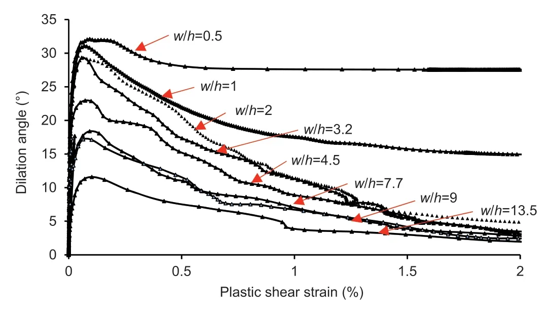
Fig.13.Dilation angle vs plastic shear strain curves of calibrated different w/h ratio models of Singhpur middle coal seam.
Fig.14 shows the role of confining stresses on the stress-strain response of the calibrated models forw/hratio of 0.5,4.5,7.7,and 13.5,exhibiting perfectly brittle,strain softening,nearly plastic,and continuous strain hardening behavior,respectively.During the displacement-controlled loading,the confining stress developed in the specimens due to the confinement provided by the interfaces and the shape effect (w/hratio).The peak strength,however,corresponds to the UCS for aw/hratio of 0.5,as the confining stress is almost negligible.The strength dropped to zero immediately after the peak,resulting in negligible residual strength.On the other hand,the strength continued to increase beyond the UCS for aw/hratio of 4.5 because of the increasing confining stress owing to restrictions provided by the interface and shape effects.Following the peak strength,continual reduction in confining stress because of the growing width of failure zone at the sample periphery resulted in softening of the strength.The sample,however,could retain considerable residual strength even after failure due to constant confining stress.In contrast,the confining stress did not reduce much for strain beyond the peak strength for aw/hratio of 7,resulting in very high residual strength,almost equal to peak strength.On the other hand,the confining stress continued to build up almost indefinitely forw/hratio of 13.5,showing continuous strain-hardening characteristics.
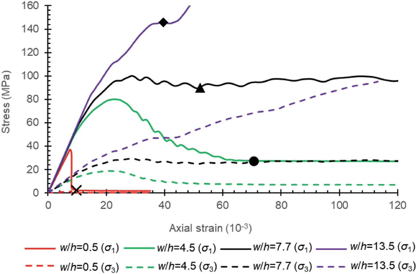
Fig.14.Stress-strain profiles of axial (solid line) and confining (dash line) stresses for Singhpur middle coal samples having w/h ratio of 0.5,4.5,7.7,and 13.5,depicting brittle,softening,ductile,and strain-hardening behavior.
Fig.15a-d illustrates the role of confinement provided by the interface and the shape effects at the residual strength,as highlighted by markers in Fig.14.The highlighted points correspond to the residual strength and,in the case ofw/h=13.5,where the curve begins to gain strength after a slight constant stress phase due to failure of the rib zones.The interface shear slip,displacement,and failure state in the sample have been presented at the top-end surface.The actual shear slip of the interface is depicted by the‘slip now’ state,while the ‘slipped in past’ occurs during the first few steps of the solution due to transient stresses,as confirmed by interface shear displacement.Note that the interface shear slip represents the failed state of the interface elements,whereas the displacement shows the relative displacement between the platens and the specimen top-surface.For aw/hratio of 0.5 (Fig.15a),the slip at the interface was limited to one-half and the shear displacement was almost zero,and no failure was observed at the top-end of the specimen,signifying that the confinement generated as the interface was negligible and failure occurred following the hour-glass failure pattern (Bai et al.,2017).This is also confirmed by findings reported in several previous studies (Mogi,2006;Hemami and Fakhimi,2014;Gao et al.,2018),stating that the effect of interface on the slender specimens (w/h≤2) was negligible.On the other hand,failure reached up to the core,and the interface slip occurred until the center forw/hof 4.5(Fig.15b).However,the interface shear displacement was restricted significantly away from the center towards the free lateral surface,and the confining effect of failed elements around the core could maintain significant residual strength.Forw/hratio of 7.7(Fig.15c),the failure did not reach the core,leading to a small region of the elastic core with no interface slippage along with limited interface shear displacement restricted to the rib region,resulting in nearly ductile behavior.On the other hand,interface slip and displacement,and failure in the specimen were restricted to a small rib region only,and a significantly large portion of the core was elastic for aw/hratio of 13.5 (Fig.15d).Hence,the specimen showed strain-hardening characteristics.These observations provide a further explanation of the work reported by (Lu et al.,2008;Prassetyo et al.,2019) about the distribution of stresses,the existence of different zones of confinement,and the presence of elastic core within the specimens of varyingw/hratio.
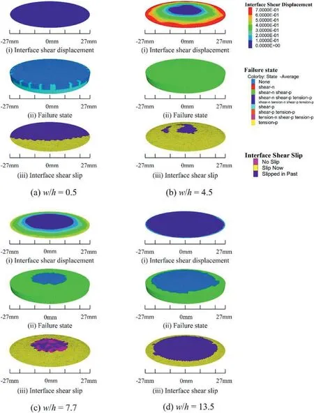
Fig.15.Slip along the interface due to shearing,failure state of the top end-surface of the coal sample,and shear displacement of the interface for samples having w/h ratio of(a)0.5,(b) 4.5,(c) 7.7,and (d) 13.5 at the loading stage highlighted by the cross,circle,triangle,and rhombus markers in Fig.14.
These observations are further supported by the deviatoric stress vs.volumetric strain curves(see Fig.16).Whenw/h=0.5,the rapid drop in deviatoric stress from the peak to almost negligible value is accompanied by large volumetric expansion,implying the brittle and sudden failure.On the contrary,relative dilation (from onward the reversal point)is accompanied by a gradual decrease of the stress forw/hof 4.5,signifying its strain-softening behavior.In addition,the volumetric expansion hardly exceeds the contraction,and significant residual stress could be maintained.In coal samples withw/hratios of 7.7 and 13.5,the marginal loss of peak deviatoric stress and very low relative dilation occurred as the limited dilation of the rib elements confined the core.Interestingly,the percentage of the elastic core for thew/hof 7.7 was less than that of the failed rib,while it was more for thew/hof 13.5 (Fig.15).As a result,no relative dilation occurred in this case.
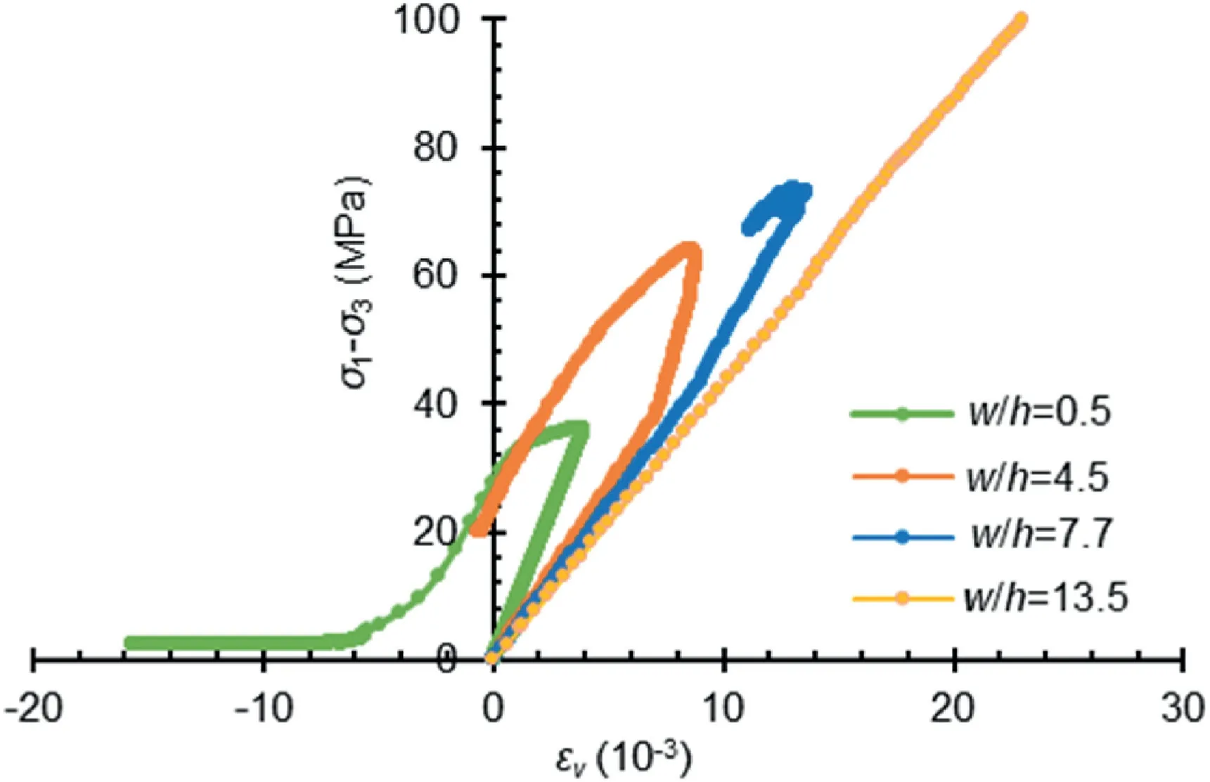
Fig.16.Model observed volumetric strain vs differential stress,illustrating relative volumetric changes due to formation of new cracks or propagation of existing ones and compaction of pores or existing cracks.
5.Validation of the statistical model
The accuracy of the developed model was validated using the triaxial compression test results reported by Medhurst (1997) on coal samples with different sizes.Medhurst (1997) conducted a series of triaxial tests on coal samples with different sizes(D=61 mm,101 mm,146 mm,300 mm) to investigate the scale effect on the mechanical behavior of coal and found that the failure mechanism changed from axial splitting to shear failure depending upon the magnitude of confining stress.The deformation modulus of 61-mm and 146-mm diameter samples were 4 GPa and 1.9 GPa,respectively.The Poisson’s ratio of 0.25 was assumed.The model geometry and boundary conditions were similar to the uniaxial test models (Section 3.2),except that the grid forces equivalent to the confining stresses applied during laboratory tests were initialized to simulate the triaxial compression tests.The post-peak softening parameters were estimated using the developed statistical model(Eq.(12) and (13)).The residual cohesion was taken as 10% of the peak value to account for the confining stresses.The peak and strain-softening parameters for the samples of 61-mm and 146-mm diameter are shown in Table 3.

Table 3Input post-failure strength parameters in the numerical models for the samples of 61-and 146-mm diameter.
Fig.17a-c and Fig.18a and b compare the mechanical and dilation behaviors obtained in the numerical model and the laboratory test for different sizes of the coal samples at different confining stresses.Medhurst (1997) repeated the triaxial test on several samples from the same coal seam.The legends of the charts show the code of coal samples from the same coal seam under the same confining stress.The model results are in close agreement with the laboratory test results,given the existing variability in the test results.They also captured the smooth trend of decreasing dilation with increasing confining stress in the coal sample.The peak and residual strengths gradually increased with the confining stress,in line with the test results.
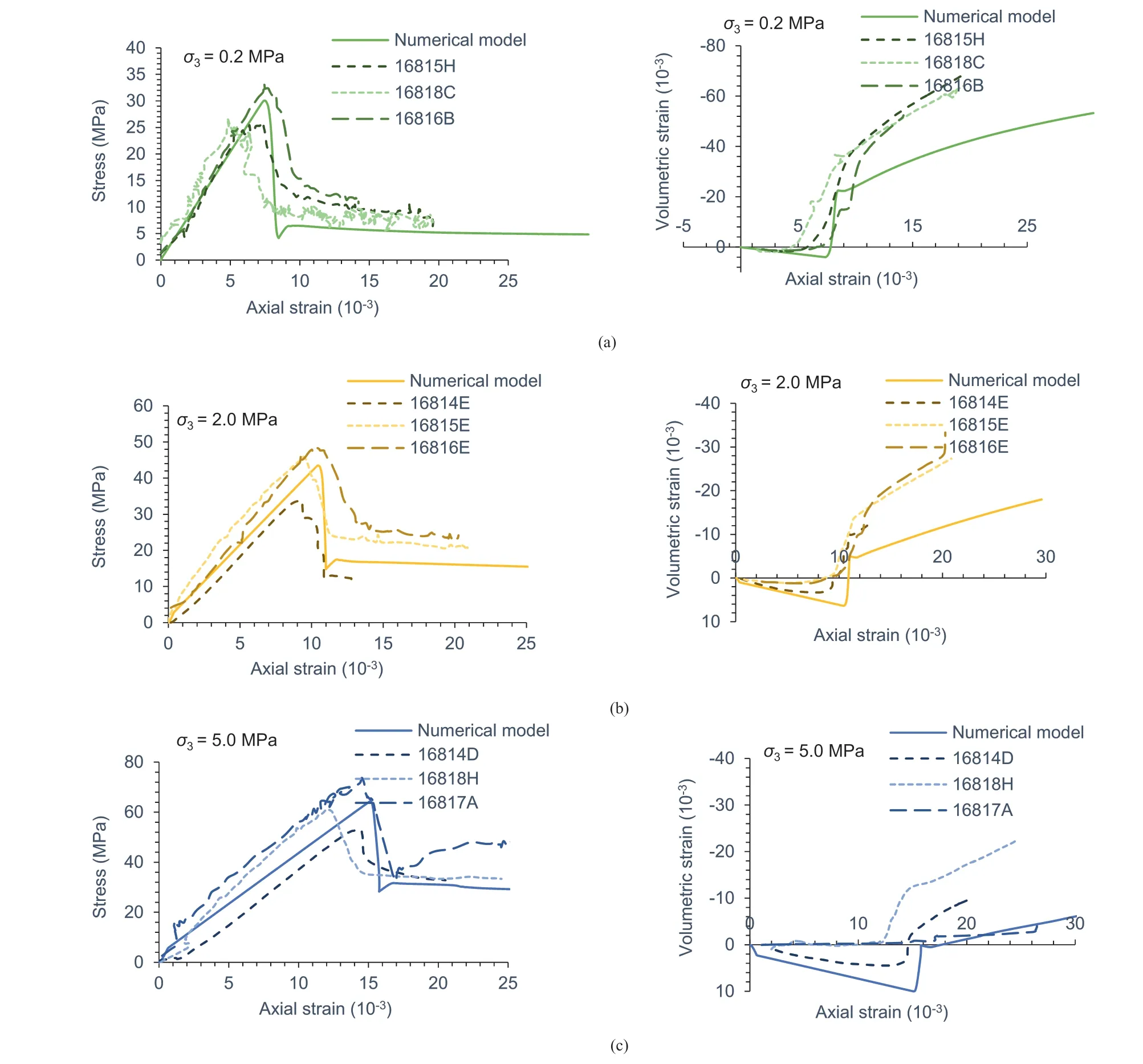
Fig.17.Laboratory tests vs numerical model results for confining stress of(a)0.2 MPa,(b)2 MPa,and(c)5 MPa for 61-mm diameter coal samples.The codes,such as 16815H,in the legend represents the sample number in the laboratory tests conducted by Medhurst (1997).
Fig.19a-c illustrates the failure patterns in the numerical models and the laboratory tests for 61-mm diameter coal samples subjected to confining stresses of 0.2 MPa,2 MPa,and 5 MPa.Axial splitting was observed at confining stress of 0.2 MPa in the laboratory specimen.However,the model showed an hourglass-shaped failure pattern.This discrepancy can be attributed to the fact that the model does not consider the micro-scale heterogeneity,as this would have required finer zone size and to the limitation of formulation of continuum modelling,which does not allow the elements to detach(Fang and Harrison,2002).The model-observed failure pattern,nonetheless,corroborates well with the laboratory and numerical model observations reported by (Bai et al.,2016,2017),who also reported a similar failure pattern.Further,the shear failure mechanism observed in the modeled samples subjected to confining stresses of 2 MPa and 5 MPa,corroborated sufficiently with the test results.
6.Discussion
Interestingly,the existing strain-softening methods used to study different geomechanical problems have considered the same post-peak strength parameters while neglecting essential factors,such as interface effect and dilatancy,to study the post-peak behavior.For these reasons,these studies could only model the peak and post-peak strengths of pillars withw/h≤5,rib failure,rib deformation,and triaxial tests.The sensitivity analyses conducted as a part of the calibration process showed that out of the existing methods,the implementation of CWFS and cohesion loss models were unable to characterize the complete stress-strain behavior of coal specimens with differentw/hratios,especially for highw/hratio.The inability of the CWFS model was mainly due to the fact that this method was primarily developed for modeling the behavior of brittle rocks under low confinement,experiencing extensile fracturing (Hajiabdolmajid et al.,2002;Walton,2019).However,this phenomenon is restricted to the superficial portions of the coal specimens with a highw/hratio (Sinha and Walton,2018) due to the reason that the dilating coal at the boundaries increases the confining stress within the deeper coal (towards core),resulting in the suppression of the formation of the extensile cracks(Diederichs,2003).As a result,the shear failure mechanism dominates at the deeper coal due to increased confinement.Therefore,simultaneous degradation of both cohesion and frictionangle was able to simulate the post-peak behavior for varyingw/hratio correctly.This observation is also supported by the findings of Renani and Martin(2018),who noted that the CWFS model shows problematic regions in the post-failure state of the specimens.They used the combination of CWFS and strain-softening models to simulate the pre-peak non-linear hardening and post-peak softening behavior of the rocks.
It was found that the parameters associated with the friction angle had a vital role,and degradation of cohesion alone(cohesion loss model) was not sufficient in defining the post-peak behavior.The friction angle drop rate and residual value were almost the same for differentw/hranges,which is in good agreement with the findings of previous researchers (Mohan et al.,2001;Cai et al.,2007).Accordingly,the post-peak behavior was primarily controlled by the degradation rate of cohesion and its residual value.The statistical analysis showed that the cohesion drop rate was positively correlated with the UCS,elastic modulus,w/hratio,and zone size,whereas it was negatively correlated with the peak friction angle.The cohesion at the residual stage becomes zero for the loww/hratio (w/h≤2).On the other hand,it varied as the functionw/hratio for greaterw/hratio.Based on analysis of the joint surface condition and block volume of the failed rocks,Cai et al.(2007) also observed that the frictional and cohesion components had different rates of reduction at the post-peak yielding stage for different GSI values,which represents the damage in the rock.Their studies implied that the frictional component decreases gradually and it has a high residual value in terms of the percentage of the peak friction angle,while the cohesive component decreases rapidly and becomes very small,which corroborates well with the findings of this study.
The different values of the cohesion for differentw/hratios in this study can be attributed to the inability of the continuum model,due to its inherent formulation,to allow the separation of discrete zones exposed to the free surface during the stress-induced damage (Sakurai,2010;Bahrani and Hadjigeorgiou,2018;Sinha and Walton,2019b).This leads to continuous strain distribution among the zones,i.e.the yielded superficial zones act as the boundary to interior zones that result in the development of further confinement from the free surface.
Further,the cohesion at the post-peak yielding stage is strongly dependent on the zone size because the zone size controls the thickness of the shear bands and the spacing between them(Itasca,2015).The fine zone size causes more softening as we travel more quickly on the strain axis of the specified softening curve because of the increased strain concentration in a band for such zone size.However,it needs to be verified whether the actual dimension of the zone or zone density,defined as the number of zones present in the unit volume,affects the overall behavior (Fang,2001).
The detailed investigation of the failure and deformation behavior using the calibrated models of coal specimens with differentw/hratios showed the importance of the interface effect and post-peak dilatancy in defining the complete stress-strain behavior.The model could reproduce the perfectly brittlesoftening-nearly ductile-continuous hardening transitions observed in the laboratory and the underlying mechanism with increasingw/hratio(Das,1986;Prassetyo,2011;Rashed and Peng,2015).For example,for a sample havingw/hof 4.5,it was noted that the specimen was able to retain substantial residual stress even after failure.The dilatancy behavior implied that coal structures withw/h≥4.5 are unlikely to undergo uncontrolled failure because the volumetric expansion after the peak strength never exceeds the volumetric compaction at the pre-peak stage.
The developed model was eventually validated by comparing the model observation of triaxial compression tests for coal specimens of 61-mm and 146-mm diameter subjected to different confining stresses.The modeling results could replicate the stressstrain and volumetric strain vs.axial strain curves successfully.The failure patterns in the models were also consistent with the laboratory observations.The specimens underwent hourglass-shaped failure for low confinement and shear failure for increased confinement (Medhurst and Brown,1998).For greater confinement,multiple shear planes were observed.
7.Conclusions
This study presented a model to simulate the complete range of the post-peak stress-strain behavior of the coal pillars and their laboratory scale samples for varying ranges ofw/htill their residual strength based on the back-analysis of laboratory observed behavior for six Indian coal seams.The baseline values of frictional and cohesion components were adopted from the literature and were further refined through model-assisted experimental understanding.
(1) The study considered the influence of mobilization of dilation angle with inelastic straining,interface effect,and zone size on the post-peak behavior of the coal.The study showed that only simultaneous cohesion and friction angle degradation could reproduce the complete mechanical response of differentw/hratio specimens.Out of the two parameters,the parameters associated with cohesion dominate in defining the post-peak behavior for differentw/hratios.However,the parameters associated with the frictional component play a vital role.
(2) This study indicated the requirement of different post-yield cohesion parameters in place of the same set of parameters,as practiced in general,to successfully reproduce the complete stress-strain behavior in the model for differentw/hratios.The post-peak cohesion drop rate was influenced by the elastic modulus,UCS,peak friction angle,zone size,andw/hratio.In contrast,the residual cohesion value was dependent on thew/hratio only.
(3) The study established that the softening behavior critically depends on the dilatancy,interface properties,and zone size.The detailed analysis of the deformational behavior of the calibrated models implied that the specimens havingw/h≥4.5 are highly unlikely to undergo sudden failure.On the other hand,specimens havingw/h≥9 can sustain a very high load and are unlikely to undergo mechanical failure.
This study focused on the post-peak softening behavior,considering that the shear failure of the coal pillars dominantly defines the post-peak strength and deformational behaviors.Although the modelling approach is able to capture the macro behavior of pillars,the simulation of the failure pattern in the rib zone needs to be further refined for its improved representation that undergoes brittle.A further study is also required to confirm whether the actual dimension of the zone or its density for a givenw/hratio determines its post-peak behavior.
Declaration of competing interest
The authors declare that they have no known competing financial interests or personal relationships that could have appeared to influence the work reported in this paper.
Acknowledgments
The authors are grateful to the Head,Department of Mining Engineering,Indian Institute of Technology (BHU) Varanasi,for backing with excellent laboratory facilities for the numerical modelling study.The views and findings expressed in this paper are the authors’ opinions and not necessarily of the organization they serve.
Appendix A.Supplementary data
Supplementary data to this article can be found online at https://doi.org/10.1016/j.jrmge.2023.06.011.
杂志排行

Journal of Rock Mechanics and Geotechnical Engineering的其它文章
- Determination of uncertainties of geomechanical parameters of metamorphic rocks using petrographic analyses
- Evaluation of excavation damaged zones (EDZs) in Horonobe Underground Research Laboratory (URL)
- On the calibration of a shear stress criterion for rock joints to represent the full stress-strain profile
- Effect of dynamic loading orientation on fracture properties of surrounding rocks in twin tunnels
- Experimental study on the influences of cutter geometry and material on scraper wear during shield TBM tunnelling in abrasive sandy ground
- Effect of fracture fluid flowback on shale microfractures using CT scanning