Mechanical behaviour of fiber-reinforced grout in rock bolt reinforcement
2024-02-29YingchunLiAmmrAhmedDnqiLi
Yingchun Li ,Ammr Ahmed ,Dnqi Li
a Deep Underground Engineering Research Center,Dalian University of Technology,Dalian,116024,China
b WA School of Mines: Minerals,Energy and Chemical Engineering Curtin University,Kalgoorlie,WA,6430,Australia
Keywords:Fiber-reinforced grout (FRG)Steel fibers Mechanical properties Direct shear test Pullout test
ABSTRACT Grouted rock bolts subject to axial loading in the field exhibit various failure modes,among which the most predominant one is the bolt-grout interface failure.Thus,mechanical characterization of the grout is essential for understanding its performance in ground support.To date,few studies have been conducted to characterize the mechanical behaviour of fiber-reinforced grout (FRG) in rock bolt reinforcement.Here we experimentally studied the mechanical behaviour of FRG under uniaxial compression,indirect tension,and direct shear loading conditions.We also conducted a series of pullout tests of rebar bolt encapsulated with different grouts including conventional cementitious grout and FRG.FRG was developed using 15%silica fume(SF)replacement of cement(by weight)and steel fiber to achieve highstrength and crack-resistance to overcome drawbacks of the conventional grout.Two types of steel fibers including straight and wavy steel fibers were further added to enhance the grout quality.The effect of fiber shape and fiber volume proportion on the grout mechanical properties were examined.Our experimental results showed that the addition of SF and steel fiber by 1.5%fiber volume proportion could lead to the highest compressive,tensile,and shear strengths of the grout.The minimum volume of fiber that could improve the mechanical properties of grout was found at 0.5%.The scanning electron microscopy (SEM) analysis demonstrated that steel fibers act as an excellent bridge to prevent the cracks from propagating at the interfacial region and hence to aid in maintaining the integrity of the cementitious grout.Our laboratory pullout tests further confirmed that FRG could prevent the cylindrical grout annulus from radial crack and hence improve the rebar’s load carrying capacity.Therefore,FRG has a potential to be utilized in civil and mining applications where high-strength and crack-resistance support is required.
1.Introduction
Different types of cementitious grouts have been available for cable bolt or rock bolt installation in civil and mining engineering,among which Portland cement is one of the most popular products(Hutchinson and Diederichs,1996).It has been widely recognized that enhancing the mechanical properties of grout would improve the load carrying capacity of the cable/rock bolt under axial loading(Li et al.,2019,2021;Moosavi and Bawden,2003).As the shallow mineral resources tend to be exhausted,the mining depth increases.At deep underground mines,the stresses are higher,and thus the support systems are intensified.Therefore,it is essential to enhance the ground support capacity through various measures including modifying the surface geometry of rock/cable bolts,increasing the number of the reinforcement elements in the borehole,and optimising the grout mechanical properties,etc.This study would focus on the optimisation of the grout mechanical properties.
To date,there have been extensive studies conducted to characterize the mechanical behaviour of grouts in cable/rock bolt reinforcement practices.The main focus is the influence of water to cement ratio of the grout on the uniaxial compressive strength(UCS)of the grout or the load carrying capacity of the grouted bolt under axial loading (Chen and Mitri,2005;Goris et al.,1993;Hassani et al.,1992;Li et al.,2018a,b,2019,2022;Rajaie,1990;Reichert,1991;Stillborg,1984).Only limited research has been conducted to investigate the effect of the grout composite on the grout mechanical behaviour.Stillborg(1984)studied the influence of swelling agent and water retention agent on the load carrying capacity of the grouted cable bolts through a series of pullout tests.It was found the maximum pullout load could be increased by adding swelling and water retention agents.Khan(1994)compared the relative performance of cementitious grout and shotcrete grout in the load carrying capacity of cable bolts and as a result,it was found the shotcrete grout with coarse additives would significantly increase the load carrying capacity in cable bolt under axial loading.On the other hand,the fine material,such as sand,was found to be compromising factor on the performance of the grouted cable bolt.Benmokrane et al.(1995) later studied the influence of other additives including swelling agent (aluminum powder),silica fume and sand on the compressive and tensile strengths of the grout as well as the load carrying capacity of cable/rock bolts.It was found that both sand and silica fume additives could improve the compressive and tensile strengths of the grout whereas swelling agent reduced the compressive and tensile strengths of the grout possibly because of the voids created by the grout expansion.On the other hand,all three additives could increase the bond strength of the cable/rock bolts in the pullout tests.This contradicted the finding by Khan (1994) where he found the fine material might jeopardize the bond strength of the grouted cable.Kılıc et al.(2002)studied the influence of sand and fly ash on the UCS of the grout and load carrying capacity of rock bolts under axial loading.It was found that both sand and fly ash would reduce the strength of the grout itself as well as the bond strength between the rock bolt and grout.As such,it was suggested to be cautious to use additives if used at all.
It could be seen from the aforementioned studies,when it comes to the mechanical behaviour of the grout itself,only the compressive strength was the focus.However,in the field,cable/rock bolts sliding through the grout is more likely attributed to the shear failure of the grout ridges.Such a failure mechanism has also been confirmed by many analytical models (Chen and Li,2022;Chen et al.,2015;Farmer,1975;Li et al.,2021a,b) where the axial stress mobilized in the rock bolt is in equilibrium to the shear stress induced at the grout.As such,shear strength of the grout would be a more important influential factor in the cable/rock bolt behaviour under axial loading.It is noteworthy that the experimental studies on the cable/rock bolt grout under direct shear are very limited(Chen et al.,2018;Moosavi and Bawden,2003),let alone the shearing tests of grout with various additives.Moosavi and Bawden(2003)conducted a series of direct shear tests on Portland cement only with various water to cement ratio under different normal stresses.It was found the peak shear stress of the grout would increase with increasing normal stress.Chen et al.(2018)conducted a series of direct shear tests on Minova HS strata-binder under both constant normal stress and constant normal stiffness conditions.It was found the shear strength of the grout could be increased by increasing either normal stress or normal stiffness.Both studies highlighted the importance of the shear strength of the grout in the cable/rock bolt reinforcement service,but the roles of various additives in the compressive,tensile and shear strengths of the grout have not been appreciated.
On the other hand,in the field of civil concrete research,extensive research has been carried out to investigate the benefit of various additives in overcoming the drawbacks of plain grout and concrete,such as brittleness,poor post-crack ductility,low tensile,compressive,and shear strength (Alabduljabbar et al.,2019;Avci,2019;Berndt,2010;Campello et al.,2014;Feng et al.,2018;Hannawi et al.,2016;Holschemacher et al.,2010;Huang,1997;Khan et al.,2018;Köksal et al.,2008;Lam et al.,1998;Larsen and Thorstensen,2020;Li et al.,2018a,b;Liu et al.,2020;Mazloom et al.,2004;Mohammadi et al.,2008;Muhamad et al.,2018;Nili and Afroughsabet,2010;Shannag,2000;Soufeiani et al.,2016;Topçu and Canbaz,2007;Zhimin et al.,2012),which can be referred to as rock bolt grouting research in this paper.Introducing steel fiber with different volume,size,and shape enhanced the tensile strength,shear strength,resisted crack propagation,and improved concrete ductility.A few research outcomes that could benefit this study were discussed here to provide a preliminary understanding of the influences of various additives on cement and concrete.The failure mechanism of cracks in intact rocks and rock joints have been fundamentally studied(Abdollahipour et al.,2016;Haeri et al.,2019,2020).In addition,Nili and Afroughsabet(2010)improved the mechanical properties of fiber-reinforced concrete by using steel fiber with two different water to concrete ratios,i.e.0.46 and 0.36,with and without 8%replacement of SF.Hooked end fiber with the three volume proportions of 0%,0.5%,and 1% was used.According to experimental results,the introduction of steel fiber with 1%increased the compressive strength of the concrete up to 19%after 91 days curing.SF and steel fiber combined effect at 1% fiber content could enhance the compressive strength of the concrete by 23%and splitting tensile strength by 74%,after 91 days curing.Also,it increased the flexural strength by 1.57 times the reference value.Feng et al.(2018) produced a new cement-based composite with micro-fine steel fiber sulphoaluminate cement.The test result showed a significant increase in compressive strength,flexural strength,and shear strength by increasing the volume proportion and curing time.The composite failure mode changed from brittle to ductile by adding micro-fine steel fiber with 0.0-2% volume.Berndt (2010) studied the strength and permeability of steel fiber reinforced grouts with 0.5%and 1%fiber volume.The steel fiber of 13 mm length with a diameter of 0.16 mm was used in the grout and subjected to compressive and splitting tensile strength tests.As reported,the short-length and small-diameter steel fiber can beadded to cement-based grout without mixing and pumping problems and could improve the tensile strength and crack resistance.Li et al.,(2018a,b) experimentally studied the effect of fiber parameters on the strength of fiber-reinforced concrete using the four volume proportions of 0.5%,1%,1.5%,and 2%.Three kinds of steel fiber with different geometry and aspect ratios were investigated.They concluded that the hooked end fiber achieved the highest flexural strength as compared to straight,corrugated fibers.Hooked end fiber performed a strong bond with the concrete matrix and showed good crack behaviour to all four fiber volume proportions.
In this paper,the effects of steel fiber and silica fume(SF)on the compressive,tensile,and shear strengths of the cable/rock bolt grout were experimentally studied for the first time.The effects of 15%replacement by SF,the combined effect of SF and steel fiber at different fiber volume proportions,and the influence fiber geometry on mechanical properties of FRG were comprehensively investigated.The interfacial behaviour of steel fiber in the composite was also analyzed using scanning electron microscopy.In addition,pullout tests were also conducted on rebar bolts encapsulated with conventional plain cementitious grout,cementitious grout with SF and cementitious grout with steel fiber,respectively,to confirm the influence of the FRG on the load carrying capacity of the rock bolt under axial loading.
2.Experimental study
2.1.Specimen preparation
The Portland cement 42.5 R supplied by Dalian Onoda Cement Co.Ltd was used in our experiments,and the silica sand passing 0.5 mm sieve was used as the fine aggregate.Silica fume (SF)collected from Henan Yuanheng Environmental Engineering Co.Ltd was used as an additive in grout mixes.Table 1 lists the chemical compositions of cement and SF.The ingredients of different grouts were listed in Table 2 and the mechanical properties of steel fiber were given in Table 3.In total,eight grout mixes were prepared with different ingredients including SF,steel fiber,cement,sand and superplasticizer (SP).Three different volume proportions of steel fiber,i.e.,0.5%,1%,and 1.5%,were used.The water to cement ratio of 0.35 and silica sand to cement ratio of 0.1 were kept constant for all grout mix.The superplasticizer to cement ratio for plain grout(MR in Table 2)was 0.4%.For the grout with 15%SF(SFM),the grout with SF and 0.5%straight steel fiber(SSF-1),and grout with SF and 0.5%wavy steel fiber(SWF-1),the SP to cement ratio was 0.5%.For the grout with SF and 1% steel fiber (SSF-2,SWF-2) as well as 1.5%(SSF-3,SWF-3)fiber content,the SP to cement ratio was 0.6%.The flowability has been observed to decrease by adding SF and increasing the fiber volume proportion in the grout.Therefore,SPwith a different binder ratio was attempted to increase the flowability.Fig.1 shows the experimental procedures and highlights the detailed grout compositions.The materials (cement,sand,and additives) were placed in the conventional grout paddle mixture and dry mixed up for 3 min to achieve uniform distribution.Then 70% of water was added in and mixed.At last,the further 30% of water with SP was added in and stirred until grout mixture turned into a paste.In the case of FRG mix,the material was first dry mixed for 3 min.Then the steel fiber was added and dry mixed for 2 min to achieve proper distribution.A typical shear failure plane of FRG shows that fibers are properly distributed(see Fig.2b).

Fig.1.Experimental procedures of this research.

Fig.2.Grout specimen and fiber distribution inside: (a) Geometry of prepared specimen;and (b) Proper distribution of fiber.
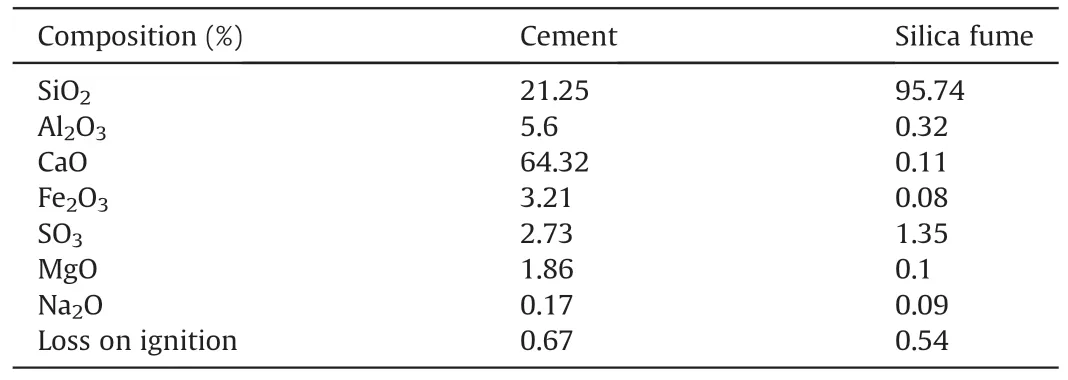
Table 1Chemical composition of cement and silica fume.

Table 2Mix proportion.

Table 3Mechanical properties of steel fiber.
Cylindrical specimens with a diameter of 47 mm and a height of 135 mm were casted for uniaxial compressive strength(UCS)tests.Both ends of the specimen were ground to ensure they are parallel to each other within the error tolerance.For the indirect tensile strength test,specimens of 50-mm diameter and 25-mm thickness were cast for each grout mix.For the direct shear test,cubic specimens(100 mm×100 mm×100 mm)were cast for each grout mix using plastic molds.Five specimens for each mix were cast for the direct shear test.The casted specimens were left for 24 h at room temperature in.Fig.2a illustrates an example of the cubic specimens.
2.2.Experimental set-up
An RMT-150C servo-controlled material testing machine was used for uniaxial compression,Brazilian,and direct shear tests.The machine is capable of applying maximum normal and shear loads of 1000 kN,and 500 kN,respectively.Four high-precision Linear Variable Differential Transformers (LVDTs) were used to monitor the normal and shear displacements (two for each displacement).The data acquisition system of the testing machine can automatically monitor and store the loads and displacements.The accuracy of the normal and shear loads/displacements were±1 N/0.01 mm.An axial force was applied to the specimens at a constant displacement rate of 0.003 mm/s to rupture the specimen.The experimental setup for uniaxial compression and Brazilian tests is shown in Fig.3.The experimental results of three specimens were averaged to determine the uniaxial compressive and tensile strengths of grout following the ISRM standards (Bieniawski and Bernede,1979).The determined UCS,tensile strength,elastic modulus of each test and the corresponding average values and standard deviations are detailed in Table 5.For the direct shear test,constant normal load (CNL) was applied for all grout mixes.The specimen was installed in the shear box,and one side of the box along the predefined shear plane was attached to the connector,and the other side of the shear box was connected with the shear load actuator.The configuration of the direct shear test is shown in Fig.3g.Then the normal load was applied at a low constant rate of 0.1 kN/s to ensure quasi-static deformation.When the prescribed constant load was reached,the normal and shear linear variable differential transformer (LVDT) was set to zero to monitor the normal displacement (dilation) and shear displacement.The shearing load was increased at a constant rate of 0.5 mm/min following the ISRM standard (ISRM,2007).After the test,the normal and shear load actuators were released,and the failure plane and the fiber distribution in the specimen were examined.Such a process was carried out on all specimens at five different normal stresses,i.e.,0.5 MPa,1 MPa,2 MPa,4 MPa,and 6 MPa,in order to acquire the shear strength envelope.

Fig.3.Test setup for uniaxial compression and Brazilian tests:(a)LVDT,(b)RMT-150C machine use for UCS,Brazilian,and direct shear test,(c)Specimen holder for Brazilian test,(d)Data acquisition system,(e) Specimen holder for uniaxial compression test,(f) Setup of the Brazilian test,and (g) Setup of the direct shear test.
2.3.Microscopic examination
Scanning electron microscopy(SEM)analysis was conducted to examine the influence of fiber geometry on the bond behaviour between fiber and the cement matrix using the Quanta 450 tungsten filament SEM device.SEM facilitates post-mortem examination of the failure crack pattern at the microscale.The failed specimens with wavy and straight fibers obtained from the uniaxial compression tests were used to examine the fiber-matrix interface bonding.The specimen preparation process for SEM is shown in Fig.4.The cross-section of the failed region of the specimens was prepared in 2 mm thick,10 mm long,and 10 mm wide to fit the SEM specimen chamber.The specimens were oven-dried for 24 h before SEM analysis.

Fig.4.Specimen preparation for SEM analysis.
2.4.Pullout test
Subsequently,a series of pullout tests were carried out on 15 mm-diameter rebar bolts (see Fig.5) with MR,SFM and SSF-1 grouts,respectively,subject to various confining pressures (0,0.5 and 1.0 MPa).The mechanical properties of the rebar bolt are listed in Table 4.A modified Hoek Cell was used to provide the constant confining pressure during the pullout test(see Fig.5).The Hoek Cell is 370 mm high and weighs 70 kg.It consists of a cell body that is 215 mm high with a cylindrical cavity of 70 mm diameter to accommodate a rubber sealing sleeve and pullout specimen.The rubber sealing sleeve is 195 mm high,10 mm thick,and with an inner diameter of 52 mm.The cell body is threaded at the outer ends at a length of 50 mm to fasten both ends with end caps.Two small holes are extruded to the cell body for fluid inlet,and the other is for air outlet.The cell body is 35 mm thick and can apply a confining pressure up to 50 MPa.The hydraulic ram is able to apply an axial load as high as 1500 kN with a maximum stroke of 75 mm.The data precision of the modified Hoek cell and hydraulic ram are both ±1 N.A long-stroke,high-precision (at accuracy of 0.01 mm)LVDT was fixed at the jack side to monitor the axial displacement.The whole pullout testing set-up is illustrated in Fig.6.The embedment length was 140 mm and the diameter of the grout was 50 mm.
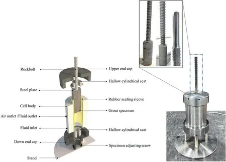
Fig.5.Detailed illustration of the triaxial cell for pullout test.The left illustrates the cross-section of the modified Hoek Cell,and the right shows the modified Hoek Cell in the laboratory containing the pullout specimen.The inset in the upper from left to right shows the specimen place in laboratory at room temperature,specimen after demolding and screwed section of the rockbolt.

Fig.6.Overall experimental system of the pullout test with confining pressure.
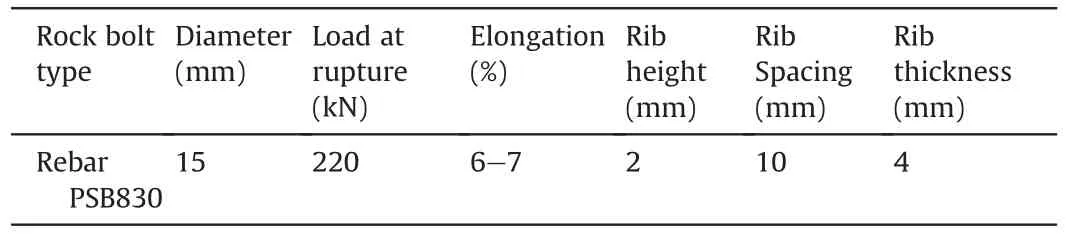
Table 4Mechanical properties of rebar bolt.
3.Results and analysis
3.1.Compression and tension
The stress-strain curves for MR,SFM,SSF-1,SSF-2,SSF-3,SWF-1,SWF-2,and SWF-3 resulted from uniaxial compression tests are shown in Fig.7.As expected,grout mix with 15%SF(SFM)achieved a higher UCS than plain grout (MR).Additionally,the grout with both SF and steel fiber regardless of the fiber geometry(SSF or SWF)improved the compressive strength of grout compared to SFM and MR.It was also noted that the incorporation of steel fiber improved the post crack behaviour of grout compared to MR and SFM in a way that the residual strength deteriorated more slowly.By contrast,MR and SFM exhibited typical brittle failure modes,which suggested a low energy absorption capacity.Table 5 shows the mean values of UCS,elastic modulus,and tensile strength of different grout mixes along with standard deviations.The grout strength could be increased by adding steel fiber and SF.By replacing 15%cement with SF,the UCS,elastic modulus,and tensile strength of grout could be increased by 15.3%,4%,and 12.4%,respectively.A further addition of 1.5% straight steel fiber in volume (SSF-3)increased the UCS,elastic modulus,tensile strength of the grout by 30%,65.4%,and 79%,respectively.By contrast,the addition of 1.5%wavy steel fiber in volume (SWF-3) increased the UCS,elastic modulus,tensile strength of the grout by 36.6%,73%,and 81.6%,respectively,compared to those strength parameters of MR.It was also noted that the grout mechanical properties could be increased by increasing the volume proportion of the steel fiber in the grout.This might be attributed to an increase in fiber volume proportion leading to the reduced average spacing between steel fibers in the cement matrix and hence improved load carrying capacity.It is noticeable that the increase in grout compressive strength by adding 0.5%fiber in the grout is marginal,whereas the addition of 1% and 1.5% fiber in volume significantly increased the grout strength.

Fig.7.Experimental results: (a) Failure modes after uniaxial compression tests (UCS),(b) Axial stress-strain data of UCS tests and (c) Failure modes after Brazilian tests.

Table 5Average uniaxial compressive and tensile strengths of grouts.
Plain cementitious materials are characterized by low strength and brittle material.Reinforcing cementitious matrix with fiber reduces the brittleness,and they are effective for crack minimization.Fig.7 shows the failure modes of grout specimens after uniaxial compression and Brazilian tests.A typical brittle failure mode was observed in the plain grout(MR)and grout with 15%SF(SFM)after uniaxial compression test(see Fig.7a).Multiple vertical cracks propagate along the direction of the applied load.On the other hand,the addition of steel fiber into the grout with different fiber volume reduced the brittleness and hindered crack propagation.The presence of randomly oriented short steel fiber in the cement matrix arrested micro-cracks and prevented them from propagation that might potentially lead to catastrophic failure.The increase in fiber volume from 0.5% to 1.5% with either straight or wavy fiber leads to less severe damage on the grout.The damage pattern in MR and SFM after indirect tensile test (see Fig.7c) is a wide crack in the middle of the specimen along the applied load direction.The crack in the specimen MR and SFM splits the specimen into two pieces.It is noteworthy that such a behaviour has not been observed in any FRG specimens.Although the FRG specimen failed with small cracks,the crack width varied with different volume proportions of steel fiber.
3.2.Shear behaviour
Direct shear tests were conducted on MR,SFM,SSF-1,SSF-2,SSF-3,SWF-1,SWF-2,and SWF-3 under different CNLs.The experimental results under different normal stresses are summarized in Table 6.It was found that grout shear strength could be increased by adding 15% SF in volume into the grout mix compared to MR grout.Furthermore,addition of both SF and steel fiber could considerably increase the grout shear strength further,and so does an increase in normal stress.The shear stress versus shear displacement of MR,SFM,SSF-3,and SWF-3 under five different normal stresses are shown in Fig.8.It could be further evidenced that both the peak and residual strengths of grout could be increased with the normal stress.SFM (see Fig.8b) increased the shear strength of the grout subjected to 0.5 MPa,1 MPa,4 MPa,and 6 MPa normal stresses by 10.4%,35.8%,19.0%,and 7%,respectively compared to plain cementitious grout,whereas such an effect was negligible under the normal stress of 2 MPa.As expected,addition of both SF and 1.5%steel fiber in volume into the grout significantly increased the shear strength.This could be evidenced by Fig.8c where the SSF-3 grout mix enhanced shear strength of the grout subjected to 0.5 MPa,1 MPa,2 MPa,4 MPa,and 6 MPa normal stresses by 46.3%,32.1%,39.6%,80.2%,and 23.8%,respectively compared to MR.Also,the SWF-3(see Fig.8d)grout enhanced the shear strength of the grout subjected to 0.5 MPa,1 MPa,2 MPa,4,MPa and 6 MPa normal stresses by 59.7%,37%,38.7%,65.8%,and 22.6%,respectively compared to MR.Fig.9 shows the shear stressshear displacement relationships of MR,SFM,SSF-3,and SWF-3 under various normal stresses of 0.5 MPa,2 MPa,and 6 MPa.After peak shear strengths,MR and SFM grouts lost their load-bearing capacity with a sudden drop in the shear stresses (see Fig.9).The peak shear strengths of MR and SFM,under 0.5 MPa normal stress were reached at shear displacements of 1.27 mm and 1.45 mm,respectively.On the other hand,the 1.5%fiber in volume enhanced the shear strength of grout,and the peak shear strength under 0.5 MPa normal stress for SSF-3 and SWF-3 occurred at the shear displacement of 1.80 mm and 1.85 mm,respectively(Fig.9a).Under 2 MPa normal stress(Fig.9b),peak shear strength of MR and SFM occurred at the same shear displacement of 2.18 mm.SWF-3 peak shear strength occurred at a larger shear displacement of 2.32 mm compared to MR and SFM.By contrast,peak strength of SSF-3 grout mix occurred at a smaller shear displacement of 1.53 mm.Under 6 MPa normal stress(Fig.9c),SSF-3 and SWF-3 peak shear strength occurred at a larger shear displacement than MR and SFM.The increase in shear strength of FRG is due to the fiber-matrix bonding,which helps to resist shear at the crack and sustain the load carrying capacity after peak strength.Higher residual strength in the post cracking stage was observed compared to MR and SFM.
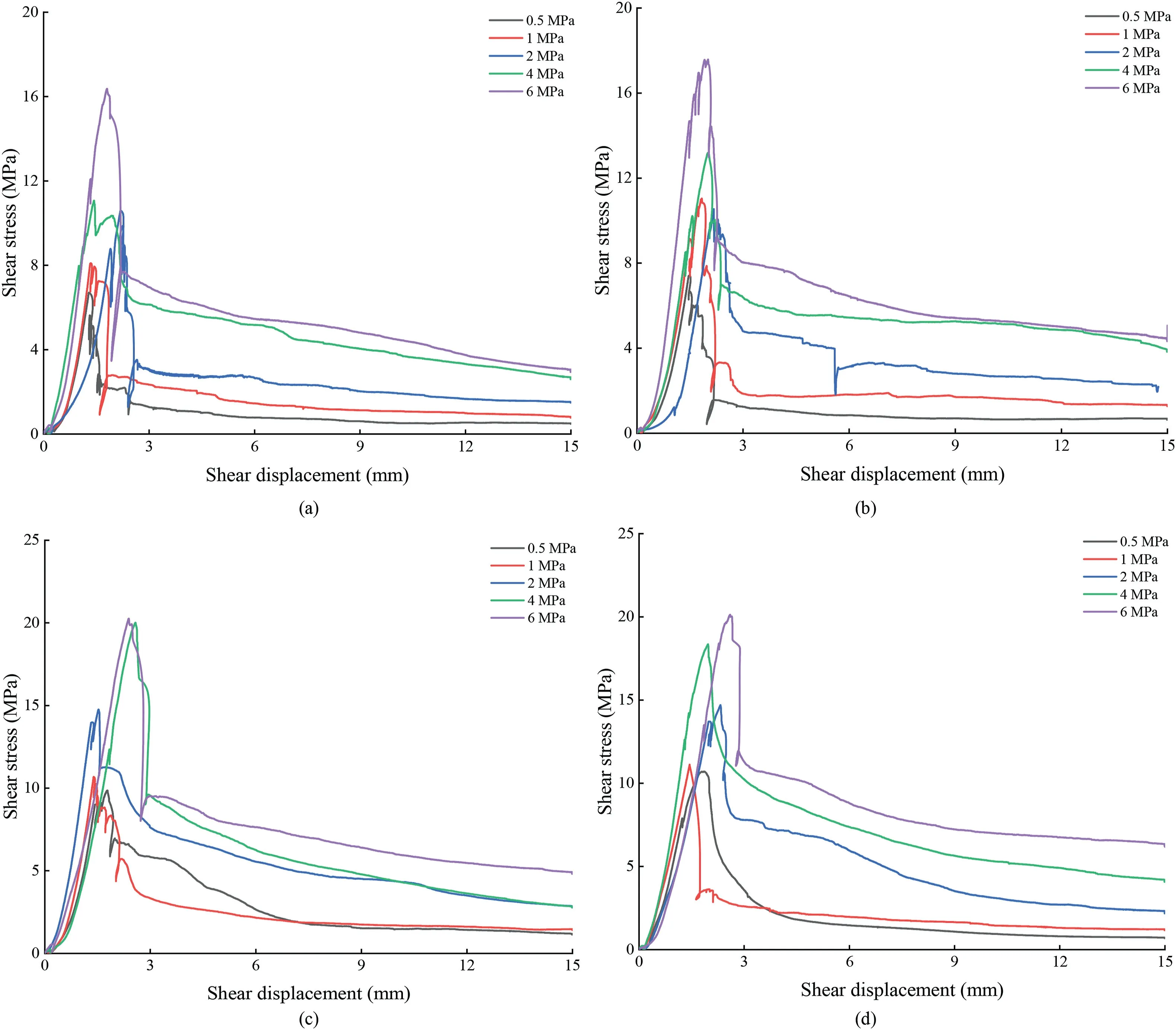
Fig.8.Shear stress versus shear displacement under different CNLs:(a)Plain grout(MR),(b)15%silica fume replacement of cement(SFM),(c)Straight fiber 1.5%fiber content(SSF-3),and (d) Wavy fiber 1.5% fiber content (SWF-3).

Fig.9.Comparison between shear strengths of MR,SFM,SSF-3 and SWF-3 under different CNLs of(a)0.5 MPa,(b)2 MPa,(c)6 MPa CNL,and(d)Peak dilation angles under different CNLs.

Table 6Direct shear test results under different CNLs.
The correlation between peak dilation angle and normal stress of all grout mix from direct shear tests is shown in Fig.9d.Grout peak dilation angle reduced with an increase in normal stress,and grout with higher UCS led to a higher dilation angle in the test,which was consistent with the findings by Moosavi and Bawden(2003).Such an observation might be attributed to the fact that under high normal stress conditions,shearing through of the asperity is more dominant than sliding along the asperity surface.After each test,the shear box was removed,and the failure plane was examined.The failure plane of MR,SFM,SSF-3,and SWF-3 under 6 MPa are shown in Fig.10.The SWF-1 grout mix attained the lowest shear strength,possibly due to the poor dispersion of SF or steel fiber in the grout leading to a weaker plane formed in the specimen.The shear stress-shear displacement curves of all mixes under the normal stress of 4 MPa are shown in Fig.11.We found that the increase in the fiber volume could increase the peak and residual shear strengths of the grout.The peak shear strengths of SSF were all higher than SWF under the same fiber proportions.For example,SSF-3 had a peak shear strength of roughly 20 MPa,which is around 3 MPa higher than that of SWF-3.The peak shear strengths of SSF-3 and SWF-3 were reached at larger peak shear displacements of 2.0 mm and 2.6 mm,respectively,compared to MR and SFM mixes.The increase in the residual strength might be attributed to the addition of steel fiber in the grout SSF-3 and SWF-3 leading to an increase in the distinct bond at the crack surface.As a result,the residual strengths of SSF-3 and SWF-3 were higher than that of MR and SFM.The zoom-in view of the fiber pullout after shear is shown in Fig.11b.The relationships between the shear strength and the applied normal stresses for various grouts resulted from the direct shear test are shown in Fig.12.The peak shear strength is found to be linearly proportional to the normal stress and the classic Mohr-Coulomb criterion is used to best fit the data:

Fig.11.Direct shear test results under 4 MPa normal stress: (a) Shear stress-shear displacement curves and (b) failed cubic samples of side length of 100 mm after direct shear.

Fig.12.Shear strength properties of grout samples with different fiber volume proportions (a) Peak shear strength versus normal stress and calculated cohesion and internal friction angle by the Mohr-Coulomb criteria,and (b) Comparison of cohesion and internal friction angle at different fiber volume proportions.
where τpis the shear stress,cis the cohesion of grout material,σnis the normal stress applied to the grout,and φ is the internal friction angle.
The cohesions and internal friction angles of various grout mixes are listed in Fig.12.SFM has a slightly higher cohesion (c) and internal friction angle(φ)than MR.Fig.12b shows that the cohesion grows with an increased fiber volume in the grout.Generally,SWF-1,SWF-2 and SWF-3 exhibited higher cohesions than SSF-1,SSF-2,and SSF-3 where the highest cohesion was observed for SWF-3.The value of internal friction angle was not significantly affected by silica fume since only 0.3°(less than 1% percentage error) difference between MR and SFM.The internal friction angle tended to increase with the fiber volume in the grout(Fig.12b)regardless of the fiber type;SSF-1 and SWF-1 displayed the lowest internal friction angles among SSF and SWF respectively.Possibly due to the shape difference between straight and wavy fibers,the internal friction angle of SWF-1 was substantially lower than that of SSF-1 whereas the cohesion of SWF-1 was considerably higher than that of SSF-1.The correlations between the grout residual strength and normal stress for various types of grout are shown in Fig.13.Similarly,the residual strength of each grout is in linear proportion to the normal stress.The residual friction angles of each grout mix are determined by best fitting to data which has the form:

Fig.13.Shear strength experimental results: (a) Residual shear strength versus normal stresses of all grout mixes (b) Effect of fiber shape on uniaxial compressive and tensile strength,and (c) Effect of fiber shape on peak shear strength under different normal stresses.
Where τris the shear stress,σnis the normal stress applied to the grout,and φris the residual friction angle.
The residual friction angles of different grout mixes are listed in Fig.13a.It could be concluded that the most important parameter representing the residual strength,residual friction angle,could be increased by adding the steel fiber where SWF-3 exhibits the highest residual friction angle.Specifically,adding 1%and 1.5%fiber content could significantly influence residual friction angle whereas the influence of 0.5% steel fiber on the residual friction angle is limited.
3.3.Effect of fiber volume proportion and geometry on the mechanical properties of FRG
The effects of fiber volume proportion and fiber geometry on the uniaxial compressive and tensile strengths of FRG are shown in Fig.13b and c.It was found that the wavy fiber could slightly increase the UCS of the grout compared to the grout with straight fiber.For the grout with 1% steel fiber in volume,the increase in UCS of the grout was 4.4% whereas for the grout with 1.5% steel fiber in volume,it was 5.1%.On the other hand,for the grout with 0.5% fiber in volume,UCS seems to be the same regardless of the fiber geometry.
By contrast,except for the grout with 0.5%steel fiber in volume where the wavy fiber could increase the grout tensile strength by 31.8%,only marginal increase in tensile strength was observed by changing the straight fiber to wavy fiber for other grout mixtures.For grout with 1%fiber in volume,the wavy fiber could increase the tensile strength of the grout by 3% whereas,for grout with 1.5%fiber in volume,such an increase was only 2%.Such an increase in both UCS and tensile strength could be attributed to the wavy shape of the fibers leading to a stronger bonding with cement-matrix.The effects of fiber geometry on the shear strengths of various types of grout are shown in Fig.13c.It could be found that such an influence is insignificant,which might be attributed to the orientation of the fiber at the predefined shear plane.
3.4.SEM observation
The failure plane of one specimen after the UCS test was scanned using SEM technique for analysing the micro scale bonding at the fiber to matrix interface.The images from SEM analysis are shown in Fig.14.It was found that the wavy fiber has a stronger bond with the matrix than straight fiber owing to its rougher surface geometry (see Fig.14a and b).It was also found that the bond at the interface of fiber and matrix could prevent the crack from propagation leading to the increased grout strength(see Fig.14c).Fig.14d shows that steel fiber arrested the micro-crack and hence stopped the crack from propagating to the other side of the steel fiber.

Fig.14.SEM analysis: (a) Wavy fiber-matrix interface,(b) Straight fiber-matrix interface,(c) Crack divergence,and (d) Crack bridging.
3.5.Pullout test data analysis
The load-displacement performance of rebar bolts with different grouts (MR,SFM and SSF-1) subject to various confining pressures are demonstrated in Fig.15.To avoid the effect of seating at the initial loading stage on the pullout results to the maximum extent,based on considerable trial-and-error tests,we prescribed a pre-force at 2 kN to tight the spacings among different components of the experimental system and re-set the values of loading and displacement before applying further loading.It is noted that regardless of the grout type,the axial load in the bolt would increase quickly or almost linearly before it reaches the peak load carrying capacity.Thereafter the axial load dropped significantly followed by a series of fluctuations in load at the residual level.It is noteworthy that the axial load fluctuated every 10 mm displacement at the residual stage.Such a behaviour might be attributed to the 10 mm rib spacing in the rebar bolt leading to form a 10 mm long grout ridge between two adjacent ribs.Once the rebar debonded from the grout,the rib tended to ride over the ridges resulting in an increase in the axial load until it moved close enough to the next trough to induce the grout crush resulting in a reduction in the axial load.This ‘slip and lock’ movement continued as the rebar being pulled out but the residual strength was gradually deteriorated because the number of ribs in the embedment section decreased during the test.One the other hand,the pullout tests with all three grouts at zero confining pressure condition were exceptional in a way that once the peak load carrying capacity was reached,there was negligible residual strength.Such a different behaviour might be related to the absence of the confinement to the rebar once the grout annulus fell apart after reaching the peak axial load.Without the confinement provided by the grout annulus,the rebar lost its load carrying capacity.

Fig.15.Pullout load-displacement curves for different grouts at various confining pressures (a) MR grout,(b) SFM grout,and (c) SSF-1 grout.
The comparisons between the load-displacement performance of the rebar bolts with different grouts at various confining pressures were illustrated in Fig.16.It could be apparently seen that the test with SSF-1 grout could achieve the highest load carry capacity of the rebar bolt during the full displacement followed by that with SFM grout and MR grout in sequence.As such,it could be concluded that the silica fume could increase the load carrying capacity of the rebar bolt compared to the conventional plain cementitious grout.Furthermore,the massive fibers in the grout could further increase the load carrying capacity of the rebar under axial loading by another significant extent.Such an observation could also be evidenced by the comparisons of the peak load carrying capacity of the rebar with different grouts seen in Table 7.The promising positive influence of the fibers on the load-displacement performance of the rebar under axial loading is attributed to the bridging effect of the fibers in the grout(especially the fibers oriented along the circular arches of the cylindrical grout annulus) leading to a closer radial crack than that in the grout without fibers(see Fig.17).It has been evidenced by quite a few past researchers (Hyett et al.,1995b;Kaiser et al.,1992;Li et al.,2017,2020) that the load carrying capacity of rock/cable bolts under axial loading could be influenced significantly by the radial crack in the grout.The closer crack or no crack would lead to a better integrity of the confinement to the rebar bolt resulting in a higher load carrying capacity.It could be seen that with the help of the fibers in the grout,the test samples with SSF-1 grout even remained intact after the pullout tests confirming that the fibers acted as an excellent bridge to prevent the grout annulus from radial crack (see Fig.17).

Fig.16.Comparisons between load-displacement performances of rebar with different grouts at various confining pressures (a) 0 MPa,(b) 0.5 MPa,and (c) 1 MPa.

Fig.17.Comparison between the failure modes after pullout tests with different grouts.
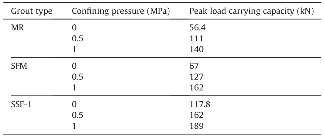
Table 7Peak load carrying capacity under different loading conditions.
It is noteworthy that the core interest of this study is the comparative analysis of the FRG performance in load carrying capacity of rock bolts.As opposed to the conventional parameters including embedment length,grout strength,type of rock bolt,borehole diameter and so on that have been extensively investigated in the past (Chen and Mitri,2005;Goris,1990;Hyett et al.,1995a;Reichert,1991;Stillborg,1984),the parameters of the interests in this study would focus on the fiber shape and fiber content in the FRG,both of which have not been sufficiently appreciated in the ground support community.Having said that,this research was conducted based on the hypothesis that the conventional parameters would influence the FRG encapsulated rock bolts in the same way that conventional grout does.For instance,an increase in the embedment length of FRG could significantly increase the contact area between the rock bolt and grout and consequently enhance the shear resistance during the slip of the rock bolt.On the other hand,it is noteworthy that the failure mechanism might vary once the embedment length is longer than the critical bond length.The rock bolt would rupture if the embedment length was too long.In this study,our core interests are on the bond strength at the rock bolt to grout interface,as well as how the presence of the fiber content affects such a bond strength.As such,we kept the embedment length of the grouted rock bolt to a low level of 140 mm in this study in order to restrict the failure at the bolt to grout interface.Additionally,we also believe that the critical bond length would be reduced if the rock bolt was grouted with FRG compared to that grouted with conventional grout.This could be attributed to the higher confinement to the rock bolt through the improved FRG integrity during the pullout.This is definitely another interesting topic that we can explore in the future.
4.Conclusions
The paper systematically investigated the effects of silica fume and steel fiber on the uniaxial compressive,indirect tensile,and direct shear strengths of the grout,and bearing capacity of fullygrouted rock bolts of different types of grout.The following conclusions are made:
(1) The experimental results showed that the 15% SF in volume and steel fiber could increase the grout strength.The SSF-3 and SWF-3 exhibited higher UCS,tensile and shear strengths than SFM and MR.
(2) The uniaxial compression and indirect tensile tests showed that the grout failure mode could be changed from brittle to ductile by adding steel fiber in the grout.
(3) The addition of both steel fiber and SF could increase the peak shear strength and residual shear strength of grout.Steel fiber,SF,and fiber volume proportion directly affected the mechanical properties of the grout in a way that an increase in the fiber content could increase the grout compressive strength,tensile strength and shear strength.
(4) The more integrated bonding between the steel fiber and grout annulus could be evidenced by scanning electron microscopy confirming that the fiber could prevent the crack from propagating in the grout.
Therefore,it is safe to draw the conclusion that FRG could lead to a higher compressive,shear,and tensile strengths compared to the conventional grout.Additionally,the comparison between the axial load-displacement performance of rebar with MR,SFM and SSF-1 grouts confirmed that the presence of fiber in the grout could improve the load carrying capacity of the rock bolt significantly.Thus,the rock bolting system with fiber-reinforced grout can be a potential candidate for the strong support required in the deep underground engineering projects.If the conventional grout is unable to meet the demand of the load capacity in the field especially where high in-situ stress is expected,fiber-reinforced grout should be considered as a substitute for improving the load carrying capacity of the rock bolt as evidenced by the research findings in this paper.It should also be noted that a standard for rock bolt installation with fiber-reinforced grout should later be developed to optimize the fiber orientation and distribution in the grout to maximize the grout strength and integrity.Furthermore,a suitable installation rig should be manufactured to accommodate the fiber contents in the grout.In the current study,fully grouted rock bolts were pullout under static conditions whereas dynamic loadings are commonly encountered in deep underground mining/excavation.Therefore,it is suggested that the performance of rock bolts with fiber-reinforced grouts under typical dynamic loadings should be examined in the near future.
Declaration of competing interest
The authors declare that they have no known competing financial interests or personal relationships that could have appeared to influence the work reported in this paper.
杂志排行

Journal of Rock Mechanics and Geotechnical Engineering的其它文章
- Determination of uncertainties of geomechanical parameters of metamorphic rocks using petrographic analyses
- Evaluation of excavation damaged zones (EDZs) in Horonobe Underground Research Laboratory (URL)
- On the calibration of a shear stress criterion for rock joints to represent the full stress-strain profile
- Effect of dynamic loading orientation on fracture properties of surrounding rocks in twin tunnels
- Experimental study on the influences of cutter geometry and material on scraper wear during shield TBM tunnelling in abrasive sandy ground
- Effect of fracture fluid flowback on shale microfractures using CT scanning