Ambiguity function analysis and side peaks suppression of Link16 signal based passive radar
2024-01-17BAILuyangWANGJunandCHENXiaoling
BAI Luyang, WANG Jun, and CHEN Xiaoling
National Key Laboratory of Radar Signal Processing, Xidian University, Xi’an 710071, China
Abstract: Link16 data link is the communication standard of the joint tactical information distribution system (JTIDS) used by the U.S.military and North Atlantic Treaty Organization, which is applied as the opportunistic illuminator for passive radar in this paper.The time-domain expression of the Link16 signal is established, and its ambiguity function expression is derived.The timedelay dimension and Doppler dimension side peaks of which lead to the appearance of the false target during target detection.To solve the problem, the time-delay dimension and Doppler dimension side peaks suppression methods are proposed.For the problem that the conventional mismatched filter (MMF) cannot suppress the time-delay dimension side peaks, a neighborhood MMF (NMMF) is proposed.Experimental results demonstrate the effectiveness of the proposed methods.
Keywords: passive radar, ambiguity function, Link16, mismatched filter (MMF).
1.Introduction
Passive radar is a bistatic/multistatic radar with separate transmitters and receivers, which detects passively by receiving the signal of the opportunistic illuminators reflected by the target.It has the advantages of strong concealment, low cost, and no electromagnetic pollution.Passive radar based on frequency modulation (FM) radio[1-5], digital radio [6-8], analog television (ATV)[9-11], digital television [12-18], mobile communication [19-23], and other civil illuminators has been widely studied in recent years.However, in the battlefield environment such as ocean and desert, which is far away from densely populated areas, the passive radar is facing the problem of lacking civilian illuminators, so it cannot be used in these battlefield environments.In modern war, to realize information exchange and environment perception functions such as communication and detection,there are a large number of military illuminators on the battlefield.Therefore, the study of passive radar based on military illuminators has a great applicable value.
Military illuminators generally include radar, tactical data link (TDL), tactical air navigation system (TACAN),and others.TDL, also known as Link in North Atlantic Treaty Organization (NATO), is used to transmit machinereadable tactical digital information as a standard communication link [24].Link16 data link is the communication standard of the joint tactical information distribution system (JTIDS) used by the U.S.military and NATO,which is applied to the communication, navigation, and identification between aircraft, warship, and other weapon platforms.Meanwhile, Link16 is one of the most widely used TDL in the world, which makes it possible to use Link16 signal as the illuminators of passive radar in battlefield environment.However, the current research on Link16 data link is only limited to the field of communication, and there is no research on Link16 signal based passive radar.
Unlike active radar transmitting a designed waveform,passive radar uses non-cooperative opportunistic illuminators to detect targets.When the ambiguity function of the signal transmitted by opportunistic illuminators is not ideal, that is, the ambiguity function is not near thumbtack, these ambiguity ranges and Doppler side peaks will be detected as targets and degrade the target detection performance.Therefore, the side peaks of the ambiguity function must be suppressed before target detection.Side peak suppression methods in existing studies can be divided into two categories [25].The first category suppresses the side peaks by removing or preprocessing the guard interval (GI) and cyclic prefix (CP) in the signal frame.This method needs to know the frame structure of the signal and is mostly used for digitally modulated signals, such as Wi-Fi [26-29] and digital television[13,30-32].The second method is based on mismatched filter (MMF).MMF is relative to matched filter (MF),which was first used to improve the phase-coded radar waveforms’ side lobe structure [33].In [11], the author applied the MMF method to suppress the time-delay dimension side peaks of ATV-based passive radar for the first time.MMF achieves the purpose of side peak suppression by establishing a cost function and solving the optimal MMF factor and then performing mismatch processing on the reference signal.This method does not need to know the structure of the signal accurately, and only needs to know the position of the side peaks on the range-Doppler surface, and it is mainly applied to analog modulated signals.At present, there are also many studies on improving the cost function to obtain better side peaks suppression performance [15,34-36].
In this paper, Link16 signal is used as the illuminator of opportunity for passive radar, which is modeled mathematically and constructed time domain expression.Then,according to its definition, the ambiguity function of Link16 signal is deduced and the correctness is verified by simulation results.Subsequently, a neighborhood MMF (NMMF) algorithm is proposed to suppress the time-delay dimension side peaks, and this paper proposes a method of removing Doppler dimension side peaks.
The structure of this paper is organized as follows.In Section 2, the signal structure of Link16 is introduced and its time domain expression is established.In Section 3,the ambiguity function of Link16 signal is derived, and the cause of time-delay dimension and Doppler dimension side peaks is analyzed.In Section 4, the method of suppressing the side peaks is proposed.Finally, Section 5 presents the conclusions.
2.Structure of Link16 signal
Link16 data link is composed of J series message standard, JTIDS waveform, and time division multiple access(TDMA) protocol.In detail, the J series message is defined by the U.S.standard MIL-STD-6016 or NATO standard STANAG5516 and STANAG5616, which is the baseband information transmitted by the Link16 data link.JTIDS waveform is the transmitting signal which is suitable for transmission and strong anti-interference converted by JTIDS unit (JU) according to J series messages.TDMA protocol is used to control user access.
Take the single network structure as an example, the time slot division of Link16 is shown in Fig.1.The TDMA protocol divides a 24-hour day into 112.5 epochs,and each epoch is 12.8 min in duration; each epoch is divided into 64 frames, and each frame is 12 s in duration.Each frame is further divided into 1 536 time slots,each one of which is 7.812 5 ms in duration.The time slot is the basic unit of access to the Link16 network.

Fig.1 Diagram of Link16 time slot division
In a time slot, according to different data pulse formats,it can be divided into four packaging structures: standard double pulse (STDP), packed-2 single pulse (P2SP),packed-2 double pulse (P2DP), and packed-4 single pulse(P4SP).In order to ensure the strongest anti-interference performance, Link16 system usually uses STDP package,and its structure is shown in Fig.2.Therefore, this paper mainly studies the Link16 signal using STDP packaging structure.

Fig.2 STDP package structure
As shown in Fig.3, after receiving the J series messages generated by the Link16 unit, JU uses cyclic redundancy check (CRC) codes, reed-solomon (R-S) codes,interweave, cyclic code shift keying (CCSK) codes, codeword encryption, minimum shift keying (MSK) modulation, and frequency hopping, adding synchronous symbol and header to generate JTIDS waveform, with strong anti-interference capacity.Then package the waveform according to STDP package structure to generate the transmission signal.
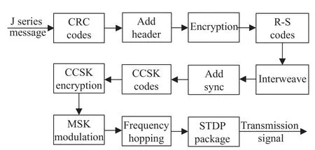
Fig.3 Transmission signal generation process
It should be noted that CCSK is applied to the 5-bit interleaved symbols of the R-S codewords.Each 5-bit symbol is represented by a 32-bit sequence.The bits of this sequence are called chips to avoid confusion.These 32-chip sequences are derived by shifting an arbitrary starting sequence number left one place each time, and each 5-bit interleaved symbol points to a specific chipping sequence.Since the 5-bit symbol’s binary value can vary from 0 to 31, there are 32 unique chipping sequencesS0toS31.
Then, the encrypted CCSK codeword is modulated by MSK with a bit rate ofRb=5 Mb/s to obtain a single or double pulse symbol package as shown in Fig.4, and the width of each MSK symbol isTB=0.2 μs.Therefore, the length of 32 MSK symbols is 32TB= 6.4 μs.In Fig.4,Tpis the pulse repetition period, andTpdis the pulse width.
MSK modulation is a special frequency shift keying(FSK) modulation.Compared with 2FSK signal, MSK signal has the advantages of continuous phase, minimum bandwidth, constant envelope, and strictly orthogonal.The modulation diagram is shown in Fig.5, whereakis the symbol to be encoded,bkis the symbol after differential encoding,pkandqkare the symbols after serial to parallel conversion, andfcis the carrier frequency.

Fig.4 Diagram of double and single pulse

Fig.5 Principle diagram of MSK quadrature modulation
Using orthogonal representation, the signal of thekth(k= 0,1,···,31) symbol modulated by MSK can be expressed as
wherepk= ±1 andqk= ±1 are serial to parallel converted symbols;ωcis the angular frequency of carrier.
The baseband complex envelope of theith pulse after MSK modulation is
And the signal of the valid portion in a time slot of the STDP package (remove jitter and propagation) can be expressed as
whereTp= 13 μs;Tpd= 6.4 μs; Δfiis the carrier frequency offset of theith pulse compared to the first pulse.It needs to be clear that the pulses in the STDP package structure appear in pairs, that is, the same group of 32 MSK symbols are transmitted with two pulses with different carrier frequencies.Thus, there ism2i-1=m2i(i=0,1,···,128).
Considering the portion of jitter and propagation, the Link16 signal withNtime slots can be expressed as
whereTs,Tj, andTdare the length of time slot, the length of jitter and the length of valid portion, andss,nis the signal transmitted in thenth time slot.SetTpras the length of propagation, and the STDP package structure specifies thatTs= 7.812 5 ms,Td= 3.354 ms, andTj+Tpr=4.458 5 ms.In order to facilitate analysis without losing generality, this paper setsTj= 2 ms andTpr= 2.458 5 ms.
Fig.6 and Fig.7 respectively show the time waveform and spectrum of the Link16 signal with 16 time slots which lasts for 0.125 s.
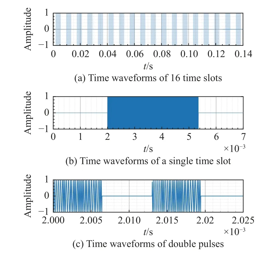
Fig.6 Time waveform of Link16 signal
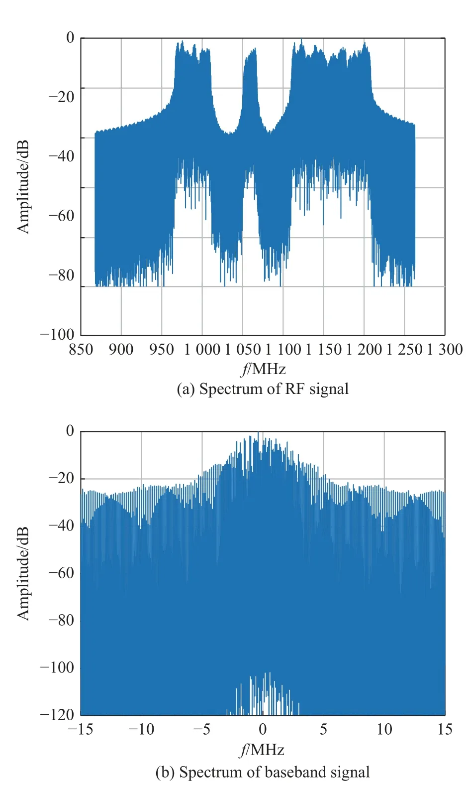
Fig.7 Spectrum of Link16 signal
Fig.6, from top to bottom, respectively shows the time waveforms of 16 time slots, a single time slot and the double pulses.And the variable carrier frequency with no phase discontinuities can be observed, which is the basic feature of MSK modulation.
Fig.7(a) is the spectrum of Link16 RF signal,which shows it works in frequency hopping between 960 MHz to 1 215 MHz, and Fig.7(b) is the spectrum of the Link16 baseband signal which down-converts the RF signal according to hopping patterns.It can be seen that multiple discrete spectral lines are attached to the MSK signal power spectrum [37], which is caused by the truncation of the MSK signal by multiple pulses.
3.Ambiguity function analysis
The ambiguity function of the radar signal [38] is defined as
whereτis the time delay;fdis the Doppler shift;u(t) is the complex envelope of Link16 signal, which down-converts the RF signal according to hopping patterns; (·)*represents complex conjugate operation.Fig.8 shows the ambiguity function of the Link16 signal with 16 time slots generated by the simulation in Section 1, with 0 ms ≤τ≤ 0.2 ms and -2 000 Hz ≤fd≤ 2 000 Hz.It can be seen from Fig.8 that the ambiguity function of Link16 signal is composed of a main peak and a lot of side peaks which almost cover the whole delay-Doppler plane.In order to facilitate the analysis, the side peaks are divided into timedelay dimension side peaks and Doppler dimension side peaks, that is, one of the variablesτorfdin χ(τ,fd) is taken as a fixed value, and the other is taken as a variable for analysis.Whenfdis fixed, it is the time-delay dimension of the ambiguity function.Fig.8(b) shows the zero Doppler cut χ(τ, 0) whenfd= 0 Hz.Whenτis fixed, it is the Doppler dimension of the ambiguity function.Fig.8(c) shows the zero delay cut χ(0,fd) whenτ= 0.
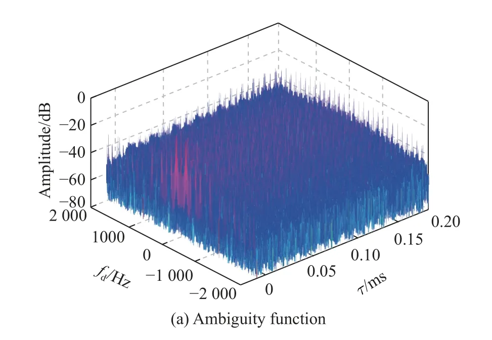
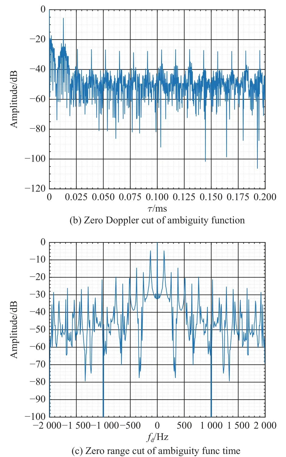
Fig.8 Ambiguity function of Link16 signal
To analyze the ambiguity function of Link16 signal,combining (4) and (5), we can get
Lett–nTs–Tj=t1, then (6) can be written as
where the integral term represents the cross-ambiguity function of thenth time slot and themth time slot,expressed by χs,nm.
Then he touched the youth, the girl, the sweep, the clown, the Mayor, and the Mayoress with his little stick, and they were all free again, and ran away home as if a fire were burning behind them; and their flight, as you may imagine, gave rise to renewed merriment
Letn–m=kin (7), and use the double summation formula [39] as follows:
then (7) can be rewritten as
Perform the following summation of series:
Then substitute the sum result in (10) into (9), we get
3.1 Cause of time-delay dimension side peak
In order to analyze the time-delay dimension of ambiguity function, letfd= 0 Hz in (11) and apply the limit
Then, we get
Because the information transmitted by each time slot is random, χs,nmin (7) has the following properties:
By applying the properties in (14), (13) can be simplified as
It can be seen from (15) that the time-delay dimension of Link16 signal ambiguity function is equal to the superposition of autocorrelation of each time slot.χs,0(τ, 0)is analyzed below.
Substituting (16) into (5) and lettingfd= 0 Hz, we get
Lett′ =t–iTp–Tj, then (17) can be written as
where the integral term in (18) represents the cross-correlation between theith MSK modulated pulse and thelth MSK modulated pulse, expressed by χil.Because the pulse width isTpd, the width of χil(τ, 0) is approximately equal to 2Tpd.And becauseTp> 2Tpd, each χildoes not overlap afterTpintegral multiple translation in time domain.To sum up, it is a simple superposition of crosscorrelation between single MSK modulated pulses after time-domain translation.
Because the baseband symbols modulated by MSK are random, and the same group of symbols in STDP package use two pulses for transmission,χilhas the following approximate relationship:
Leti–l=n, then fori,l∈[0,257], there are 258 combinations that makei–l= 0, that is,i=l.There are 2×(258–1)=514 combinations that make |i–l| = 1, of which 258 combinations ofiandlsatisfy the condition that
wherep=0,1,···,128.
By analogy, (18) can be rewritten as follows:
If only the part ofτ≥ 0 is considered, then (20) can be simplified as
And the ambiguity function of MSK modulation signal [40] is
It can be seen from (22) that χp(τ, 0) has a peak value atτ= 0.χv(τ, 0) and χp(τ, 0) have the same envelope, but the amplitude of χv(τ, 0) is much lower than χp(τ, 0).Therefore, the three terms in (21) satisfy
To sum up, in the zero Doppler cut, χ(τ, 0) has a peak atτ= 0, and side peaks appear atτ=nTp(n= 1, 2, ···)withTpas the period.The position where the first side peak appears isτ=Tp, and its amplitude is the largest compared with other side peaks.
3.2 Cause of Doppler dimension side peak
In order to analyze the Doppler dimension of ambiguity function, letτ= 0 in (11) and we can get
Ignore the phase term in (24) and applying the properties in (14), (24) can be simplified to
In (25), the term sin(πfdNTs)/sin(πfdTs) has a peak value atfd=n/Ts(nis an integer), and it has the zero point atfd=k/ (NTs) (kis a non-zero integer).It can be seen that the Doppler dimensional envelope of Link16 signal ambiguity function is equal to χs,0(0,fd), and the interior is filled with sin(πfdNTs)/sin(πfdTs).Next,χs,0(0,fd) is analyzed.
As in the previous section, taking the first time slot as an example, setN= 1 in (4), then substitute (16) into (5),and setτ= 0, we can get
Similar to the above analysis method, (26) can be further written as
In (27), the term sinc(32TBπfd) takes the peak value atfd= 0 Hz, and it takes the first zero point atfd= ±1/(32TB) =±156 250 Hz.And in the range of Doppler frequency shift-2 000 Hz ≤fd≤ 2 000 Hz, the term sinc(32TBπfd) ≈ 1,thus
It can be seen from (28) that χs,0(0,fd) takes the peak value atfd= 0 Hz, and takes the zero point atfd=k/(258Tp),kis the non-zero integer.Fig.9 shows the curve in Fig.8(c) where the zero range cut is normalized but without decibels, the dashed line is the envelope of sin((πfdNTs)/s)in(π(fdTs),) and its analytic formula is sin258πfdTp/sinπfdTp.The first side peak of χ(0,fd)is located atfd= ±1/Ts= ±128 Hz, which has the largest amplitude compared with other side peaks.The zero point is located atfd= ±298 Hz, ±596 Hz, ±894 Hz, and ±1 193 Hz, which is also the reason for the formation of several zero lines in Fig.8(c).
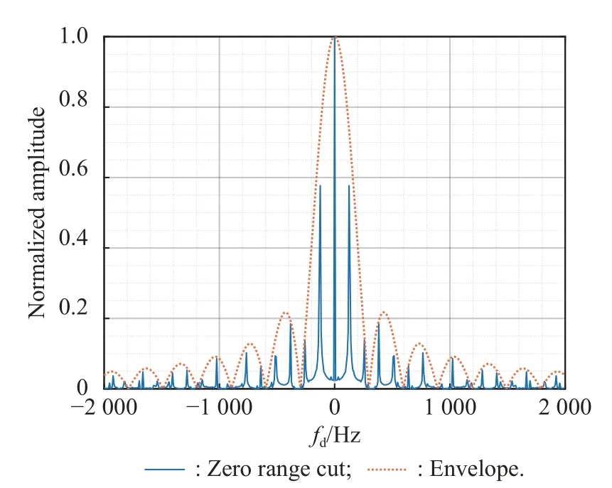
Fig.9 Zero range cut of ambiguity function
4.Side peaks suppression method
From the analysis and simulation results in Section 3, it can be seen that there are many side peaks with high amplitude in the ambiguity function of Link16 signal,which will lead to the appearance of false targets in target detection, so it is necessary to suppress the side peaks.On the basis of Section 3, this section will propose a method to suppress side peak of Link16 signal.
It can be seen from the analysis in Subsection 3.1 that the periodic pulse structure of Link16 signal in time domain causes side peaks with high amplitude in timedelay dimension.In analog television (ATV) based passive radar, Wang et al.[11] used the MMF algorithm in binary phase-coded radar to suppress the time-delay dimension side peaks caused by the periodicity of 64 μs continuous line signal which transmits ATV picture.However, the Link16 signal used in this paper is a discrete signal truncated by pulse in time domain, and the two adjacent time slots have strong correlation.The cost function in [11] only restricts the energy at the side peak,and cannot effectively suppress the side peak of Link16 signal.Therefore, in this paper, the improved NMMF algorithm is proposed to suppress the side peaks.
NMMF suppresses the energy in the side peak and its neighborhood by constructing a cost function and controls the output signal-to-noise ratio loss caused by mismatch.The cost function can be written as
wherewmis∈CL×1is the NMMF factor to be solved;w=[s(0),s(1), ···,s(l-1)]Tis the MF factor;cdis a weighted factor andcd> 0;dis the position of time-delay dimension side peak;U(d,δ) is theδneighborhood of pointd,andU(d,δ) = {k∈Z|d-δ≤ k ≤d+δ};s(k) = [s(k),s(k+1), ···,s(k+L-1)]T, andLis the length of Link16 signal.
The Hessian matrix of the cost functionJis
whereILis anL×Lidentity matrix.It can be seen thatEis a positive semi-definite matrix whencd> 0.From the second-order necessary and sufficient condition of convex function, we knowJis a convex function.When ∇J=0, the NMMF factor obtains the optimal solution,where
Therefore, the optimal solution of the NMMF factor is
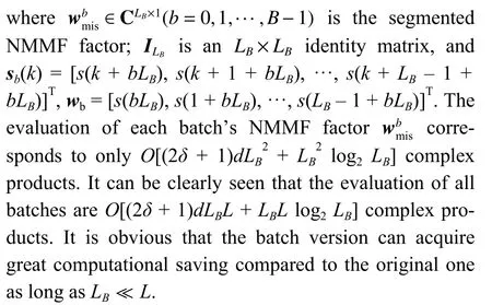
In order to obtain higher integration gain, the passive radar often has a longer coherent integration time, which makes the signal lengthLvery large (tens of thousands or more).It can be seen from (32) that the inverse ofL-order matrix is required when calculating the NMMF factor,and corresponding toO[(2δ+ 1)dL2+L2log2L] complex products.This will cost huge computing resources, and it is difficult to achieve.In order to reduce the computation burden, the batch version of the NMMF algorithm is proposed next.
The batch version algorithm divides the NMMF factor intoBsegments, each segment’s length isLB, and satisfiesL=BLB, which can be expressed asAnd the optimal solution of each segment NMMF factor is
According to the analysis of Subsection 3.1, letd=mTpfs(m= 1, 2, ···, 15) in (33), and the simulation results are shown in Fig.10.The blue solid line shows the zero Doppler cut after suppressing the side peaks using NMMF algorithm, the green dotted line is the result of using the MMF algorithm in [11], and the red dashed line is the result of MF.It can be clearly seen that when the NMMF algorithm is used to suppress the side peaks, the amplitude of the first side peak decreases by 13.69 dB,while the amplitudes of the other side peaks are below-25 dB.The result of the MMF algorithm in [11] is similar to MF, which cannot effectively suppress the timedelay dimension side peaks.
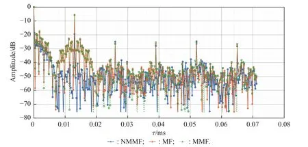
Fig.10 Zero Doppler cut result of NMMF
From the analysis of Subsection 3.2, it is known that the Doppler side peaks are caused by the pulse structure of the time slot.In order to suppress the Doppler side peak, the jitter and propagation corresponding to the NMMF factor and Link16 signal need to be removed, and then the remaining effective parts of the time slot need to be spliced together.After the above processing, the Doppler dimension side peaks can be eliminated.The result is shown in Fig.11.
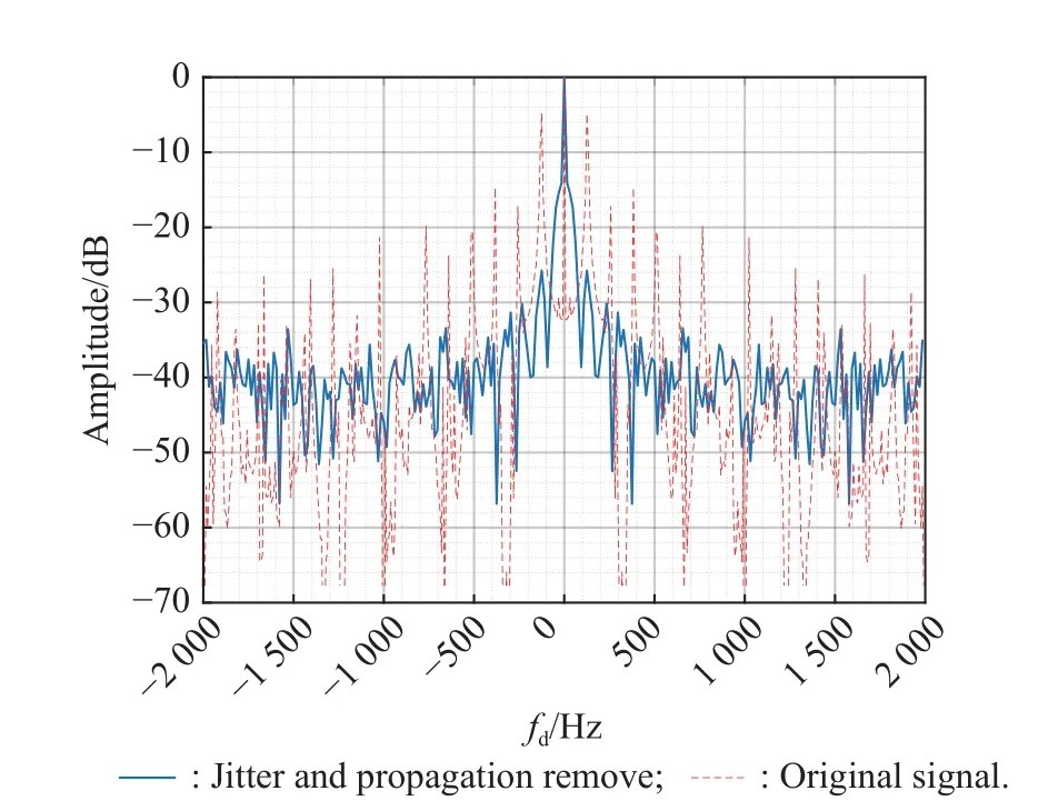
Fig.11 Zero range cut after removing jitter and propagation
Compared with the unremoved original signal, the amplitude of the first side peak in Doppler dimension has decreased by 20.95 dB, and the side peaks in the other positions are below -25.73 dB.
To sum up, the side peaks suppression method of Link16 signal ambiguity function is shown in Fig.12,and the ambiguity function after side peaks suppression is shown in Fig.13.
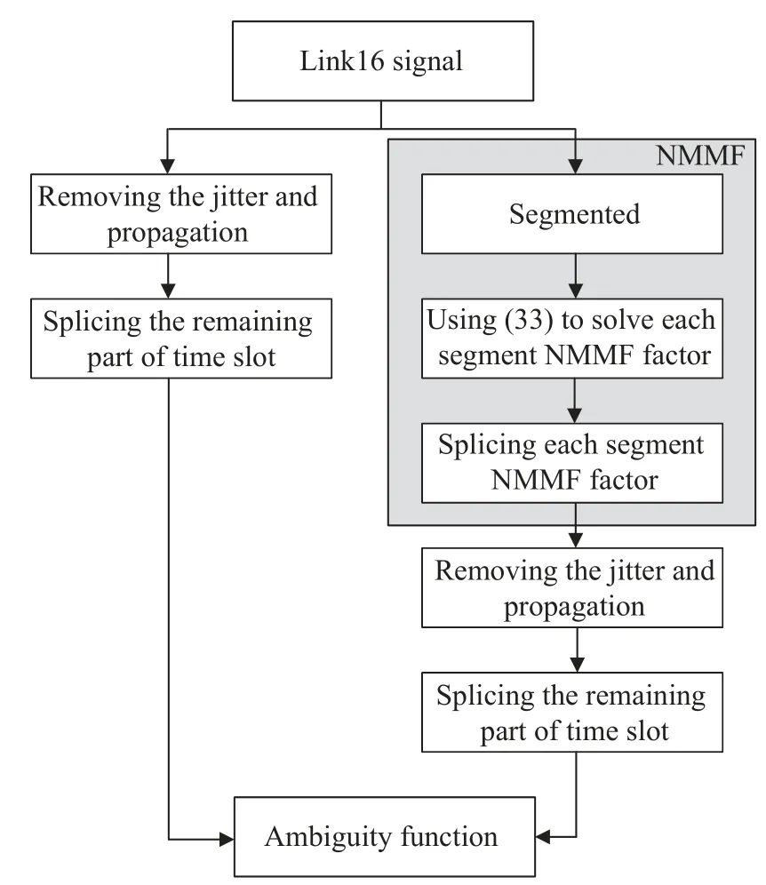
Fig.12 Flowchart of side peaks suppression method

Fig.13 Ambiguity function after side peaks suppression
5.Conclusions
This paper discusses the possibility of using Link16 signal as the opportunity illuminator of passive radar to detect targets.Firstly, the structure of Link16 signal is analyzed in detail, and the time domain expression of Link16 signal is given.Then, the ambiguity function expression of Link16 signal is deduced, and the causes of time-delay and Doppler dimension side peaks are analyzed with the simulation results.Subsequently, according to the causes of the side peaks, the methods of suppressing time-delay and Doppler dimension side peak are proposed, in which the NMMF algorithm is proposed when suppressing the time-delay dimension side peaks.The experimental results show that the proposed algorithm can effectively suppress the side peaks, which provides a theoretical basis for Link16 based passive radar.
杂志排行
Journal of Systems Engineering and Electronics的其它文章
- Two-layer formation-containment fault-tolerant control of fixed-wing UAV swarm for dynamic target tracking
- Role-based Bayesian decision framework for autonomous unmanned systems
- Nonlinear direct data-driven control for UAV formation flight system
- Minimum-energy leader-following formation of distributed multiagent systems with communication constraints
- A survey on joint-operation application for unmanned swarm formations under a complex confrontation environment
- Multicriteria game approach to air-to-air combat tactical decisions for multiple UAVs
