An image mosaic technique with non-overlapping regions based on microscopic vision in precision assembly
2024-01-08YaweiLiXiaodongWangTaoWangandYiLuo
Yawei Li, Xiaodong Wang,,2 Tao Wang, and Yi Luo,2,a)
AFFILIATIONS
1 Key Laboratory for Micro/Nano Technology and System of Liaoning Province,Dalian University of Technology,Dalian 116024,China
2Key Laboratory for Precision and Non-Traditional Machining of Ministry of Education,Dalian University of Technology,Dalian 116024,China
ABSTRACT Microscopic vision has been widely applied in precision assembly.To achieve sufficientl high resolution in measurements for precision assembly when the sizes of the parts involved exceed the fiel of view of the vision system,an image mosaic technique must be used.In this paper,a method for constructing an image mosaic with non-overlapping areas with enhanced efficienc is proposed.First,an image mosaic model for the part is created using a geometric model of the measurement system installed on a X-Y-Z precision stages with high repeatability,and a path for image acquisition is established.Second,images are captured along the same path for a specifie calibration plate,and an entire image is formed based on the given model.The measurement results obtained from the specifie calibration plate are utilized to identify mosaic errors and apply compensation for the part requiring measurement.Experimental results show that the maximum error is less than 4 μm for a camera with pixel equivalent 2.46 μm,thereby demonstrating the accuracy of the proposed method.This image mosaic technique with non-overlapping regions can simplify image acquisition and reduce the workload involved in constructing an image mosaic.
KEYWORDS Image mosaic,Microscopic vision,Visual measurement,Precision assembly
I.INTRODUCTION
In precision assembly,a microscopic vision system is typically used for the alignment of parts and is very important for ensuring product quality and improving production efficiency1–4At the same time,it can also be used for measurement of parts during inspection and for selection during assembly.5,6
In visual measurement,if the part being measured is large and the vision system has a wide fiel of view,it is difficul to obtain sufficientl high-resolution images to enable precise measurements.Therefore,the fiel of view of the vision system should be small in order to acquire an accurate image of the part being tested.Consequently,it is common to capture different parts of an image several times and then use an image mosaic method to merge partial images to obtain the entire image.7,8Thus,the image mosaic technique can be used to balance accuracy and fiel of view for precise visual measurements.
Generally,image mosaic algorithms use image registration to detect overlapping areas between two partial images,and the entire image is then acquired via image fusion.Common image registration algorithms include the scale-invariant feature transform(SIFT)algorithm,the speeded up robust features (SURF) algorithm,and the features from accelerated segment test(FAST)algorithm.Image fusion is typically achieved using the weighted average method.9
Image mosaic methods have been used for high-precision industrial visual detection.Fenget al.10improved the efficienc of image registration by narrowing the matching region and using a local signal-intensity ratio algorithm to perform feature matching.They then applied the random sample consensus (RANSAC)method to eliminate mismatching points.Finally,they used Poisson fusion to fuse images and implement online detection of inertial confinemen fusion terminal optical elements.Caiet al.11used edge detection to segment the subregions with the most obvious gray gradient change in overlapping regions and then applied the SIFT algorithm for image registration and conducted image fusion based on a sigmoid function weight.They applied this approach to obtain an image mosaic of the inner wall of a gun barrel.Songet al.12used an image mosaic method to detect an antenna circuit.The angle between theXandYaxes of a two-dimensional(2D)moving platform was calibrated using a calibration plate.A camera collected images with overlapping areas through a 2D moving platform,and the grating ruler recorded the position information of the moving platform simultaneously.The pixels of the mosaic image were then indexed to a specifi local image to obtain the gray value of the pixel by bilinear interpolation.Wanget al.13used the SIFT algorithm for image registration and realized an image mosaic of an entire groove structure during femtosecond laser processing.Zhouet al.14used the SIFT algorithm for image registration,utilizing slope probability measurement and the RANSAC algorithm to eliminate error-matching points.The weighted average method was used for image fusion in the process of inspecting surface defects of steel rotary parts.Caiet al.15used the histogram of oriented gradient(HOG)algorithm for image registration of tire molds and an averaging image fusion method to realize image fusion.
Image mosaic methods have also been used for microscopic visual measurements.Leiet al.16applied white-light interferometry to measure the microstructure of a microelectromechanical system (MEMS),using the features of gradient and corner points to establish an evaluation algorithm in an overlapping area of two adjacent images,register the two images,and establish a transformation model for them to realize the image mosaic.Liuet al.17proposed a feature-based multicycle image stitching algorithm for the evaluation of surface defects in large fin optics,categorizing the overlapping areas by the features they contained,stitching different types of overlapping areas in different ways,and finall obtaining a full aperture image.In addition,an image mosaic method has been used to splice the 3D data obtained from different scenes in largescale 3D topographic measurements using the overlapping areas of local data point clouds for 3D point cloud registration,converting local data point clouds to the same coordinate system,and then obtaining a stereo image of a part.18–20
However,most algorithms require overlapping areas of the subimages,and rely on image registration and fusion to obtain the complete image.Despite their usefulness,these processes are prone to false matches and have a heavy computational load,leading to lower efficienc and potential mosaic gaps.Meanwhile,precision stages with high repeatability and a camera with high resolution,as well as a telecentric lens,are commonly utilized in precision assembly systems.To take advantage of these properties,an image mosaic method with non-overlapping regions suitable for precision assembly systems has been proposed,relying mainly on hardware performance rather than algorithms.Because the errors in this method are mainly due to the system rather than the algorithm and the quality of the overlapping regions,it can avoid errors caused by uncertain factors such as overlapping region quality.Thus,a specifi calibration plate can be used to achieve high-quality image mosaic results.By contrast,traditional image mosaic methods rely on algorithms and sufficien quality of overlapping regions.Consequently,multiple uncertain factors affect their accuracy,making it difficul to compensate for mosaic errors.At the same time,they require a greater number of sub-images with overlapping regions,leading to lower efficienc in precision assembly.Therefore,the proposed method provides an appropriate image mosaic approach in precision assembly systems.It obtains sub-images with non-overlapping regions using precision stages to simplify the image acquisition workload and improve efficiency and it uses a specifie calibration plate to reduce mosaic error.
To illustrate this method,we took the measurement of the inner diameter of parts composed of eight-section arc structures as an example.First,a visual measurement system was set up using precision stages with three degrees of freedom,which had high repeatability and could be calibrated for installation errors using an angle calibration plate.An image mosaic model without overlapping areas was then developed.This model was based on the geometric characteristics of the visual system and the image acquisition path of the parts.Second,a visual system along the same image acquisition path was employed to capture partial images of the specifie calibration plate,and the complete image was then obtained using the proposed image mosaic model.Subsequently,the measurement result was compared with the standard value to determine the errors of the mosaic method and compensate for the parts to be measured.
The remainder of this paper is organized as follows.Section II illustrates the image mosaic model and error compensation method with the measurement system installed on theX-Y-Zprecision stages,using a part with eight-section arcs as an example.Section III describes using the experimental equipment used to obtain images of the specifie calibration plate,and this is followed by calculation and discussion of the possible causes of mosaic errors.Section IV gives the experimental and compensated results for an actual part.Section V presents the conclusions of this study.
II.PRINCIPLE AND METHOD
A.Image mosaic model with non-overlapping regions
The shape of the part to be measured,which was composed of eight-section arc structures,is shown in Fig.1(a).Its designed inner diameter was 22 mm,and the length of each structure was 3 mm.Its measurement accuracy was required to be 10 μm.It was assembled with a shaft to form a component,and the eight-section arc structures were required be in uniform contact with the shaft.Otherwise,an asymmetric stress would have been generated,causing excessive deformation of the part and negatively affecting the performance of the electromechanical product.Therefore,measurements had to be performed to determine whether the eight-section arc structures did indeed match the assembly requirements.
It is obvious from Fig.1(a)that only points on a pair of arcs in opposite positions can pass through the design center of the part.The diameters calculated using such pairs of arcs can be used to inspect and select parts for assembly,owing to the fact that a unique circle can be determined by two points passing through the center.The eight-section arc structures are numbered 1,...,8 in the clockwise direction for convenience of description.They can be divided into four pairs of arcs in opposite positions,and we just need to calculate the inner diameters of each pair,i.e.,the values ofΦD1,ΦD2,ΦD3,andΦD4in Fig.1(b).Thus,the diameters of the arcs of these four pairs are the base information for checking the part.

FIG.1.Part to be measured:(a)designed diameter;(b)diameters to be measured.
In precision assembly,machine vision is generally used to measure the size and pose of parts.However,commercial visual measurement instruments cannot be easily integrated into an assembly system.Therefore,a microscopic visual measurement system was designed,with the structure shown in Fig.2(a).It consisted of a visual module,anX-Y-Zmotion module,and a material table.The vision module included a camera,a telecentric lens,a coaxial light source,and a ring light source mounted on theX-Y-Zmotion module.TheXandYaxes of the vision module used KXL series precision stages (SURUGA SEIKI) to realize motion in the plane,and theZaxis used a KZL series stage to adjust the focal length.The repeatability of each precision stage was 0.5 μm.The machine vision unit used a camera(MER-630-60U3M-L,Da Heng)with a resolution ratio of 3088×2064 and a pixel size of 2.46×2.46 μm2,as well as a telecentric lens(MML1-HR65D,Moritex)with a magnificatio of 1 and a working distance of 65 mm.Thus,the fiel of view of the visual measurement system was ∼7.5×5 mm2,which was smaller than the size of the part.Therefore,the camera had to capture different partial arc images,with the image mosaic method then being used to obtain the complete information about the part.
To reduce computational cost and simplify the workload involved in acquiring partial images,we propose an image mosaic method with non-overlapping regions.The principle underlying this method is as follows.
As shown in Fig.2(a),the coordinate system of the camera is denoted byxwoyw,and that of theX-Y-Zmotion platform byxvoyv.In real applications,both the motion platform and the camera exhibit installation errors,as a result of which theXandYprecision stages are not perpendicular to each other.Consequently,there exist angular deviations between thexvandxwaxes,as well as between theyvandywaxes.(In practice,there is a also deviation in the optical axis owing to installation errors of the camera.However,this is a highorder error,and the displacement in theZdirection is unchanged in the measurements.Therefore,the deviation of the optical axis can be neglected.)As shown in Fig.2(b),the angle between thexvandxwis denoted byα,and that between theyvandywaxes byβ,withαbeing positive whenxvrotates clockwise relative toxw,andβbeing positive whenyvrotates counterclockwise relative toyw.
The angle was calibrated using an angle calibration plate with an accuracy of 1 μm.The calibration principle forαis shown in Fig.3.First,the center axes of the fiel of view,which were similar to the crosshairs,were shown onscreen by the program,as shown in Fig.3(a).Next,the angle calibration plate was carefully positioned within the fiel of view.To ensure accuracy of calibration,both the horizontal and vertical directions of a square on the calibration plate must be precisely aligned with the crosshairs,as shown by position 1 in Fig.3(b).This step is crucial for achieving the desired level of precision.Then,theXaxis of the visual system is moved a distanceε,making the vertical axis of the crosshair overlap with the vertical line of the other square of the calibration plate and causing the fiel of view to shift from position 1 to position 2 in Fig.3(b).The centerline offset distanceδin theywdirection can be obtained from the images of the two positions.Finally,αcan be calculated as arcsin(δ/ε).
An image mosaic model can be established after obtaining the installation angles of the precision stages.The transformation between two images captured at different positions in the system can be described as follows:
where(x0,y0)represents the coordinate point of the image acquired at the initial position and(x1,y1)the coordinate point of the image acquired when the visual device moves distances dxand dyin theXandYdirections,respectively,with dxand dybeing positive when the direction of motion is along the positive direction of the respective coordinate axis.αandβdenote the installation angles of the visual device in theXandYdirections,respectively.
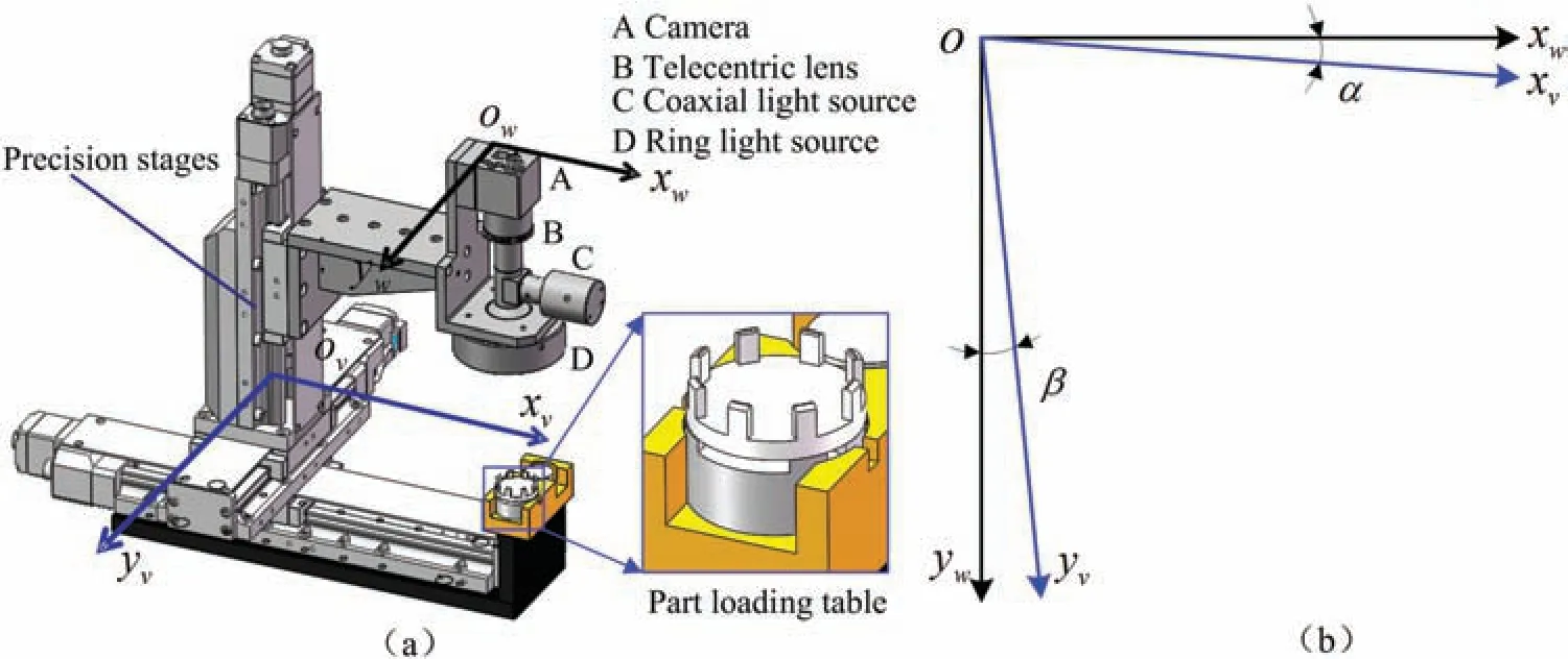
FIG.2.Microscopic visual device and installation angles:(a)coordinate system of visual device;(b)angles between visual system and world coordinate system.
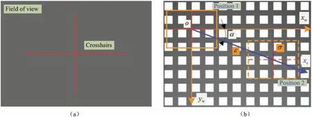
FIG.3.Calibration principle for α:(a)crosshairs of fiel of view;(b)calibration principle.
Taking account of the fact that the camera can capture only one arc structure at a time and considering the structure of the part and the hysteresis errors of the precision stages,the image acquisition path is shown in Fig.4.Hysteresis error is eliminated by returning to the initial position several times.The initial position of the measurement is located near the center of the part and is denoted byA0.The image acquisition path isA0,A1–A2,A0,A3–A4,A0,A5–A6–A7–A8,where the positions of the images are denoted byA1,A2,...,A8in order.When the visual system collects the image,we denote bydy1,dy2,dy5,dy6,anddy8the displacements due to motion in theYdirection and bydx3,dx4,dx5,anddx7those due to motion in theXdirection.
As shown in Fig.5,the image mosaic coordinates are established according to the image acquisition path,whereuovdenotes the coordinate system of the mosaic image,u0o0v0the initial position of the camera,andu1o1v1,...,u8o8v8the coordinates of images collected by the camera for the eight-section arc structures.
We denote by(x0,y0)the origin of the coordinate of the initial position of the visual device,which is a constant independent of the size of the part,and by(x1,y1),...,(x8,y8)the origins of the coordinates of the eight images collected by the visual system along the image acquisition path.Using Eq.(1)and the image acquisition path,the origins of the coordinates of the image mosaic are calculated for the eight images collected by the camera,as shown in Table I.A complete image can be obtained by using the origins of the image mosaic coordinates.
The image mosaic model with non-overlapping regions can be summarized as follows.Taking advantage of the high repeatability of the precision stages,the vision module utilizes them to move definit distances to capture local images of the part.In practice,however,owing to installation error,the precision stages are not in their ideal positions.This implies that there are angles between them.We therefore used an angle calibration plate to obtain the installation angles of the precision stages.Subsequently,based on the displacement due to motion and the geometric angles of the installation,an image mosaic model without overlapping regions was established to reduce the workload involved in image acquisition and mosaic construction.Thus,an image containing all information about the part can be acquired using the image mosaic model.
B.Experimental equipment
Figure 6 shows the experimental equipment.The microscopic vision system can be combined with the manipulator arm and other part loading tables to form a precision system for automatic assembly of parts.The manipulator arm can be used for operations on parts,such as their picking,transportation and assembly.In this case,the visual system can be used not only to inspect and select parts,but also to achieve alignment during the assembly process.The experimental equipment incorporated an industrial personal computer(IPC)with associated software to implement image acquisition,control of the brightness of the light source,and control of the motion of the precision stages to obtain the experimental images.

FIG.4.Image acquisition paths:(a)from A1 to A4;(b)from A5 to A8.
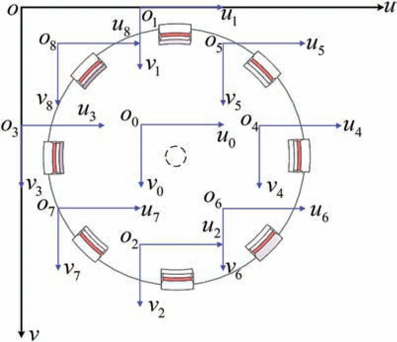
FIG.5.Image mosaic coordinates for the part.
On the basis of the principle of angle calibration illustrated in Fig.3,the installation angles of the precision stages were obtained asα=0.227○andβ=0.007○in Fig.2(b).
C.Specified calibration plate
The high repeatability of the stages is beneficia for the accuracy of the image mosaic.However,the systematic error caused by the movement of the precision stages cannot be ignored.Because the motion platform has high repeatability(0.5 μm),in applications,the precision stages perform the same motion tasks for the same kinds of parts.Therefore,the error generated by the precision stages is relatively stable and small for each measurement.This error can bemitigated by averaging multiple measurements,leading to a more precise value.
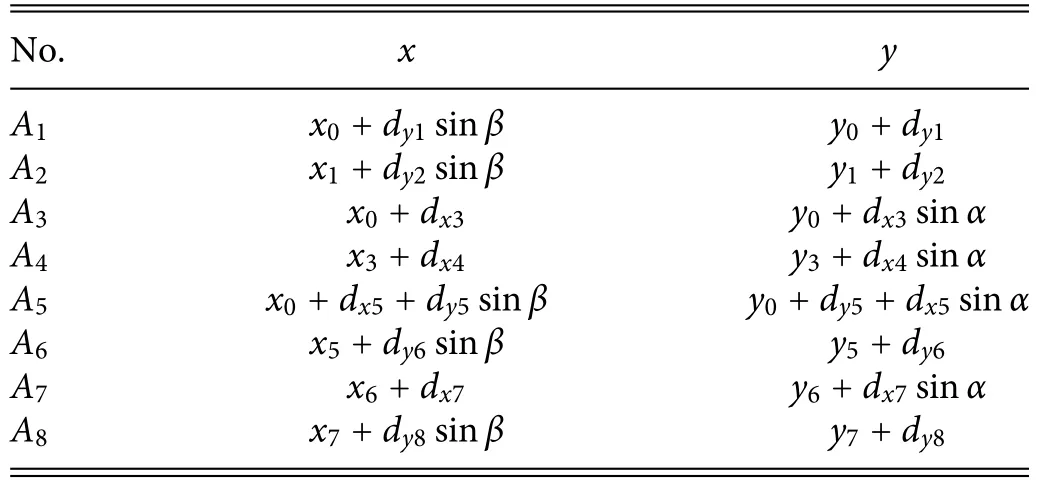
TABLE I.Origins of coordinates for image mosaic.
To determine the mosaic errors of this system,we designed a specifie calibration plate whose structure and inner diameter dimensions approximated the image of the part.As shown in Fig.7(a),its inner diameter was 21 980 μm and its dimensional accuracy was 1 μm.The visual system followed the same motion path to measure both the calibration plate and the actual part.The mosaic of the specifie calibration plate was calculated using the data presented in Table I.Thus,the inner diameters of the calibration plate were computed,and by comparing them with the standard values,it was possible to determine the error of the image mosaic.
The experimental results were described by assigning numbers to the arc structures of the calibration plate in a clockwise manner,mirroring the approach used for the actual part,and dividing them into four pairs with opposite positions.The respective inner diameters are denoted by,,,andin(I),(II),(III),and(IV)of Fig.7(b).
III.EXPERIMENTS AND DISCUSSION
For the specifie calibration plate,partial images were captured by the experimental device using the image acquisition paths described in Fig.4,as shown in Fig.8(a).By applying the proposed image mosaic method,the entire image could be acquired,as shown in Fig.8(b).
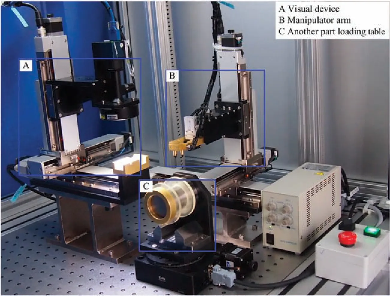
FIG.6.Experimental equipment.
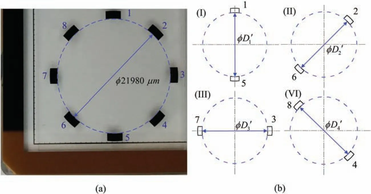
FIG.7.(a)Specifie calibration plate.(b)Diameters to be measured.
By using the visual system to measure the calibration plate 10 times and processing the entire image,the inner diameters were calculated using the least-squares method.The results are presented in Table II.
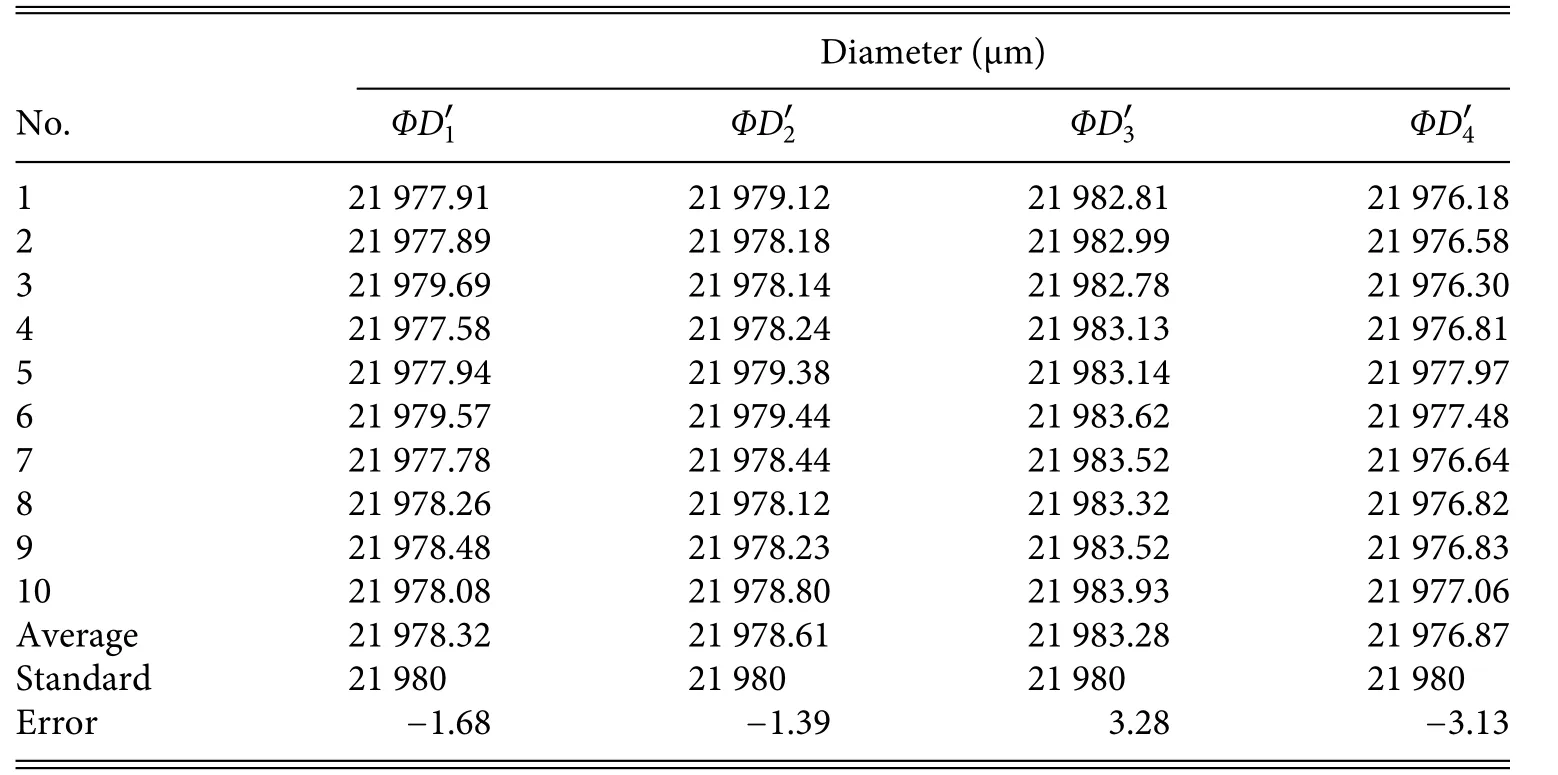
TABLE II.Results for the calibration plate.
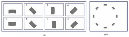
FIG.8.Images of calibration plate:(a)partial images;(b)image mosaic result for the calibration plate.
IV.RESULTS
The experimental apparatus similarly collected partial images for a part,as shown in Fig.9(a).The entire image can be produced using the image mosaic method,as shown in Fig.9(b).The values ofΦD1,ΦD2,ΦD3,andΦD4were calculated by processing the image mosaic results.
FIG.9.Images of the part:(a)partial images;(b)image mosaic result for the part.
TABLE III.Results for the part with compensation applied.
The actual measurement of the part was done ten times.Using the errors in Table II,we applied compensation to the results for the part to improve measurement accuracy.The results are presented in Table III.
The corrected average values are the measurement results for the part.If the results are within the tolerance range of the design size,then the part can be assembled.Otherwise,we must replace the part and conduct another measurement.
V.CONCLUSIONS
An image mosaic method with non-overlapping regions has been proposed.This method relies on the use of microscopic vision in precision assembly and compensation using a specifie calibration plate.The repeatability of each precision stage was 0.5 μm for a camera with pixel equivalent 2.46 μm,and the dimensional accuracy of the specifie calibration plate was 1 μm.Experimental results demonstrated a maximum deviation of less than 4 μm,which meets the assembly requirements of the parts being measured.The time needed for a single actual measurement was less than 120 s,which is adequate for practical applications.In summary,the proposed image mosaic method not only guarantees accuracy,but also reduces the workload involved in collecting partial images and the computational expense of image mosaic construction.
Thus,the image mosaic method with non-overlapping regions described in this paper provides a simple and precise technique for measurements in precision assembly.
ACKNOWLEDGMENTS
This work was supported by the Liaoning Revitalization Talents Program (Grant No.XLYC2002020) and the Major Project of Basic Scientifi Research of Chinese Ministry (Grant No.JCYK2016205A003).
AUTHOR DECLARATIONS
Conflict of Interest
The authors have no conflict to disclose.
DATA AVAILABILITY
The data that support the finding of this study are available from the corresponding author upon reasonable request.
杂志排行

纳米技术与精密工程的其它文章
- Stress distribution variations during nanoindentation failure of hard coatings on silicon substrates
- Electrode design for multimode suppression of aluminum nitride tuning fork resonators
- Effects of simulated zero gravity on adhesion,cell structure,proliferation,and growth behavior,in glioblastoma multiforme
- Design and analysis of longitudinal–flexuralhybrid transducer for ultrasonic peen forming
- An advanced cost-efficient IoT method for stroke rehabilitation using smart gloves
- Electrical characterization of an individual nanowire using flexible nanoprobes fabricated by atomic force microscopy-based manipulation