Design and analysis of longitudinal–flexuralhybrid transducer for ultrasonic peen forming
2024-01-08WuqinLiYongyongZhuXiaolongLuHuafengLiYingWeiPengweiShangandBoFeng
Wuqin Li, Yongyong Zhu, Xiaolong Lu,,a) Huafeng Li, Ying Wei, Pengwei Shang, and Bo Feng
AFFILIATIONS
1 State Key Laboratory of Mechanics and Control for Aerospace Structures,Nanjing University of Aeronautics and Astronautics,Nanjing 210016,China
2Institute of Dynamics and Vibration Research,Leibniz Universität Hannover,An der Universität 1,Garbsen 30823,Germany
ABSTRACT Ultrasonic peen forming(UPF)is an emerging technology that exhibits great superiority in both its flexibl operating modes and the deep residual stress that it produces compared with conventional plastic forming methods.Although ultrasonic transducers with longitudinal vibration have been widely studied,they have seldom been incorporated into UPF devices for machining in confine spaces.To meet the requirements of this type of machining,a sandwich-type piezoelectric transducer with coupled longitudinal–flexura vibrational modes is proposed.The basic structure of the transducer is designed to obtain large vibrational amplitudes in both modes.Experimental results obtained with a prototype device demonstrate the feasibility of the proposed transducer.The measured vibrational amplitude for the working face in the longitudinal vibrational mode is 1.0 μm,and electrical matching increases this amplitude by 40%.The flexura vibration characteristics of the same prototype transducer are also tested and are found to be slightly smaller than those of longitudinal mode.The resultant working strokes of the UPF impact pins reach 1.7 mm and 1.2 mm in the longitudinal and flexura modes,respectively.The forming capability of the prototype has been evaluated via 15-min machining on standard 2024-T351 aluminum plates.After UPF,an improved surface morphology with lower surface roughness is obtained.The aluminum plate test piece has an apparent upper deformation with an arc height of 0.64 mm.The measured peak value of the compressive residual stress is around 250 MPa,appearing at a depth of 100 μm.The proposed longitudinal–flexura hybrid transducer thus provides a high-performance tool for plate peen forming in confine spaces.
KEYWORDS Ultrasonic peen forming,Piezoelectric transducer,Longitudinal–flexural vibrational mode,Modal analysis
I.INTRODUCTION
Peen forming,a technique that is extensively used in metalworking,uses the impact of high-speed rigid particles1on the surface of a metal plate workpiece to cause plastic deformation of the latter.2The machining-induced reconstruction of the residual compressive stress3,4helps to improve the fatigue resistance and strength of the workpiece.5–8As a new cold working process for metals,ultrasonic peen forming (UPF) shows better controllability,deeper residual compressive stress,and better surface roughness of the machined parts than traditional methods.9–11In addition,the working media(particles or impact pins)of UPF can be recycled after peening,which effectively reduces pollution and makes UPF a highly promising technique from the perspective of green manufacturing.12–15
With the aim of realizing efficien deformation,a number of critical factors that can influenc UPF have been systematically investigated.16Lu and co-workers17,18and Huet al.19described the influenc of current,impact pin diameter,peening trajectory,impact times,impact velocity,and other factors on metal plate deformation from the perspective of compressive stress.Huet al.20investigated the ways in which peening time and intensity together affected arc height.Gariepyet al.21,22investigated the influenc of rolling orientation and peening trajectory on forming behavior.
TABLE I.Materials and mechanical properties of different parts of the transducer.
FIG.1.Structure of the UPF device:(a)transducer configuration (b)different operating attitudes for UPF.
Liuet al.23and Luet al.24found experimentally that UPF performance could be enhanced under extraordinary vacuum conditions.Guoet al.25used numerical simulation to investigate the relationship between shot peening and plate deformation.Such simulations can be used for optimizing the parameters for UPF machining.
Most UPF processing uses ultrasonic transducers working in longitudinal mode,and thus the transducers need to be placed vertically with respect to the workpiece,which makes it diffi cult to carry out peening operations in a confine space.This problem can be overcome through the use of hybrid transducers with coupled longitudinal–flexura modes.Such hybrid transducers have been developed and used in a variety of other applications.Liu and co-workers26–29have proposed several geometrical designs for sandwich-type piezoelectric transducers operating in longitudinal–flexura hybrid vibrational modes.For applications in spin-machining,Liet al.30proposed a longitudinal–flexura coupled horn for a giant magnetostrictive transducer that reduced the influ ence of structural parameters on performance.These methods have enabled improvements to be made to output functions and operating flexibilit without the need for significan changes to transducer structure.

TABLE II.Axial lengths of different parts of the transducer.

FIG.2.Simulation of the transducer:(a)longitudinal vibrational mode(L-mode);(b)flexura vibrational mode(F-mode).
With the aim of developing hybrid ultrasonic transducers for UPF,the basic working performance when using dual vibrational modes to trigger the movement of impact pins needs to be explored.In this study,we propose a hybrid ultrasonic transducer to address the issue of operating attitude in the processing of thin plates with complex configurations To combine both longitudinal and flexura vibrations,two different groups of piezoelectric wafers are employed in a single ultrasonic transducer to independently excite the corresponding resonance modes.The configuratio and dimensions of the hybrid ultrasonic transducer are designed on the basis of numerical simulations.The results of these simulations indicate that effective vibration of the working face can be achieved and that his can be increased through the use of series inductance matching.The UPF performance using the hybrid transducer is verifie by application to 2024-T351 plates of thickness 10 mm.The feasibility of the proposed hybrid transducer is evaluated from the aspects of surface morphology,arc height,and surface residual compressive stress.
II.STRUCTURE DESIGN AND WORKING PRINCIPLES
A.Geometrical design of the transducer
FIG.3.Assembled hybrid transducer.
The proposed longitudinal–flexura hybrid transducer for UPF consists mainly of a piezoelectric vibrator and a stepped sonotrode,as shown in Fig.1(a).Two groups of piezoelectric ceramics are clamped between the front and the back mass blocks,with opposite polarization directions for neighboring coaxial piezoelectric ceramics.This is because it is easier to achieve longitudinal vibration with a unipolar piezoelectric ceramic and flexura vibration with a bipolar piezoelectric ceramic.The firs group of two unipolar piezoelectric ceramics is placed adjacent to the back mass block,driving the transducer to vibrate longitudinally when excited by high-frequency AC signals at resonant frequency.Another group of four bipolar ceramics is placed next to the front mass block,driving the flexura vibrational mode of the transducer.Both longitudinal and flexura vibrational modes(theL-mode andF-mode,respectively)can be utilized to drive the accelerations of impact pins and enable the UPF processing with different operating attitudes,as shown in Fig.1(b).Compared with the conventional UPF method,which needs at least a 220 mm space for working,the proposed UPF device under theF-mode needs only 89 mm in the vertical direction,thus significantl reducing the required height of the operating space.
B.Modal analysis of transducer
To evaluate the effective excitation for the natural resonance of the longitudinal–flexura UPF transducer,COMSOL Multiphysics software was used to simulate the vibrational modes of the transducer.A frequency-domain analysis was performed to evaluate the detailed vibrational amplitude under a given natural frequency and driving voltage.For optimization,the dimensions of the transducer were continuously adjusted to achieve large vibrational amplitudes at the working face in both longitudinal and flexura modes.
FIG.4.Measurements of longitudinal and flexura vibrations:(a)vibrational response in L-mode;(b)vibrational response in F-mode.
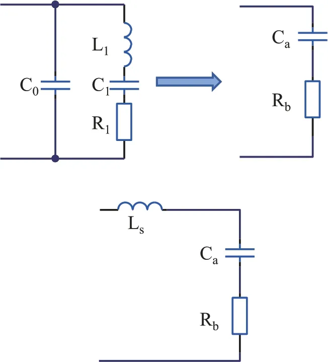
FIG.5.Equivalent circuit of the transducer and the series matching method.
In this simulation,the piezoelectric ceramics were PZT-8,with densityρ=7600 kg/m3and piezoelectric constantd33=243 pC/N.With regard to the fixe dimensions(∅15×∅40×5 mm3)of piezoelectric ceramics,the same 40 mm external diameter was chosen for the front and back mass blocks.Other materials used for simulation are shown in Table I.For simulation of the longitudinal vibrational mode shown in Fig.2(a),the adjacent surfaces of the firs group of unipolar ceramics were set as U+(∼50 V),with the two sides set as U-(∼0 V).Meanwhile,the frequency domain was set to the range 10–30 kHz.After several simulations with the length of the sonotrode being varied,the optimized results showed that the transducer exhibited a second-orderL-mode with modal frequency 22.524 kHz and with three different sections of the stepped sonotrode,namely,a circle of diameter 26 mm,a square of side length 40 mm,and a square of side length 30 mm.The axial lengths of each segment of the transducer are shown in Table II.With these geometrical parameters,the second-order longitudinal vibrational amplitude was about 1 μm.Using the same driving conditions applied to the second group of bipolar piezoelectric ceramics,the obtained modal frequency for the third-orderF-mode was around 12.6 kHz and the calculated vibrational amplitude on the working face was about 1 μm [Fig.2(b)].Although the frequency of the third-orderF-mode was lower than the ultrasonic frequency,its vibrational effect was the best compared with the transducer’sF-mode frequency points above the ultrasonic frequency at other orders.Such a phenomenon is also demonstrated in the following sections and in Fig.4(b).
C.Vibrational characteristics of the transducer
Adopting the structural dimensions determined above,a prototype hybrid transducer was fabricated.We found that the transducer admittance circle measured by an impedance analyzer was most regular after the application of a preload of 2 tons.To better transmit vibrations and avoid fracture of the piezoelectric ceramics,the applied preload adjusted by the screw bolt was 2 tons.A photograph of the assembled prototype transducer is shown in Fig.3.
The vibration of the two working faces of the transducer was measured by a laser Doppler vibrometer.It can be observed from theL-mode response in Fig.4(a),obtained under an excitation voltage of 100 Vp-p(peak-to-peak) and a swept frequency range of 10–30 kHz,that there are multiple vibrational velocity peaks and that the highest,fs1,is locates at the driving frequency of 20.367 kHz,which is close to the simulated longitudinal resonance frequency.TheF-mode response shown in Fig.4(b) also exhibits multi-order flexura vibrational modes,with the highest peakfs2occurring at 11.519 kHz.Under the 100 Vp-pdriving voltage,the measured vibrational amplitudes of theL-andF-modes were 1.0 μm and 0.8 μm,respectively.
III.RESULTS AND DISCUSSION
A.Effect of electrical matching
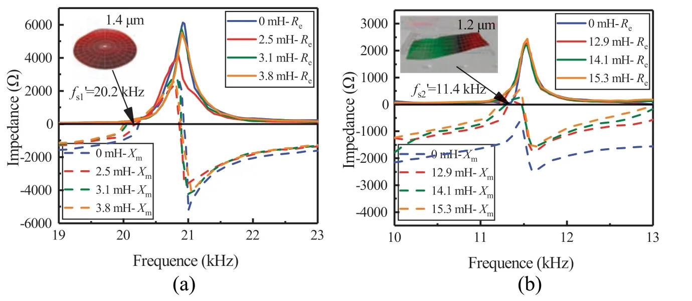
FIG.6.Electrical analysis after series matching:(a)L-mode;(b)F-mode.
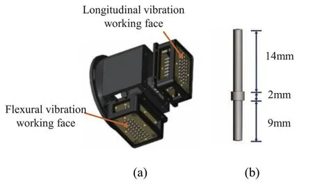
FIG.7.Impact head for the UPF processing:(a)configuratio of impact head;(b)dimensions of impact pin.
The equivalent circuit of a piezoelectric transducer is determined by its vibrational modes.In general,for a transducer with a single vibrational mode,the equivalent circuit near the resonant frequency is a complex combination of a shunt capacitanceC0,a dynamic inductanceL1,a dynamic capacitanceC1,and a dynamic resistanceR1,31as shown in Fig.5.For a piezoelectric transducer at resonance,the effects of the dynamic inductanceL1and dynamic capacitanceC1on its branches are reduced,and the equivalent circuit is then a parallel connection of resistive–capacitive elements and appears capacitive externally.32In addition,since the equivalent elements of the transducer vary near the resonant frequency,it is difficul to accurately obtain the impedance of the transducer.Therefore,it will be taken to be equivalent to a series connection of a capacitive elementCaand a resistive elementRb,with a series inductanceLsbeing used to compensate the load circuit to ensure that it is in a purely resistive state.
Using measured peak voltageUmaxand peak currentImaxof the transducer and the time difference ΔTbetween them under actual driving conditions,the impedanceZTof the transducer is computed as follows:
whereφis the phase difference between voltage and current(and is also the impedance angle of the transducer),fis the working frequency of the transducer,andReandXmare respectively the real and imaginary parts of the impedance.
Inductance matching can significantl improve the electromechanical coupling coefficien and reduces the resonant frequency of the load circuit.The selected working frequenciesf′s1andf′s2of the longitudinal and flexura vibrational modes are lower than the series resonance frequencies.The transducer is capacitive,and the matched series inductance is given by
The calculated matched inductances of the longitudinal and flexura vibrational modes are 3.1 mH and 14.1 mH,respectively.Figure 6 shows the impedance of the load circuit after matching based on the theoretically calculated matched inductance.The tiny discrepancy between the theoretical inductance for matching and the parameter applied in experiments to achieve a purely resistive state can be attributed to the measurement error related to the precision of the equipment.After series connection of an inductor with inductance slightly less than the theoretical value (2.5 mH for theL-mode and 12.9 mH for theF-mode),the transducer becomes purely resistive at the new working frequency,and the maximum vibrational amplitudes of the working faces for theL-andF-modes increase to 1.4 μm and 1.2 μm,respectively.
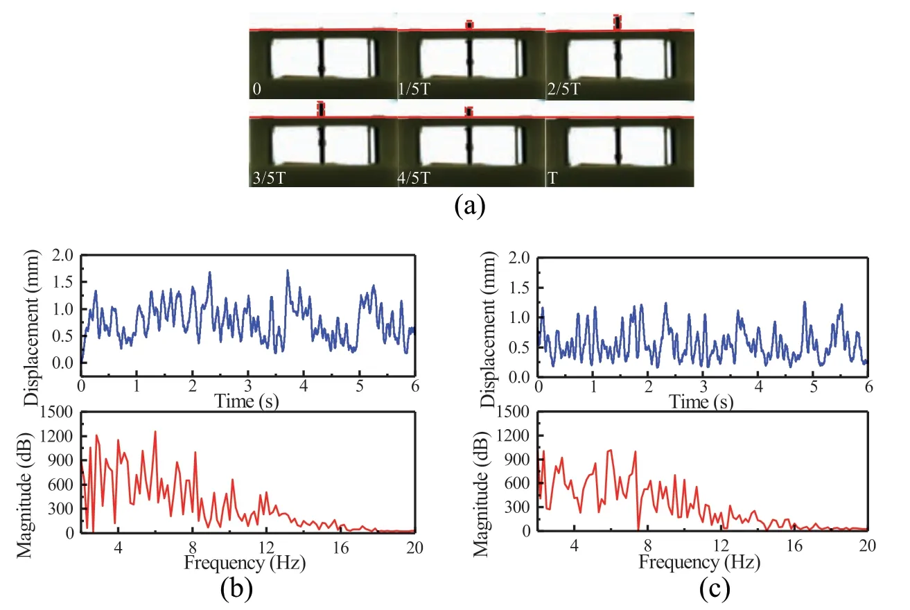
FIG.8.Low-frequency movement of impact pin:(a)impact pin trajectory in a single period;(b)impact displacement vs time and frequency in L-mode;(c)impact displacement vs time and frequency in F-mode.
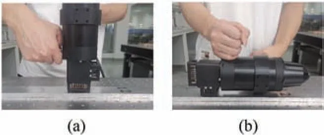
FIG.9. On-site UPF processing with different attitudes in (a) L-mode and (b) Fmode.
B.Movement behavior of impact pins
When the driving circuit integrated with series matching is used,the hybrid transducer can be powered using output AC signals with voltage of 100 V at resonance frequencies ofand.To perform UPF,one impact head containing four rows of impact pins with an interval of 4 mm was designed to interact with theL-andFmode working faces,as shown in Fig.7(a).The details of the impact pin are shown in Fig.7(b).It consists of three stepped sections with respective diameters of 2 mm,3 mm,and 2 mm and lengths of 9 mm,2 mm,and 14 mm.
To examine the rapid impact movement,a high-speed camera recorded the displacement of a single impact pin within a certain period,as shown in Fig.8(a).Another laser displacement sensor was employed to quantify the exact positions of the pin in both modes,with a sampling period of 0.2 ms.It can be observed from Figs.8(b) and 8(c) that the pin had an impact frequency that was much lower than the excitation signal and that the impact stroke fluctuate in different duty cycles.The impact pins are designed to be consumable parts of the device and are thereforenot fixe to the transducer,but instead are driven by its working face.Thus,the pins undergo multiple processes,including strike,impact,and rebound,as a consequence of which the frequency with which they impact on the workpiece will be lower than the vibration frequency of the transducer to which they are subjected.Within the recording time of 6 s,the maximum displacements of the impact pin were 1.7 mm and 1.3 mm in theLandF-modes,respectively.These measured impact strokes basically agrees with the results of the simulation and the vibration performance.
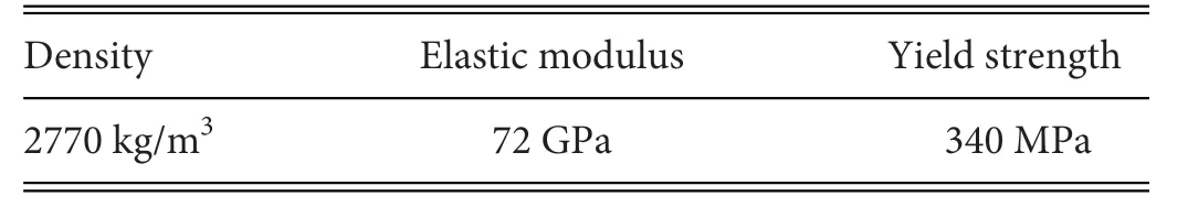
TABLE III.Mechanical properties of 2024-T351 aluminum alloy.
The prototype system for UPF and the two operating attitudes are illustrated in Fig.9.The impact head was assembled with the hybrid transducer through the enclosure to ensure that both working faces are able to strike the impact pins along their vertical direction.It can be observed that such system can accomplish UPF processing in theL-mode,and theF-mode in the other operating attitude can easily be enabled by simply changing from the vertical working face to the horizontal one.The test results described above have shown that the vibrational amplitude of theL-mode is larger than that of theF-mode.Therefore,whenever possible,i.e.,provided there is sufficien working space,theLmode should be selected as the main working mode of the transducer.When the working space is restricted,theF-mode is more appropriate.
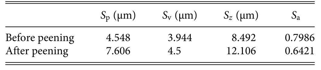
TABLE IV.Roughness parameters before and after peening.
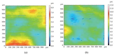
FIG.10.Surface morphology of plate(a)before and(b)after UPF.
C.Surface morphology measurement
Since the striking movements of the impact pins in both working modes have now been demonstrated,the following discussion focuses on improving the surface quality and morphology of the workpiece when using UPF.33–35Ultrasonic peening is widely used in the aerospace,automobile,and shipbuilding industries for surface treatment and forming of metals,including,for example,aluminum alloys,spring steel,and titanium alloys.A typical aluminum alloy used in aeronautic applications (No.2024-T351) was selected for testing here.Its mechanical properties are shown in Table III.The dimensions of the workpiece were 800 × 50 × 10 mm3.For the 15 min of ultrasonic peening,the impact pins were perpendicular to the workpiece and moved along the length direction.Unless specified these processing parameters were set as the default for the subsequent UPF machining.
In general,the surfaces of most metal plates exhibit a small amount of roughness produced by conventional manufacturing processes.Decreasing this roughness is very useful for enhancing fatigue strength and corrosion resistance.36Figure 10 shows the surface morphology of the workpiece before and after UPF using the proposed hybrid transducer.Table IV shows the pre-and post-peening values of the parameters specifie in the ISO25178 standard37for characterizing roughness.The maximum surface heightSzis equal to the sum of the maximum peak heightSpand the maximum valley depthSv,38but it is greatly affected by scratches,pollution,and measurement noise.The contour parameterZ(x,y) is extended to 3D,and the arithmetical mean surface heightSais then define as39
In general,the surface roughness of the test workpiece was greatly reduced by the UPF.The overlapping of pits induced by the continuous injection helped to compact the contours and reduce the roughness valueSa.The experimental results also show that the surface became smoother when the peening time was extended.
D.Formability evaluation
Finally,the formability as represented by the change in arc height of the machined workpiece following processing with the prototype UPF system and the aforementioned processing parameters was evaluated.As shown in Fig.11,the arc height of the workpiece reached 0.32 mm in the firs 5 min of processing in theL-mode.It then gradually increased by 0.22 mm in the next 5 min and reached a stable deformation of 0.64 mm after 15 min.A similar trend of arc height variation during peening was also observed inF-mode processing,which generated a slightly smaller arc height of 0.55 mm.It can be seen from the deformation results that the vibrational amplitude of the impact pins(as shown in Fig.8) has the dominant influenc on the formability of the workpiece.
To obtain a deeper understanding the mechanism underlying UPF,the residual stress fiel distribution on the workpiece surface was measured by an x-ray method.Combined with layer-by-layer electrolytic polishing,the residual stress at different depths can be analyzed at selected points where the arc height of the deformed
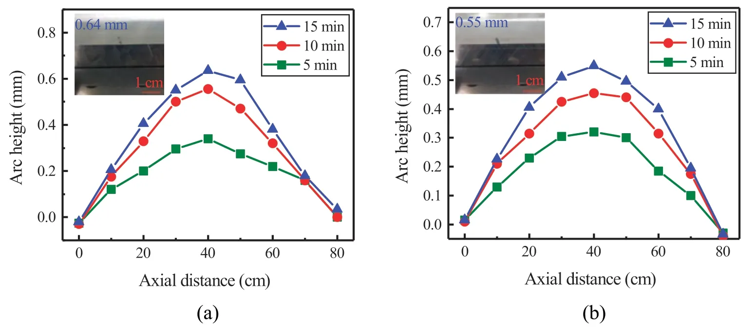
FIG.11.Arc height variation during UPF:curvature of arc height in(a)L-mode and(b)F-mode.
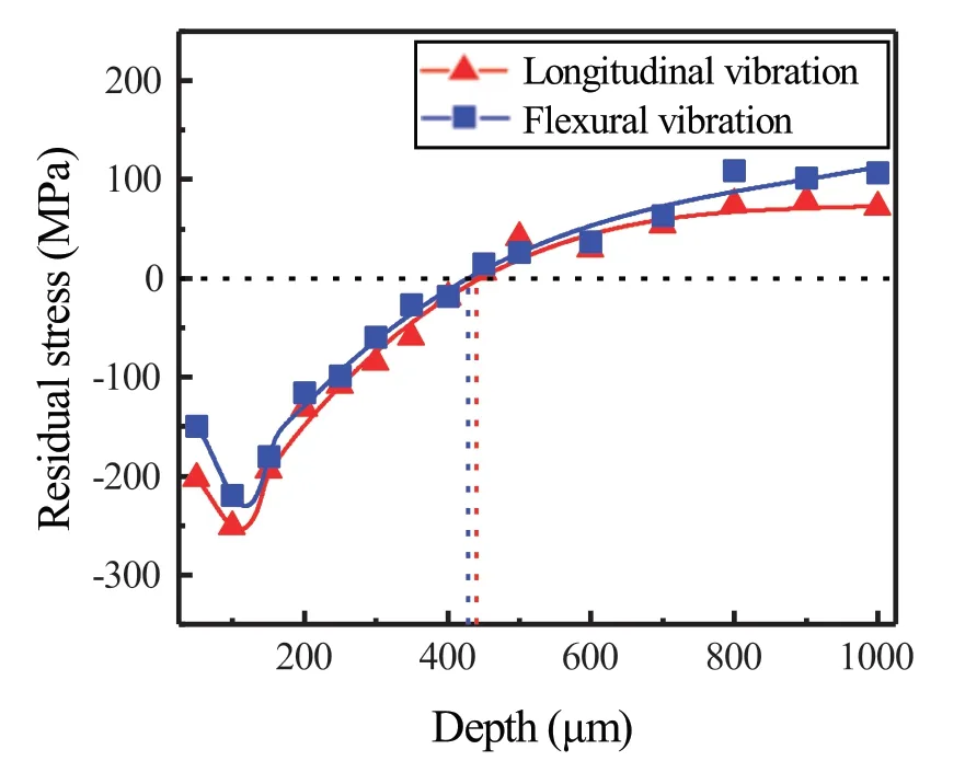
FIG.12.Residual stress distribution in the two UPF working modes.
2024-T351 workpiece changed significantly Figure 12 shows the measured residual compressive stress at a depth of about 100 μm.The maximum residual compressive stresses for theL-andF-modes were 251 MPa and 220 MPa,respectively.In addition,the residual compressive stress afterL-mode processing decreased to zero at a depth of 440 μm,which is greater than the corresponding depth of 430 μm inF-mode processing.The results indicate that the striking displacement of the impact pins determines the depth of residual compressive stress and the resulting geometrical deformation.It can also be seen that bothL-mode andF-mode operation are effective for UPF,demonstrating the good performance of the prototype hybrid transducer.
IV.CONCLUSIONS
In this study,a sandwich-type hybrid piezoelectric transducer with coupled longitudinal–flexura vibrational modes has been proposed.The influenc of electrical matching on vibrational amplitude has been analyzed,the movement behavior of the impact pins has been tested,and the formability obtained using the proposed UPF device has been evaluated.Experimental results confir that series matching can significantl improve the vibrational amplitude of the ultrasonic transducer.BothL-andF-modes can reconstruct the residual compressive stress layer of the workpiece,resulting in good forming capability of the workpiece.This study focusing on multi-mode operation has laid the groundwork for the development of UPF devices capable of machining in narrow and small spaces.
ACKNOWLEDGMENTS
This work was supported by the National Natural Science Foundation of China (Grant Nos.51975278 and 52277055),the Qing Lan Project,the Research Fund of the State Key Laboratory of Mechanics and Control of Mechanical Structures (Nanjing University of Aeronautics and Astronautics) under Grant No.MCMS-I-0321G01,the Biomedical Engineering Fusion Laboratory of the affiliate Jiangning Hospital of Nanjing Medical University (Grant No.JNYYZXKY202217),the Postgraduate Research &Practice Innovation Program of NUAA (Grant Nos.xcxjh20220114 and xcxjh20220111),and the Postgraduate Research&Practice Innovation Program of Jiangsu Province (Grant No.KYCX23_0353).
AUTHOR DECLARATIONS
Conflict of Interest
The authors have no conflict to disclose.
DATA AVAILABILITY
The data that support the finding of this study are available from the corresponding author upon reasonable request.
杂志排行

纳米技术与精密工程的其它文章
- Stress distribution variations during nanoindentation failure of hard coatings on silicon substrates
- Electrode design for multimode suppression of aluminum nitride tuning fork resonators
- Effects of simulated zero gravity on adhesion,cell structure,proliferation,and growth behavior,in glioblastoma multiforme
- An advanced cost-efficient IoT method for stroke rehabilitation using smart gloves
- Electrical characterization of an individual nanowire using flexible nanoprobes fabricated by atomic force microscopy-based manipulation
- An image mosaic technique with non-overlapping regions based on microscopic vision in precision assembly