Ultra-Wideband Millimeter-Wave Vortex Beam Generation Based on Refective Pancharatnam-Berry Phase Metasurface
2024-01-06TingtingZhangXuehongSunYanpengZhangLipingLiu
Tingting Zhang,Xuehong Sun,Yanpeng Zhang,Liping Liu
Abstract—Due to the gradual scarcity of spectrum resources,orbital angular momentum (OAM) technology has been proposed and developed continuously to broaden channel capacity.To solve this problem,some ultra-wideband reflective phase metasurface antennas working in millimeter band are designed to generate high purity vortex waves which carry OAM.Based on the Pancharatnam-Berry (PB) phase concept,the unit cell is composed of a metasurface,dielectric,metal grounding layer.Through the optimization design of the unit structure parameters,the reflected wave efficiency can be as high as 95% when covering 2π rotating phase,which realizes the basic requirements of PB phase concept and the relative bandwidth of 116%.Then the metasurface arrays are arranged according to vortex wave generation formula and phase compensation principle.In the 25 GHz to 35 GHz frequency wide band,integer (l=±1,±2,±3)decimal (l=±1.5) and high-mode (l=±8) OAM vortex beams are generated,respectively.The OAM purity analysis shows that the antennas can generate millimeter wave OAM beams with high purity in a wide band range,and with a maximum gain of up to 23.6 dBi.
Keywords—Orbital angular momentum (OAM);millimeter wave;ultra-wideband;metasurface;Pancharatnam-Berry(PB)phase
I.INTRODUCTION
Orbital angular momentum(OAM)has a variety of modes,and the vortex electromagnetic waves with different modes are orthogonal to each other.Through the dependency of modes,multiple coaxial data streams can be sent without relying on traditional resources such as time and frequency,providing a new reuse dimension of wireless transmission,thereby improving spectral efficiency.The existence of OAM has long been theoretically proven,but significant progress has only been made in this century.In 1909,Franklin[1]recognized that circularly polarized light has spin angular momentum (SAM).In 1992,Allen et al.[2]proposed that the OAM of a beam is independent of the SAM,thus establishing the relationship between helical phase beams and OAM.Nowadays,the methods of generating OAM usually include spiral phase plate[3-4],parabolic antenna[5-6],uniform ring antenna array[7-8],dielectric resonator[9-10],holographic phase plate[11-12].But these design methods have some problems,such as large volume,insufficient purity,and complex feed network.
Metasurface antenna uses plane wave transmission or refection in the propagation process to make the beam obtain a specific phase difference at different azimuths,so as to generate vortex beam[13].One kind of metasurface can realize phase change by changing the geometric parameters of different resonant elements[14-16].However,controlling abrupt phase based on geometric parameter change is difficult to achieve high broadband and high performance,and can only generate linearly polarized OAM vortex waves.Using the Pancharatnam-Berry (PB) phase principle,abrupt changes in phase,polarization and amplitude of electromagnetic waves can be easily generated on a small and ultra-thin plane.Based on the phase metasurface,Ran et al.[17]proposed a doublearrowhead metasurface designed in ku-band,which achieved a transmission efficiency of 75.76%.Liu et al.[18]proposed a three-layer square ring frequency selective surface,operating at 12 GHz and 18 GHz respectively,four kinds of refecting vortex beams are generated under normal incidence,which can also be used as focusing lenses while generating OAM.Using the PB phase principle,Xu et al.[19]designed two 8×8 planar arrays in X-band to generate four vortex beams with different directions,and then decouple them.Finally,the relative bandwidth is 33.4%.In the microwave frequency band,Zhang et al.[20]mentioned the OAM generated by the ultra-thin superlens is used to converge the vortex beam without diffraction,which proves that the low-order OAM vortex beam generated by the superlens and can exhibit a focused beam.Han et al.[21]mentioned a 4-layer structure which was adopted to achieve 40%of the relative bandwidth and generate higher performance OAM vortex waves.Al-Nuaimi et al.[22]proposed a single layer structure which was used to design a metasurface with an efficiency of more than 83% for three modes.However,these array antennas produce almost only low-order integer modes,and are not concerned with higherorder and fractional modes.
In this paper,a refective metasurface array with inner and outer double ring structure is proposed to generate integer,fractional,and high-order vortex beams in the millimeter wave band.When designing a metasurface unit,the conversion efficiency is close to 100% after parameter optimization.The metasurface has been calculated to produce OAM patterns of particularly high purity and gains of up to 23.6 dBi.
II.DESIGN THEORY AND METHOD
It is known that a photon can have two kinds of angular momentum,namely linear momentum and angular momentum.The angular momentum can be divided into two types,namely SAM and OAM[22].The theoretical basis for converting SAM into OAM is the Jones matrix[23],which is convenient and clear in analyzing the incident field and scattered field of the metasurface.The refected field and incident field can be connected by the refection coefficient of the Jones matrix,as shown in(1)below.
whererxx,ryy,rll,andrrrare the co-polarization refection coefficients under the normal incidence ofx,y,left circular polarization and right circular polarization respectively,andrxy,ryx,rlrandrrlare the corresponding cross polarization refection coefficients.In (1a) and (1d),e2jkφis a phase mutation atom,so the unit produces a rotation angle ofkφ,and the phase wavefront of the spiral can be obtained by the metasurface composed of elements with different rotation angles.If the unit element studied is symmetric,the element characteristics of the refection matrix of the rotated element can be obtained by using its symmetry.By introducing the rotation matrix as shown in(3),the refection matrix can be obtained as shown in(2)below.After a certain rotation angle,the rotation matrix can completely return to the initial state due to the symmetry of the element.
When incident with circular polarization,the refection matrix can be written as
In order to meet this requirement,it is necessary to have a high refection coefficient when designing metasurface elements,which satisfies[24]
III.UNIT STRUCTURE ANALYSIS
The metasurface element has three layers,which are metasurface,dielectric layer,and ground layer respectively.As shown in Fig.1,the top layer is composed of two parts: the outer ring and the inner patch,and the middle is the dielectric layer,whose material is F4B,and the dielectric constant is 2.65 when the loss tangent angle is 0.001[25].It has excellent high-frequency characteristics and can transmit signals stably and high-speed in high-frequency environment.The metasurface element adopts a symmetrical structure,so that it can produce different phases through rotation,and has achieved the purpose of phase coverage and satisfies the PB phase condition.
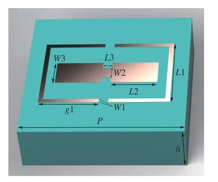
Fig.1 Cell parameters and 3D diagram
Different parameters of the patch unit are simulated and their effects on the refection amplitude and phase are analyzed in order to obtain the optimal values of the unit parameters.As can be seen from the cell structure diagram,the length of parameterL1 is strictly required,which is the outer ring should not overlap with the inner patch,and the cycle range of the patch unit should not be exceeded when the patch is rotated.Therefore,its parameters are optimized,as shown in Fig.2(a).It can be seen that whenL1=1.8,its phase coverage is the widest and its amplitude is also high.The size of the inner ring patch also has a significant infuence on the phase and amplitude of the element.Therefore,the optimization simulation ofL2 andW3 parameters is carried out at the same time.The simulation results are shown in Fig.2(b).It can be seen that the amplitude and phase are better whenL2=1 andW3=0.6.Through parameter optimization simulation,the optimal parameters of the metasurface element are obtained under the condition of periodic simulation,where the unit periodPis 4 mm,other geometric parametersL1=1.8 mm,L2=1 mm,L3=0.2 mm,W1=0.1 mm,W2=0.3 mm,W3=0.6 mm,g1=1.3 mm,andh=1 mm.
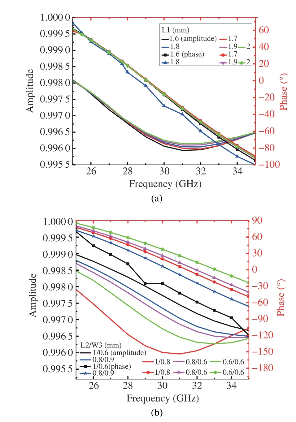
Fig.2 Unit cell optimization simulation results: (a)L1;(b)L2/W3
IV.CELL STRUCTURE SIMULATION RESULTS AND ANALYSIS
Electromagnetic simulation software CST STUDIO SUITE was used to conduct periodic boundary condition simulation analysis of the unit[26],and the simulation results of ultrawideband high performance were obtained,as shown in Fig.3.Fig.3(a) shows the co-polarization parameters and phase of the unit in the frequency range of 25-35 GHz under online polarization incidence.

Fig.3 Unit cell simulation results: (a) refected phase and amplitude linearly polarized(LP)incident;(b)circularly polarized(CP)
The co-polarization refection coefficients of the metasurface elements in bothxandydirections are infinitely close to 1,and the phase coverage also satisfies the conditions.Fig.3(b)shows the co-polarization,cross-polarization and refection efficiency of the unit under circular polarization incidence.It can be seen from the figure that,under circular polarization incidence,the co-polarization refection coefficient of the ultra-wide band (UWB) atom in the bandwidth range is greater than 0.9,and its refection efficiency is greater than 0.95 in most ranges of the frequency band.
It is known that the metasurface antenna is obtained by the unit rotation arrangement according to(6).Therefore,the copolarization refection efficiency of the unit with different rotation angles is further simulated to verify,which is a great improvement compared with the previous 8-order and 16-order quantization manual arrangement[27].Since the metasurface element is symmetrical,it is necessary to mention whether the metasurface element meets the design requirements in the rotation angle of 0-π.In the simulation,periodic boundary conditions are adopted for the element and circularly polarized wave is adopted.Fig.4 shows the co-polarization refection coefficients and phases of subunits with different rotation angles in the wide band range.It can be seen from the figure that the conversion efficiency of metasurface elements with different rotation angles is greater than 0.9 and their phase coverage is greater than 2π in the broadband range.At the same time,in order to further improve the performance of the unit,the return loss coefficient of each rotation angle unit is simulated.As shown in Fig.4(c),its S11 parameter is less than-10 dBi in the whole frequency range,indicating that the unit has good performance.

Fig.4 Phase and co-polarized refection coefficient of the cell at different rotation angles: (a)co-polarized refection coefficient;(b)phase;(c)S11 parameters
V.METASURFACE DESIGN AND SIMULATION
Based on the unit of metasurface,when designing the metasurface,due to the energy loss of each metasurface element under the incident feed,the phase compensation formula[28]should be met,as shown below.
where(x,y)is the central coordinate of each unit,andlis the mode number of OAM.
By adjusting the rotation angle of the unit,the phase compensation of each unit is satisfied.It should be noted that when rotating the element,the rotation angle is twice the phase of the element[29].As shown in Fig.5,there are five 20×20 metasurface arrays,respectively integral modesl=±1,±2,±3,fractional modesl=±1.5,and higher-order modesl=±8,which are programmed by MATLAB and modeled automatically in conjunction with the electromagnetic simulation software high frequency structure simulator(HFSS).

Fig.5 Layout of metasurface arrays with different modes: (a) l=±1;(b)l=±1.5;(c)l=±2;(d)l=±3;(e)l=±8
The Archimedean helix is placed 50 mm away from the metasurface to act as a feed antenna which incidents circularly polarized plane wave.By using CST STUDIO SUITE,the vortex beams with OAM modes of-1,-1.5,-2,and-3 are generated respectively.As shown in Fig.6,the far-field images of different modes at 28 GHz,30 GHz,and 32 GHz show that the gain is zero at the phase center and is in a vortex shape.As can be seen from Fig.6,the metasurface with different modes produces doughnut-shaped amplitudes and vortex phases on the reference plane,which conforms to the characteristics of OAM waves,indicating that the metasurface meets the design requirements.
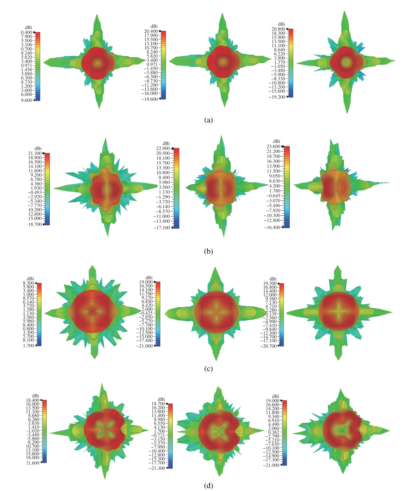
Fig.6 From left to right,the 3D far-field plots at different frequencies with 28 GHz,30 GHz,and 32 GHz: (a)l=-1;(b)l=-1.5;(c)l=-2;(d)l=-3
In order to further analyze OAM mode purity,Fourier transform formula can be used to analyze the mode purity under each OAM mode.By expanding the vortex wave modes and observing the spectral coefficientsAlof each mode,the calculated spectral coefficients show more and more that the power proportion of the mode is greater,the equation is shown in(7)[30].
where theψ(φ) is a function along thezaxis where the left-handed (LH) component electric field peaks in the sampling field,the main polarization and cross polarization are respectively substituted into the calculation model of the above formula[31].For example,when considering the modes froml=-7 to 7,(9)is used for overall normalizations mode purity which can be defined as follows.
According to the formula calculation,the OAM mode purity under each mode can be obtained as shown in Fig.7.It can be seen that the purity of OAM mode is high in both integer mode and fractional mode under the excitation of the LH and right-handed(RH)circularly polarized incident light,which meets the design condition well.
The feasibility of the metasurface array for generating lowmode OAM vortex waves is verified,and the metasurface is extended to the higher-order.When the mode is 8,it can be seen from far field diagram in Fig.8 that a vortex-like far field with the central electric field intensity close to zero is successfully generated,and the gain in the phase center is almost zero,which can also be seen from the amplitude and the phase plot.It can also be seen from Fig.8(d) that although energy is generated in other modes of the lower order mode,energy weight close to 1 is still generated in the mode of 8.
Finally,we compare the relevant results published in recent years from three aspects of antenna frequency band,gain and relative bandwidth,as shown in Tab.1.Ref.[17]designed a double-arrowhead symmetric structure as a unit patch,and used the same PB phase principle as in this paper to compose a 20×20 metasurface array,making it work at 12-18 GHz and generating a vortex wave of mode 2.The maximum gain produced by this antenna is much lower than that of the antennas studied in this paper.Ref.[18]also uses the PB phase principle and uses the square ring frequency selective surface as the metasurface unit,which can produce stable OAM beams with a high bandwidth of 108%.However,compared with other antennas,the antenna in this paper not only has a compact structure,but also has higher gain and bandwidth.
VI.CONCLUSION
In this paper,a single-layer wideband metasurface unit with inner and outer double rings is proposed,whose conversion efficiency is close to 100%.This unit is used to synthesize a simple,ultra-thin,high-performance compact metasurface that can generate OAM vortex beams in the 25-35 GHz millimeter wave broadband range.Because of its wide band,relative bandwidth which is over 100%,thus the metasurface unit can be further applied to other devices based on its property.The OAM purity of integer,fractional,and high order modes are calculated,and it is calculated that each metasurface has high purity in the corresponding mode.It provides further research for the study of OAM and wireless communication.
杂志排行

Journal of Communications and Information Networks的其它文章
- Fundamental Limitation of Semantic Communications: Neural Estimation for Rate-Distortion
- Resource Allocation for URLLC with Parameter Generation Network
- Coverage in Cooperative LEO Satellite Networks
- A Model-Driven Approach to Enhance Faster-than-Nyquist Signaling over Nonlinear Channels
- 3D Radio Map Reconstruction and Trajectory Optimization for Cellular-Connected UAVs
- Full-Duplex Cooperative Relaying with Non-Linear Energy Harvesting for Vehicular Communication