Robot Positioning Based on Multiple Quick Response Code Landmarks
2023-12-28LIFengYUYanjun余彦君SHENGShouxiang盛守祥
LI Feng(李 锋), YU Yanjun(余彦君), SHENG Shouxiang(盛守祥)
1 College of Computer Science and Technology, Donghua University, Shanghai 201620, China
2 National Innovation Center of Advanced Dyeing &Finishing Technology, Tai′an 271000, China
3 Huafang Co., Ltd., Binzhou 256600, China
Abstract:The scheme of robot positioning based on multiple quick response(QR)code landmarks is proposed. Firstly, the pose of the robot relative to the QR code landmarks is obtained by extracting the feature points of the QR code, combined with the visual computing technology. Then, the conversion of the absolute pose of the robot is completed based on the absolute position of the QR code landmark, and thus the real-time position of the robot is obtained. The proposed scheme makes full use of the QR code fault tolerance and multiple QR code landmarks to improve the calculation accuracy. It has good robustness and versatility, and it is easy to implement. It can help the robot to complete the positioning in the actual work, making robot navigation more accurate.
Key words:computer vision; quick response (QR) code; robot positioning; robot orientation
0 Introduction
The primary prerequisite for robots to complete their work is navigation, and the basis of navigation is to know the specific positioning of robots. At present, the positioning methods used in industry are electromagnetic positioning[1], global positioning system (GPS) positioning[2], inertial positioning[3], dead reckoning[4], landmark positioning[5], map positioning[6]and so on. These positioning methods are divided into absolute positioning methods, relative positioning methods and combined positioning methods. The absolute positioning methods include GPS positioning methods and landmark positioning methods. GPS positioning is greatly affected by signals and cannot play a good role indoors. Landmark positioning is a kind of self-positioning realized by a sensor installed on the robot to sense the landmarks in the environment. It is greatly affected by the environment and the sensor accuracy. The relative positioning methods include dead reckoning, inertial positioning, map positioning,etc. The dead reckoning method is greatly affected by the environment in the process of calculation[7]while the inertial positioning method is more expensive in the process of implementation. The map positioning method requires collecting a large amount of positioning data in a specific area in advance and completing map training to realize the relative positioning of the robot within the area map. In the map positioning method, only under the premise of sufficient preparation can the accuracy of the robot positioning calculation be guaranteed. Even so, the accuracy cannot be guaranteed to reach the centimeter level. The combined positioning method is usually used to combine multiple positioning methods to ensure the accuracy of positioning. In this paper, we choose the combination method of computer vision[8]and landmark tracking for robot positioning, reduce the default environment and thus improve the calculation accuracy.
In recent years, QR codes have been widely used in production and life such as intelligent logistics[9], daily chemical laboratory management[10]and other applications due to their large capacity, error correction function, strong adaptability and high versatility. In our daily lives, robots gradually play an important role, such as intelligent service in scenic spots, auto inspection and multi-scene applications (e.g.robot logistics sorting by identifying QR codes). However, at present, according to the position information obtained by scanning QR codes, the robot can only be roughly positioned, and cannot be accurately positioned in the work environment.
With the continuous development of computer vision, the rotation and translation matrix of the camera relative to the landmark carrying the feature points can be completed by visual calculation, so that the world coordinates of the camera relative to the landmark can be further calculated, and finally, the positioning of the camera can be completed. At the same time, the QR code ensures that it can be quickly located and the extraction of feature points and data with its corner significance and data portability can be completed. Therefore, this method combines the QR code with visual calculation to calculate the orientation and position of the robot. The overall scene simulated in this paper is shown in Fig.1, and the specific landmark calculation simulation is shown in Fig.2. Within the visual range of the robot, a world coordinate system is established with the center point of all OR code landmarks, and the robot coordinates (xrobot,yrobot) under different weights are carried out according to the depth of the robot relative to each landmark.

Fig.1 Overall scene
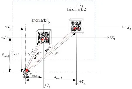
Fig.2 Specific landmark calculation
It is known that the QR code landmark contains its absolute position information relative to the world coordinate system. By calculating the rotation vectorRand the translation vectorTof the robot relative to the center point of the QR code, the relative coordinates (xc-qr,yc-qr,zc-qr) of the robot in the QR code coordinate system are obtained. By using the absolute position of the QR code landmark relative to the world coordinate system and the relative position of the robot relative to the QR code, the real-time position of the robot can be accurately calculated without the need for scene presets. It has certain scene versatility and can be widely used.
The main work of this paper is shown in Fig.3. Firstly, we complete the data definition in the landmark and the preprocessing of robot-captured images. Then, according to the coordinates of the robot relative to the world coordinate system with the center of the landmark as the origin, we calculate and thus obtain the absolute position(xqr1,yqr1) of the robot through the division principle conversion between the world coordinates and the absolute coordinates (xrobot1,yrobot1) of the robot to the landmark in the working environment. In the state of multiple landmarks, the final position (xrobot,t,yrobot,t)of the robot is calculated by assigning different weights to the depth of the relative landmarks. Finally, the orientationθof the current robot is calculated based on different positions at adjacent times. Location information,e.g.(355 cm, 455 cm), represents absolute coordinates in the working environment, while orientation data include orientation and specific angles,e.g.35° northeast.
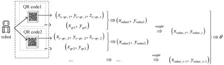
Fig.3 Main work of this paper
1 Experiments
1.1 Camera calibration
Whether it is three-dimensional reconstruction or machine vision applications, the calibration accuracy of camera parameters directly affects the accuracy of the final calculation, so the completion of the camera calibration is the premise and basis for accurate image calculation. The purpose of the camera calibration is to obtain the internal and external parameters of the camera, correct the captured image and then obtain the image with less distortion for calculation to improve the accuracy. In this paper, Zhang’s calibration method[11]and 8×5 Aruco code are used to estimate the internal and external parameters of the camera. Compared with checkerboard calibration, Aruco calibration[12]is more accurate.
1.2 Image preprocessing
For the acquired image, image preprocessing is needed. Due to the variability of the robot’s working scene, it is necessary to quickly complete the positioning of the QR code landmark. We use the software Zbar to extract the feature points of the QR code landmark and analyze the data.
Firstly, the image is preprocessed, and the software OpenCv and Zbar are combined to complete the data recognition and feature point extraction of the QR code[13]. Compared with the RGB image, the binary gradient of the QR code is more obvious and convenient for processing. The image is subjected to grayscale conversion, Gaussian smoothing filtering, median filtering, edge detection, binarization, closed operation and expansion processing, and thus the rectangular boundary of the QR code is found to store the image variable. Software Zbar is used to scan the row and column pixels of the variable to analyze the data and the feature points. In this paper, the QR code contains data including the size of the QR code, the coordinates of the QR code landmark in the world coordinate system, the partition where the QR code landmark is located, and the identification (id) of the QR code landmark.
Secondly, the classification is based on whether the landmark size in the QR code landmark to be identified is known. If the size of the QR code landmark is known, the absolute position of the robot can be calculated regardless of the single landmark and multiple landmarks. For such a landmark, only the feature points of the QR code landmark need to be combined and stored in a one-to-one correspondence between the two-dimensional(2D) pixel coordinates and the three-dimensional(3D) world coordinates. If the size of the QR code landmark is unknown, the calculation of the robot cannot be completed when there is only a single landmark in the robot view. When there are multiple landmarks, the feature points can be extracted, converted and stored after the size calculation is completed.
If there are multiple QR codes in the image captured by the robot and the size is unknown, it is necessary to calculate the ratio of pixels to the actual distance according to the adjacent QR codes. After the calculation of the ratio is completed, the actual size of the QR code landmark is calculated, and then the extraction of the combined feature points is completed. First of all, assuming that the size of theith QR code landmark is unknown, according to the (i-1)th QR code landmark, the absolute position of theith QR code landmark is identified as (px, i,py, i), and the absolute position of the (i-1)th QR code landmark is (px, i-1,py, i-1). The difference in theXandYdirections of the absolute position corresponds to the pixel difference of the same point of the QR code landmark, according to the coordinates of the QR code,i.e.the pixel difference of the four feature points of the upper left (x0,y0), the lower left (x1,y1), the upper right (x2,y2), and the lower right (x3,y3). The pixel differencesxagvandyagvin theXandYdirections are calculated, respectively.
(1)
(2)
wherejrepresents the direction sign on the QR code landmark.
According to the differences betweenxagv,yagvand the absolute position (px,i,py,i), the unit conversion ratio of the pixel to the actual distance is calculated. The ratioslxandlyin theXandYdirections and the average ratiolagvare expressed as
(3)
(4)
(5)
After calculating the proportion, for the QR code with an unknown landmark size, the actual size can be transformed according to the pixel differences of the QR code in theXandYdirections. The shooting angle of the robot may cause the horizontal or vertical pixel visual compression of the points on the landmark in the image. So for the accuracy rate, it is necessary to take the average pixel differencesxpandypof theXandYcoordinates first.
(6)
(7)
wherex0,x1,x2andx3represent the abscissa of the four feature points of the QR code;y0,y1,y2andy3represent the ordinate of the four feature points of the QR code.
According to the average value of the actual distance of the QR code, the sizeLof the QR code can be expressed asL=lagv×(xp+yp)/2. The world coordinate system is established with the center of the QR code landmark, where the depth of thez-axis is 0, and the 3D coordinate of the upper left corner is (-L/2, -L/2, 0).The remaining feature points can be calculated by the size and correspond to the 2D feature points one by one.
1.3 Position calculation based on QR code landmark
1.3.1QRcoderelativeposecalculation
To calculate the accurate pose of the robot relative to the QR code, the internal and external parameters of the camera are calculated according to the camera calibration method mentioned in section 1.1. When the image is obtained, the extraction of the image feature points and the extraction of the QR code data are completed. The known QR code feature point 2D coordinates and QR code size can complete the mapping of 2D coordinates and 3D coordinates, and then turn into EPnP[14]problem to solve the translation vector and the rotation vector of the robot relative to the QR code.
It is known that the transformation formula between the world coordinate system and the camera coordinate system isPc=R×Po+T, wherePcis defined as the point value of the camera coordinate system,Pois defined as the point value of the world coordinate system, and the matricesRandTare the transformation parameters of the world coordinate system and the camera coordinate system, respectively.
In this paper, it is assumed thatPcis the center point of the QR code landmark, and the coordinate ofPcis (0,0, 0). Then the coordinatePoof the robot can be obtained by the rotation translation vector, that is,Po=-R-1+T. When the coordinates of the robot relative to the QR code landmark and the data contained in the QR code are known, the absolute position of the QR code can be calculated. The diagram for scene partition and landmark placement is shown in Fig.4. Four partitions are delineated by angles.

Fig.4 Scene partition and landmark placement diagram
The calculation method of the relative pose and actual position of the robot is determined according to different partition principles when the landmark is placed.
1.3.2Conversionofrelativeposeandactualposition
When the coordinates of the robot relative to the QR code landmark are calculated, the relative position of the robot and the QR code landmark is determined, and the data format contained in the QR code landmark is specified as {id: 1; position x: 40; position y: 20; part: 1; size: 14 cm}. When the absolute position of the robot is calculated, appropriate adjustments need to be made based on the partition currently in the actual scene.
As shown in Fig.5, the robot combines its world coordinates relative to the landmark and the absolute position of the landmark to obtain the absolute position of the robot. It is assumed that the absolute position coordinatepc-qrof the robot is (xrobot,yrobot), the world coordinatepc-qrof the robot relative to the QR code is (xc-qr,yc-qr,zc-qr), and the absolute positionpqrof the QR code itself is(xqr,yqr). The partitions of different landmarks are different, so the conversion betweenpc-qrandpqris also different. According to the partition shown in Fig.4, we set the partition principle as follows.
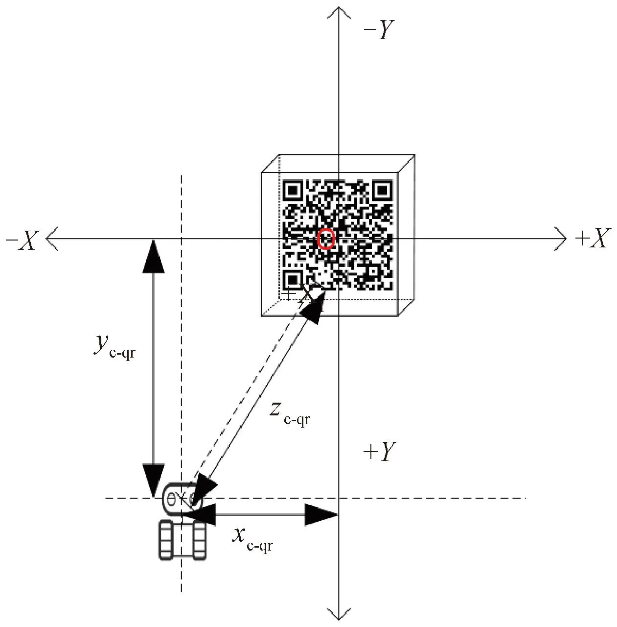
Fig.5 Robot coordinates in QR code landmarks
Partition l:Probot=(xqr+zc-qr,yqr-xc-qr).
(8)
Partition 2:Probot=(xqr+xc-qr,yqr+zc-qr).
(9)
Partition 3:Probot=(xqr-zc-qr,yqr+xc-qr).
(10)
Partition 4:Probot=(xqr-xc-qr,yqr+zc-qr).
(11)
We select different conversion principles based on the part field contained in the landmark to complete the robot position calculation.
1.3.3Analysisofcalculatedvaluesundersinglelandmarkandmultiplelandmarks
Under the condition of the known QR code landmark size, if the current robot vision contains only one identifiable QR code landmark, the relative pose is calculated directly according to the landmark and then the absolute position is calculated.
If there arenQR code landmarks, the absolute pose of the robot based on a single landmark is calculated for each of thenQR code landmarks, and the distance is sorted according to the depth of the robot determined by the world coordinate system of different QR code landmark centers. The absolute pose of the robot calculated by the nearest QR code landmark is assigned a higher weightW, and the weight decreases as the distance increases. The final absolute position (Xreal,Yreal) and the position angleθof the robot are calculated by the comprehensive weight as follows.
(12)
(13)
(14)
whereXcal, j(j= 1, 2, …,n) andXcal, m(m= 1, 2, …,n) represent the absolute positionXof the robot calculated according to thejth ormth label, respectively;Ycal, j(j= 1, 2, …,n) andYcal, m(m= 1, 2, …,n) represent the absolute positionYof the robot calculated according to thejth ormth label, respectively. We combineθwith the positive and negative differences of different positions at adjacent moments to determine the orientation of the robot.
2 Results and Discussion
We divide the robot’s working area as shown in Fig.4 of section 1.3.1. The images captured by the robot in multiple landmark states are shown in Fig.6. According to the landmark in the field, the pose is calculated, and then the actual value and the calculated value are analyzed and compared by random sampling, which mainly involves the consistency analysis of the same position based on different landmarks, the comparison between the calculated value and the actual value of the robot position, and the accuracy analysis of the robot orientation under multiple landmarks.

Fig.6 Images captured by robot in multiple landmark states
2.1 Calculation of the same position by different landmarks
In the case where there are multiple landmarks in the field of view, it is necessary to ensure that the robot maintains a certain uniformity in the calculation position under multiple landmarks. The world coordinate system of the robot relative to the center point of the QR code and the estimated position of the robot are shown in Fig.7.
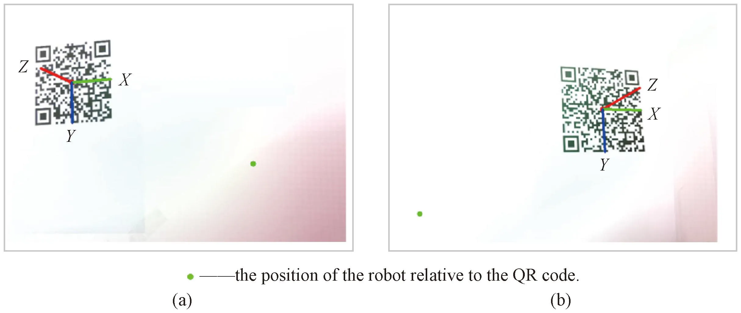
Fig.7 World coordinate system: (a) robot on the right of the QR code; (b) robot on the left of the QR code
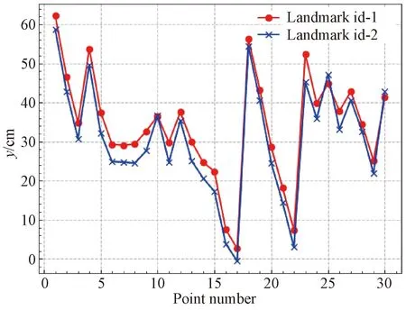
Fig.8 Judgment of the same position based on different landmarks in Y direction
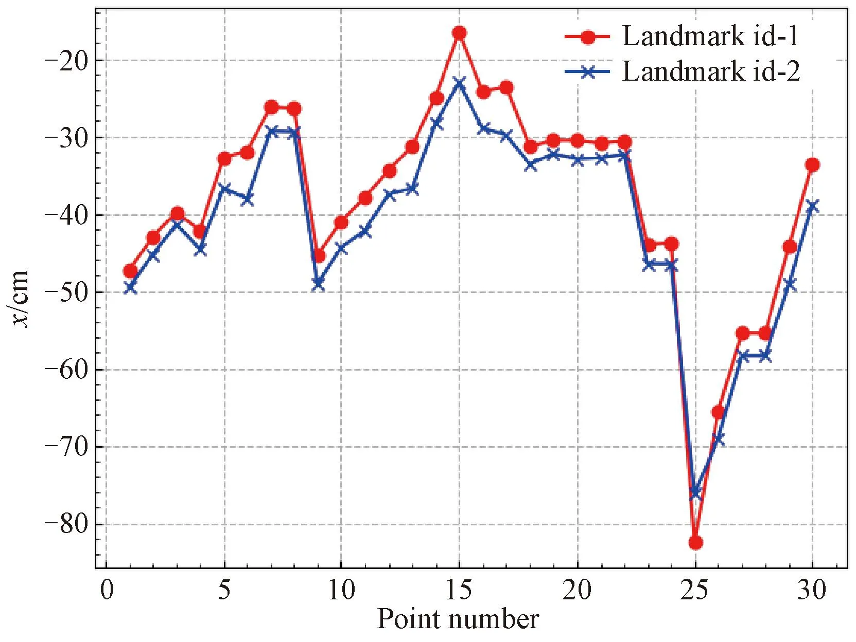
Fig.9 Judgment of the same position based on different landmarks in X direction

Fig.10 Comparison of the calculated value and real value of robot coordinates relative to the QR code landmark: (a) in X direction; (b) in Y direction
The experimental data containing multiple landmarks are randomly selected to calculate the final position of the data for analysis. For the judgment of the same position based on different landmarks (id-1 and id-2), the experimental results are statistically shown in Figs. 8 and 9. It can be seen that the robot’s calculation trend for multiple landmarks is consistent. The overall calculated value of the id-1 landmark is higher than that of the id-2 landmark. The relative error of theXposition is about 2 cm, and the relative error of theYposition is about 4 cm. Based on the different depths of the robot relative to the QR code landmark, the relative error calculation in different directions is also inconsistent. Due to the different depths of robots based on different landmarks, the measurements of different landmarks at the same position have different results, and thus there are certain errors which need to be balanced by the law that the depth is inversely proportional to the weight.
2.2 Multiple landmarks calculated and actual position values
For the position calculation of a single landmark, the final position result of the robot is based on the calculation result of a single landmark, while for the position calculation of multiple landmarks, the final position result needs to be calculated by assigning different weights according to the depth of the relative QR code. The calculation results of the robot relative to the QR code landmark are randomly selected to analyze and verify the calculation accuracy compared with the real results, shown in Fig. 10.
For the calculation of multiple QR code landmarks, the average calculation time of robot position measurement based on two QR code landmarks in the field of view shown in Fig.6 is about 0.3 s. In theXdirection, the relative error of the data is 4.320 2 cm, and the maximum error is 3.710 8 cm. In theYdirection, the relative error of the average data is 2.074 6 cm, and the maximum error is 3.069 6 cm.
2.3 Orientation analysis of relative QR code landmark
In the previous work, we calculated the absolute position of the robot. We obtained the specific data of the robot orientation by calculating the different positions of the adjacent moments. We calculated the angle data in the orientation of the robot by the inverse tangent of the position difference between adjacent moments and then judged the four directions of east, south, west and north according to the positive and negative coordinate difference. In this paper, the negative value of the difference in theXdirection is defined as west and the positive value as east. The negative value of the difference in theYdirection is defined as south and the positive value as north. The typical orientation information of the robot is listed in Table 1, and the comparison of the calculated value and the real value of the robot orientation angle is shown in Fig.11.

Fig.11 Comparison of the calculated value and real value of robot orientation angle
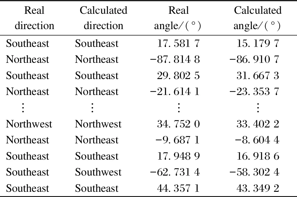
Table 1 Orientation information of robot
As shown in Table 1, the orientation information about the robot includes specific directions and angles. The maximum difference between the real value and the calculated value is 6.650 6°, the minimum difference is 2.677 2°, and the average difference is 0.003 3°. During the movement of the robot, if multiple QR code landmarks appear in the robot’s field of view, these QR code landmarks cannot equally divide the robot’s field of view. Therefore, during the calculation process, the closer the QR code is, the more accurate the calculation will be. At the same time, there is a maximum error due to the chance of equal field of view, but from the average error point of view, the calculation is still relatively accurate.
2.4 Application of this algorithm in practical engineering
The application of this algorithm in practical engineering is shown in Fig.12. We tested two kinds of road conditions, namely, flat roads and bumpy roads.
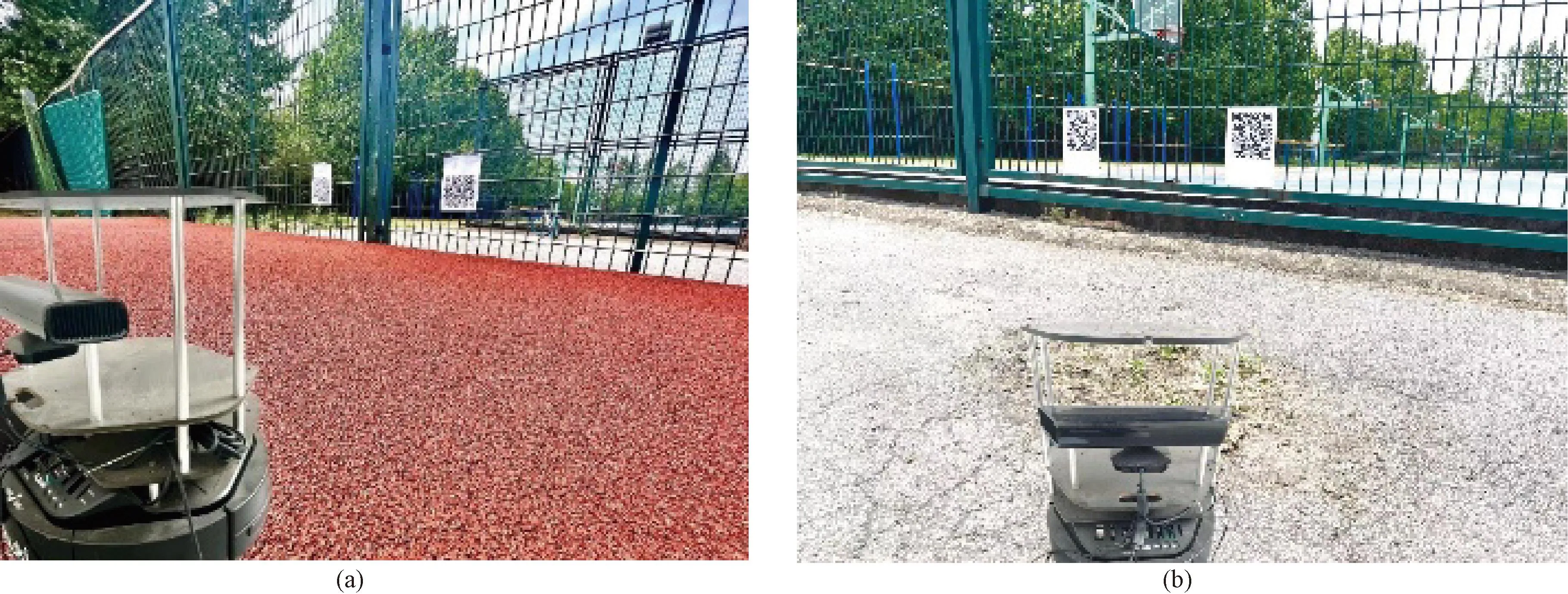
Fig.12 Application of the proposed algorithm in practical engineering: (a) flat road; (b) bumpy road
The test data are shown in Tables 2 and 3. During the calculation process, the calculation time of positioning data in different states was measured. When the road surface is flat, the average calculation cycle of the robot is about 0.35 s. When the road surface is uneven, the calculation cycle is relatively slow, namely 0.55 s. Based on the data in Tables 1-3, it can be concluded that the positioning calculation proposed in this paper has certain rationality in actual engineering.
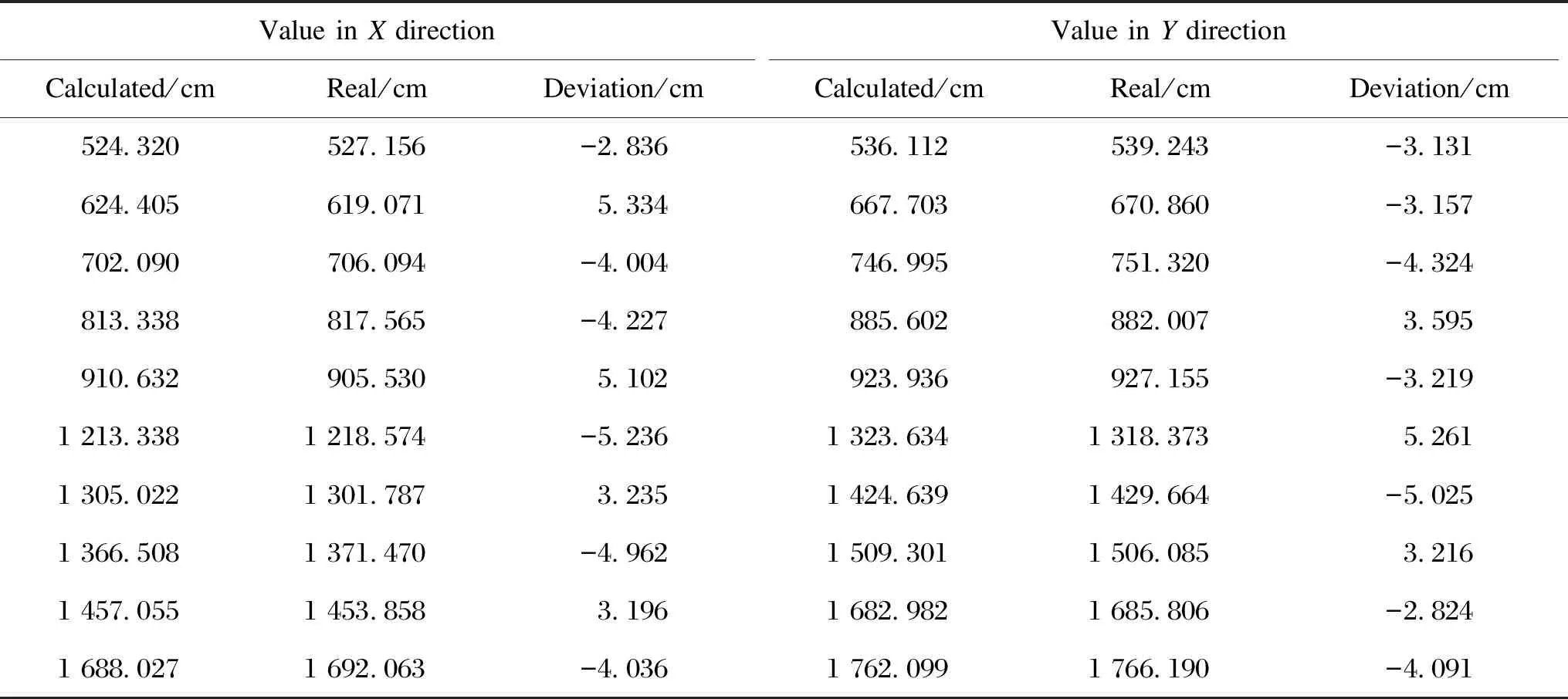
Table 2 Experimental data of flat road
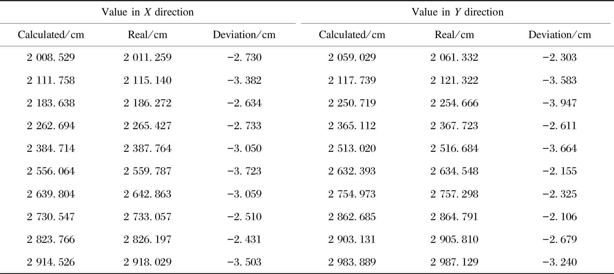
Table 3 Experimental data of bumpy road
3 Conclusions
In this paper, a robot positioning method based on multiple QR landmarks is proposed. Through the identification of the QR code data and the extraction of feature points, the robot’s position in the world coordinate system of the QR code is converted to the actual position. From the comprehensive analysis of the error of robot position calculation in the state of single and multiple QR code landmarks, compared with the traditional positioning methods based on QR code scanning, this method can complete the current accurate positioning and angle calculation of the robot. Compared with traditional electromagnetic navigation, inertial navigation and other navigation algorithms, this method presents the characteristics of low costs and strong environmental adaptability.
杂志排行

Journal of Donghua University(English Edition)的其它文章
- Recent Progress on Fabrication of Thermal Conductive Aluminum Nitride Fibers
- Cleaning of Multi-Source Uncertain Time Series Data Based on PageRank
- Deep Multi-Module Based Language Priors Mitigation Model for Visual Question Answering
- Detection of Residual Yarn in Bobbin Based on Odd Partial Gabor Filter and Multi-Color Space Hierarchical Clustering
- Electromagnetic and Thermal Characteristics of Molybdenite Concentrate in Microwave Field
- Path Planning of UAV by Combing Improved Ant Colony System and Dynamic Window Algorithm