Characterizations on the instantaneously formed Ni-containing intermetallics in magnesium alloys
2023-11-18ShuhuiLvQingYngFnzhiMengJinMeng
Shuhui Lv, Qing Yng, Fnzhi Meng, Jin Meng
a School of Materials Science and Engineering, Changchun University of Science and Technology 130022, PR China
b State Key Laboratory of Rare Earth Resource Utilization, Changchun Institute of Applied Chemistry, Chinese Academy of Sciences, Changchun 130022, PR China
Received 15 July 2021; received in revised form 22 October 2021; accepted 29 November 2021
Available online 27 January 2022
Abstract Instantaneous reactions of Al, Mn, Zn, Zr and Y with Ni by mixing the prepared Mg-8Al-0.4Mn, Mg-6Zn-2Y-0.5Zr and Mg-0.6Ni melts were investigated in this work to reveal the underlying mechanisms of their effects on the removal of Ni impurity. The results indicate three Ni-containing intermetallics, namely Al4NiY, Al4Ni(Y,Zr) and Al31Ni2Mn6. The former two phases present lath-like and have a relatively larger size (> 20 μm in length) than the latest one which is granular with the diameter of ∼120 nm. This illustrates that Al and Y(/Zr)can efficiently remove Ni by forming Al4NiY or Al4Ni(Y,Zr) which would precipitate to the bottom of the melt. Furthermore, adding Y into Mg-Al based alloys can simultaneously remove Fe and Ni, which contributes their excellent corrosion resistance. Finally, this paper proposes two methods helped to efficiently remove Ni for both Mg-Al based alloys and Al-free Mg alloys, and both of them are also benefit to improve alloys’ strength.
Keywords: Magnesium alloys; Intermetallics; Nickel; Transmission electron microscopy (TEM); Impurity.
1. Introduction
Magnesium alloys are strong candidates for existing and emerging engineering applications because of their light weight and high strength-to-weight ratio [1–3]. However,magnesium is anodic to most other metals due to its strongly negative electrode potential in aqueous environment, thus being prone to galvanic corrosion and finally exhibiting poor corrosion properties [4]. This greatly limits the usage of magnesium-based materials [4,5]. Therefore, many researchers have been paying attention to accomplish excellent corrosion properties of current magnesium alloys [4–9]. One prerequisite is careful control of the impurity levels, particularly Fe, Ni and Cu [4,10-13]. It is revealed that Fe and Ni are significantly detrimental to corrosion resistance of magnesium alloys and clearly increase the oxidation tendency of magnesium alloy melt. Thus, strict specification limits of<50 ppm apply in ASTM Standard and EU Standard [14,15].
To date,several effective methods of removing Fe impurity from magnesium alloys, such as by adding alloying elements which can react with Fe in magnesium melts to form highdensity intermetallic particles, have been reported [6,10,15-18]. With respect to the Mg-Al system, Mn addition was widely adopted to combat Fe impurity [4,19,20]. Zeng et al.[20] thoroughly studied the nucleation and growth crystallography of Al8Mn5on B2-Al(Mn,Fe) in AZ91 (Mg-9Al-1 Zn,wt.%) alloys and reported that at low Fe:Mn ratio, most Fe impurity is dissolved in B2 particles encapsulated by Al8Mn5which has low Fe concentration. This is important for alloys’corrosion resistance. Afterwards, Kim et al. [15] reported that very small amounts of Y addition can clearly reduce the Fe concentration level in a Mg-3Al alloy. Detailed examination illustrates that the added Y reacts with Fe impurity to form an Al8Fe4Y phase which owns much higher formation temperature than the Al8(Mn,Fe)5phase and results in the settlement of many particles to the bottom of the melting crucible. Recently, Yang et al. [19] found that Fe could be incorporated into some Mn-containing particles in a Mg-Mn based alloy with free Al addition, thus decreasing Fe solid-solute level in Mg matrix, and finally improving the alloy’s corrosion resistance.
During the process of removing Fe impurity by Mn addition, some Ni can also be removed. However, there are hitherto few efficient methods to purify contaminated metal to levels below high purity specifications in controlling Ni and Cu impurities [4]. Compared with Cu impurity, the level of Ni impurity is significantly detrimental to alloys’ corrosion properties[4,14].Although many researchers have studied the effect of Ni on microstructures and mechanical properties of various magnesium systems [21–24], the interaction between Ni and the common alloying elements is still unclear. To establish efficient methods to remove Ni impurity,it is therefore significant to investigate the instantaneous reactions between Ni and the common alloying elements in magnesium alloys such as Al, Mn, Zn, Zr and Y.
2. Experimental procedures
The studied alloy was fabricated from pure (99.9 wt.%)Mg, (99.9 wt.%) Zn, pure Al (99.9 wt.%), Mg-2 wt.% Mn,Mg-30 wt.% Zr and Mg-0.6 wt.% Ni master alloys. To avoid oxidation as can as possible, all raw materials were polished by power wire brush, then put into a steel crucible and blew by the protection mixed gas of CO2+ 0.8 vol.% SF6for∼30 min before heating. Finally, all raw materials were electrically melted in a steel crucible with three antrums marked by A to C and protected by the protection atmosphere. These three antrums correspond to three uniform-weight alloys with individual nominal chemical compositions: Mg-8Al-0.4Mn in A, Mg-6Zn-2Y-0.5Zr in B, and Mg-0.6Ni in C (wt.%). The corresponding schematic diagram is shown in Fig. 1a. Then,after removing the surface oxide layer, these three melts were simultaneously poured into a water-cooling iron mold with the diameter and length of ∼92 mm and ∼800 mm, respectively, when their temperatures were ∼700 °C. Finally,the chemical composition of the obtained ingot was determined through inductivity coupled plasma atomic emission spectroscopy (ICP-AES) and the concentration of oxygen was examined using the Oxygen-nitrogen-hydrogen analyzer(Bruker, G8 GALILEO), with the atmosphere of high purity helium and the decomposition temperature of ∼1200 °C.
Microstructures were characterized using optical microscopy (OM, Olympus-GX71), X-ray diffractometer (XRD,Bruker D8 FOCUS) with Cu Kαradiation (λ= 0.15406 nm)at 40 kV and 40 mA, backscatter scanning electron microscopy (SEM, Hitachi S-4800) equipped with energy dispersive X-ray spectroscopy (EDS) operated at 20 kV, and transmission electron microscopy (TEM, FEI Tecnai G2F20)equipped with EDS operated at 200 kV. OM and SEM specimens were firstly polished with Al2O3suspension after grinded using various SiC papers. Then, they were slightlyetched by a mixture of 5 mL acetic acid, 5 g picric acid,10 mL H2O, and 100 mL ethanol. Discs with diameter of 3 mm for TEM observations were cut with a thickness of 0.5 mm using wire cutting machine, then ground to a thickness of 25 ± 5 μm, and finally ion-milled using a Gatan Precision Ion Polishing System (PIPS) in the Ar ion-beam thinning process and cooled by liquid nitrogen, with voltage and current being set as 4.5 eV and ∼25 μA, respectively.Cylinder specimens with the size ofΦ6 mm × 12 mm were cut and machined from the as-cast ingot. Uniaxial compression test was performed at room temperature using the Instron 5869 testing machine, and the initial strain rate was set to be 0.001s-1.

Table 1 SEM-EDS analysis results of points A to F shown in Fig. 1c in at.%.
3. Results and discussion
The chemical composition of the obtained ingot was measured to be Mg-2.51Al-1.96Zn-0.62Y-0.11Mn-0.18Zr-0.14Ni(impurity: 0.0036 Si and 0.0021 Fe, wt.%). Fig. 1b presents a representative curve of the decomposed oxygen quantity against the analysis time measured by the Oxygen-nitrogenhydrogen analyzer. The oxygen concentration in the studied alloy is very low (<0.006 wt.%). Thus, we can regard it to be oxidation free. Fig. 1c shows an OM image of the studied alloy. Many intermetallic particles intricately distribute in theα-Mg matrix, which is significantly different from the typical microstructures (intermetallic particles distributing at grain boundaries and/or well-defined eutectic regions) of the traditional Mg-Al and Mg-Zn-RE based alloys [25–29]. From the backscatter SEM image (Fig. 1d), it can be seen that there are several kinds of intermetallic phases. To search the Nicontaining particles,EDS measurements at points A to F were performed and the analysis results are tabulated in Table 1.Three Ni-containing phases are revealed: the lath-like phase in Mg matrix (marked by B), the lath-like phase coexisted with the plate-like phase (marked by E), and the floriform phase (marked by D).

Fig. 1. (a) Schematic diagram of the cylinder crucible with three antrums and the alloy compositions in each antrum in this work, (b) curve of the decomposed oxygen quantity against the analysis time measured by the Oxygen-nitrogen-hydrogen analyzer, (c) OM and (d) backscatter SEM images of the studied alloy.
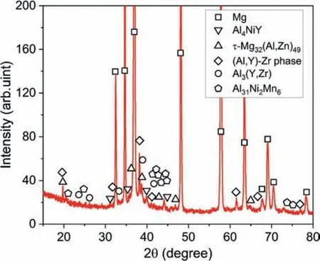
Fig. 2. XRD pattern of the Mg-2.51Al-1.96Zn-0.62Y-0.11Mn-0.18Zr-0.14Ni alloy.
Fig. 2 gives the XRD pattern of the studied alloy. Some relatively weak diffraction peaks from intermetallic phases were seen and can be indexed by Al4NiY,τ-Mg32(Al,Zn)49,Al3(Y,Zr), Al31Ni2Mn6and cubic (Al,Y)-Zr phases. This is reasonably consistent with SEM-EDS results which indicate multiple intermetallic phases. To further reveal the detailed structures and formation mechanisms of the Ni-containing intermetallic phases, TEM characterizations were conducted in the following. Fig. 3a shows a high-angle annular dark-field scanning TEM (HAADF-STEM) image of a lath-like phase along with EDS mappings of the added alloying elements for the region marked by a red dotted rectangle. Al, Y and Ni prefer to segregate in the lath-like phase while Al, Y and Zr, or Al and Zn in the attachment particles which can be seen clearly in the bright-field TEM image (Fig. 3b).The corresponding selected area electron diffraction (SAED)patterns from points A and B demonstrate that the lath-like phase is Al4NiY (tetragonal structure,a= 0.4057 nm,b= 1.5386 nm andc= 0.6634 nm [30]) and the adherent square phase is Al3(Y,Zr) (cubic structure,a= 0.4089 nm[31]). In addition, the Al3(Y,Zr) phase follows an identical orientation relationship (OR) with the Al4NiY phase as: (100)Al3(Y,Zr)//(021)Al4NiY, and [010]Al3(Y,Zr)//[100]Al4NiY.However, the corresponding high-resolution TEM (HRTEM)image (Fig. 3c) shows that the Al3(Y,Zr)/Al4NiY interface is unclear, forming an irregular mushy region (highlighted by green dotted lines). This might be attributed to the relatively large mismatch (∼19%) between the matching planes.
Fig. 4a presents a HAADF-STEM image of the lathlike phase embedded in a plat-like phase, forming a webfooted structure. According to the corresponding EDS mappings of the region marked by a red dotted rectangle, this embedded lath-like phase is enriched with Al, Ni, Y and Zr, which is different from the above lath-like phase. Nevertheless, the corresponding SAED patterns (Fig. 4b-e) from points A and B demonstrate that the lath-like phase has almost the same crystal structure with the Al4NiY phase while the webbed phase isτ-Mg32(Al,Zn)49(face-centered cubic structure,a= 1.416 nm [32]). The corresponding TEM-EDS point analysis illustrates a chemical composition of Mg4.79Al61.54Ni16.28Y6.65Zr9.49Mn0.87Zn0.38, which is reasonably consistent with the result of point E in Table 1.As a result, this embedded lath-like phase should be labeled as Al4Ni(Y,Zr). Based on many SAED pattern observations, no certain OR was found between Al4Ni(Y,Zr) andτ-Mg32(Al,Zn)49.
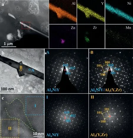
Fig. 3. (a) HAADF-STEM image along with EDS mappings of the alloying elements for the lath-like phase, (b) BF-TEM image of the lath-like phase attached with small square particles and the corresponding SAED patterns from points A and B, and (c) HRTEM of the Al3(Y,Zr)/Al4NiY interface along with the FFT patterns from local regions highlighted by blue and orange dotted squares.
From Fig. 1d, it is obtained that the floriform phase also contains a small amount of Ni. Fig. 5a gives its HAADFSTEM image along with the EDS mappings. This phase has very rough surface and seems to be assembled by numerous small ultra-fine particles. In addition, it is obvious that Y and Zr prefer to segregate in the center of each branch while Ni and Mn on the surface while Al-segregation can be observed in both surface and center of each branch of the floriform phase. However, the Al-concentration is clearly higher near the surface. Based on many SAED pattern observations such as shown in Fig. 5b, the fine particles in the center are an Al-containing Y-Zr phase (labeled as (Al,Y)-Zr in this work,and cubic structure,a= 0.7406 nm [33]). Furthermore, some twinning double diffraction spots were observed in the SAED patterns such as marked by green circles in Fig. 5b. From the corresponding HRTEM image (Fig. 5c), two well-defined twin domains (T1 and T2) can be seen and are separated by aggregated planar faults (PFs) which also lead to some extra diffraction streaks such as marked by green arrows along the<111>(Al,Y)-Zrdirection. Fig. 5d shows the SAED pattern of a certain particle near the surface of the floriform phase. The result indicates that the Ni-containing phase is Al31Ni2Mn6(tetragonal structure,a=0.755 nm,b=2.38 nm andc= 1.25 nm [34]). Therefore, the floriform phase is consisted of two structures: the cubic (Al,Y)-Zr phase and the Al31Ni2Mn6phase.
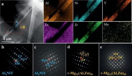
Fig. 4. (a) HAADF-STEM image of the embedded lath-like phase along with EDS mappings of the region marked by a red dotted rectangle, and the corresponding SAED patterns from points (b,c) A and (d,e) B.
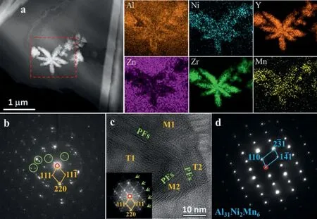
Fig. 5. (a) HAADF-STEM image of the embedded floriform phase along with EDS mappings of the region marked by a red dotted rectangle, (b) the SAED pattern from the center of a certain branch and (c) the corresponding HRTEM image of a (Al,Y)-Zr particle, and (d) the SAED pattern from the surface of a certain branch.
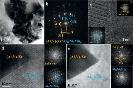
Fig. 6. (a) BF-TEM image and (b) SAED pattern of a Al31Ni2Mn6 particle embedded in the (Al,Y)-Zr phase, (c) HRTEM image of the Al31Ni2Mn6/(Al,Y)-Zr interface, and (d,e) HRTEM images of the same region with different view axes.
Generally, the Al31Ni2Mn6phase distributes near the surface of the floriform particle but is always embedded in the(Al,Y)-Zr phase,such as shown in Fig.6a.The corresponding SAED pattern (Fig. 6b) and HRTEM (Fig. 6c) observations indicate that the Al31Ni2Mn6phase follows a certain orientation relationship (OR) as (¯110)Al31Ni2Mn6//(1¯10)(Al,Y)-Zrand[¯115]Al31Ni2Mn6//[2¯1¯1](Al,Y)-Zr. The corresponding mismatch is approximately 8.4%. To identify whether the Al31Ni2Mn6phase nucleated in the (Al,Y)-Zr phase, further TEM examinations were conducted. Fig. 6d shows a HRTEM image where the Al31Ni2Mn6phase follows the same direction with that of Fig. 6c, but the (Al,Y)-Zr phase stands a random direction. In addition, stereographic projection analysis of the above OR indicate that the<101> axis of (Al,Y)-Zr is approximately parallel with<210>,<011>,<302>,or<012> axes of Al31Ni2Mn6. However, none was observed based on many TEM characterizations such as the HRTEM image shown in Fig. 6e. Therefore, the nucleation of Al31Ni2Mn6phase is probably related to the segregation of Ni and Mn elements which cannot be largely tolerated in the granular (Al,Y)-Zr particles or theτ-Mg32(Al,Zn)49matrix during solidification.
Based on the above analysis, there are three kinds of Nicontaining intermetallic phases, namely Al4NiY, Al4Ni(Y,Zr)and Al31Ni2Mn6, formed during instantaneous reaction, and the former two phases own relatively large size with the length over 20 μm while the last one is very fine with the diameter of ∼120 nm. This indicates a strong interaction between Al, Ni and Y (or Zr). Therefore, adding Al and Y/Zr is efficient to remove Ni impurity while adding Al and Mn has a much weaker effect on combatting Ni. Moreover, Zn seems to have no positive effect on removing Ni impurity. It is reported that Al would reduce the solubility of Ni considerably due to the formation of the AlNi phase [35], and if Mn is also added, the solubility of Ni decreased even further [36].In this work, no Al-Ni binary phase was found while an Al-Ni-Mn ternary phase, Al31Ni2Mn6, was frequently observed.This confirms that Al and Mn can remove Ni. Moreover, an American patent [37] presents a process for reducing the Ni content from ∼2% to ∼0.2% by Zr addition, and to 0.001%by Al and Zr addition. In this work, coarse Al4Ni(Y,Zr) particles were observed. Thus, the ultra-low Ni content in the Al and Zr containing alloy in Ref. [37] would be attributed to the formation of Al4NiZr which owns the same structure with Al4Ni(Y,Zr). Y addition improving the corrosion resistance of Mg-Al alloys was widely reported [4,15,38-42]. For example,Li et al. [38] reported that Y addition clearly improved the pitting resistance of an extruded AZ61 (Mg-6Al-1Zn-0.3Mn,wt%) alloy and Gang et al. [39] also stated that Y addition decreased the corrosion rate of a AZ31(Mg-3Al-0.8 Zn,wt%)alloy. Afterwards, Baek et al. [41] investigated the influence of 0.25 wt% Y on the corrosion rate of a Mg-6Al-1Zn-0.5Ca-0.3Mn alloy and pointed out that the Y addition changed the Al-containing intermetallic particles,thus improving corrosion resistance. Since appropriate Mn addition into Mg-Al alloys could reduce the Fe concentration below the critical level [4],the corrosion rate is slightly dependent on the Fe concentration. Also, excess Mn addition was also believed to reduce the Ni concentration in Mg-Al alloys, but the temperature is required to above 720 °C [14] and the removal ability is clearly lower than that of Y based on the results in this work.Therefore, Y addition improving corrosion resistance of Mg-Al alloys irrespective of Mn addition is also closely related to its effect on the removal of Ni impurity.
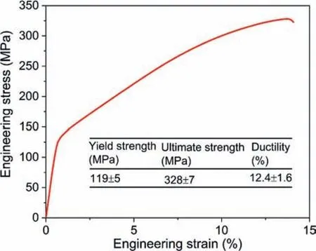
Fig. 7. Representative compressive engineering stress-strain curve of the ascast Mg-2.51Al-1.96Zn-0.62Y-0.11Mn-0.18Zr-0.14Ni alloy.
In traditional Mg-Al based alloys, Mn wad widely adopted to remove Fe [4,19,20,43], and this work indicates that Mn is less sufficient than Y in removing Ni. Recently, Kim et al.[15] pointed out that Y is also high-efficiency to remove Fe.Therefore, adding minor Y such as 0.2 - 0.4 wt.% Y into the traditional Mg-Al based alloys should be more efficient than adding 0.2 - 0.4 wt.% Mn to remove both Fe and Ni, thus to improve the alloys’ corrosion resistance. With respect to Alfree magnesium alloys, they generally own excellent mechanical performance [1,44-46]. However, because they are generally fabricated using the ordinary magnesium ingot, not high purity magnesium ingot, their Fe and Ni levels are in ranges of 15-80 ppm and 20-150 ppm, respectively, or even much higher [47,48]. Thus, they exhibit relatively poor corrosion resistance. In most cases, 0.3 - 0.6 wt.% Zr was added into these alloys for grain refinement [45]. Therefore, adding trace Al such as 0.01-0.2 wt.% is expected to be high-efficiency to remove Ni. Moreover, simultaneously adding minor Al and Y might be the most high-efficiency method to remove both Fe and Ni, thus improving alloys’ corrosion resistance, irrespective of whether they contain Zr.
From Fig. 1c and d, it is clear that there are several kinds of intermetallic particles having various morphologies. Particularly, there are a mass of floriform particles diffusely distributed in Mg matrix, which was rarely observed in the traditional Mg systems. To reveal the strengthening effect of these morphologically diverse particles on mechanical properties,the compressive curve of the studied alloy at room temperature is shown in Fig. 7. The corresponding compressive properties were summarized in the table inserted in Fig. 7.Generally, the yield strength, the ultimate strength and ductility in compression are 80 MPa, 340 MPa and 10%, respectively, for the traditional casting AZ80 (Mg-8Al-0.6 Zn,wt.%) alloy [49], and 93 MPa, 313 MPa and 18%, respectively, for the AZ91D alloy [50]. Thus, the studied alloy has much higher strength than and comparable ductility with the traditional Mg-Al based alloys [49–51]. This suggests that adding Y into Mg-Al based alloys and adding Al or Al and Y into the Al-free Mg alloys are also benefit to improve alloys’ strength.
4. Conclusion
In summary, instantaneous reactions of Al, Mn, Zn, Zr and Y in melt indicate that Al and Y/Zr will apace combine with the detrimental Ni impurity to form Al4NiY/Al4Ni(Y,Zr)intermetallics, which would precipitate to the bottom of the melt,thus reducing the soluble Ni content.As investigations dealing with the Al4NiY or Al4Ni(Y,Zr) phase have been rarely reported in magnesium alloys to date, the role of Al and Y/Zr in the removal of Ni from magnesium alloy melts still remain unclear. This work reveals the underlying mechanisms of the removal effect of adding Al and Y/Zr, and elaborates the underlying cause of why Y addition improves the corrosion resistance of Mg-Al alloys as its effect on the removal of both Fe and Ni. Finally, we propose two methods helped to efficiently remove Ni for both Mg-Al based alloys and Al-free Mg alloys, and indicate the studied alloy also exhibit excellent mechanical properties, and they are also benefit to improve alloys’ strength.
Declaration of competing interest
The authors declare that they have no known competing financial interests or personal relationships that could have appeared to influence the work reported in this paper.
Acknowledgments
This work was supported by the National Natural Science Foundation of China under grants no.11804030,the Scientific and Technological Developing Scheme of Jilin Province under grants no. 20200801048GH.
杂志排行
Journal of Magnesium and Alloys的其它文章
- Corrosion resistance of Mg-Al-LDH steam coating on AZ80 Mg alloy:Effects of citric acid pretreatment and intermetallic compounds
- Gradient structure induced simultaneous enhancement of strength and ductility in AZ31 Mg alloy with twin-twin interactions
- In-depth analysis of the influence of bio-silica filler (Didymosphenia geminata frustules) on the properties of Mg matrix composites
- Effect of Cd on matrix structure ordering and aging precipitation evolution in a Mg-Gd-Cd solid-solution alloy
- A multifunctional osteogenic system of ultrasonically spray deposited bone-active coatings on plasma-activated magnesium
- Rolling texture development in a dual-phase Mg-Li alloy: The role of temperature
