The role of melt cooling rate on the interface between 18R and Mg matrix in Mg97Zn1Y2 alloys
2023-11-18JinShoLiPengLvZhngLi
Q.Q. Jin, X.H. Sho, J.M. Li, Z.Z. Peng, M. Lv, B. Zhng, Y.M. Li, X.L. M
a
Materials Science and Engineering Research Center, Guangxi University of Science and Technology, Liuzhou 545006, China
b Shenyang National Laboratory for Materials Science, Institute of Metal Research, Chinese Academy of Sciences, Shenyang 110016, China
c School of Materials Science and Engineering, Hebei University of Science and Technology, Shijiazhuang, Hebei 050018, China
Received 6 May 2021; received in revised form 17 August 2021; accepted 5 November 2021
Available online 9 December 2021
Abstract The role of melt cooling rate on the interface morphology and dislocation configuration between 18R long-period stacking ordered (LPSO)structure and Mg matrix in Mg97Zn1Y2 (at.%) alloys was investigated by atomic-scale HAADF-STEM imaging. The 18R/Mg interface is step-like both in the near-equilibrium alloy and non-equilibrium alloy. Lower cooling rate makes the step size more regular and larger. Only 54R structure can be observed at the interface in the near-equilibrium alloy, and the dislocations are highly ordered. 54R and 54R′ structure sandwiched by b1 and b2 + b3 dislocation arrays, and new dislocation configuration can be detected at the interface in the non-equilibrium alloy, but the dislocations are less ordered. 18R/Mg interface containing 54R or 54R′ in equilibrium width, parallel to the (01¯10) plane,should be most stable based on elastic calculation. The segregation of solute atoms and its strong interaction with dislocations dominate the LPSO/Mg interface via diffusion-displacive transformation.
Keywords: Magnesium alloys; Long-period stacking ordered phases; Dislocations; Interface structure.
1. Introduction
Interfaces, such as twin boundaries, grain boundaries, and phase boundaries, have substantial influences on the behavior of polycrystalline solids [1–6]. For instance, the (111) coherent twin boundaries are known to be as effective as conventional grain boundaries in strengthening materials for facecentered cubic metals,but much more stable against migration for their lower excess energy [1–3]. The nucleation and migration of complex semi-coherent twin grain boundaries play a crucial role in the twinning and detwinning process [4–6].The phase boundaries in alloys are effective to block dislocation motion and crack propagation. The strength effect and migration behavior of phase boundaries are usually related to interfacial dislocations and segregation of solution atoms[7–10].
In the past decades, magnesium alloys containing longperiod stacking ordered (LPSO) structures have attracted considerable attention for their unique structural characteristics [11–20] and superior mechanical properties [21–24]. For example, the Mg97Zn1Y2(at.%) alloys exhibited high tensile yield strength both at ambient and elevated temperature[21,23],which is strongly related to the high intrinsic mechanical properties [25] and thermal stability of LPSO structures[21].It is necessary to study the formation and transformation of the long-period stacking ordered structures during heat treatment to order alloys containing LPSO structures, which has a great influence on damping and mechanical properties[26,27]. Usually, the migration of incoherent (01¯10) interface between LPSO structure and Mg matrix plays an important role in determining the growth and decomposition of the LPSO structures [28]. Investigating the boundary structure helps better understand the growth of LPSO structures and the stability of the interface and interpret their morphology. Previous works [28] have attempted to investigate the incoherent(01¯10) boundaries. However, no detailed structural information of interfacial dislocation configuration was provided,mainly because the boundaries are not sharp in the alloy solution treated at 500 °C and followed by water quenching.
We recently succeeded in obtaining sharp LPSO/Mg boundaries by fabricating Mg97Zn1Y2(at.%) alloys under the near-equilibrium condition [29]. We visualized that highly ordered complex incoherent 18R/Mg boundaries dissociated intob1dislocation array andb2+b3dislocation array with a slice of 54R sandwiched between them.The irregular 14H/Mg semi-coherent (SC) interface features alternately arrangement of two dislocations with an equal magnitude but opposite Burgers vectors. The behavior of the SC interfaces was dominated by the interaction between the dislocation pairs and solution atoms. In the present work, we will further unravel the role of melt cooling rate on the interface morphology and corresponding dislocation configurations between 18R and Mg matrix in the Mg97Zn1Y2(at.%) alloys.
2. Experimental
To investigate the characteristics of semi-coherent (SC)boundaries between 18R LPSO structures and Mg matrix,two Mg97Zn1Y2(at.%) alloys were prepared by melting high purity Mg, Zn, and Mg-30 wt.% Y master ingots in a resistance furnace, under a protective mixed gas of SF6(0.5 vol.%) and CO2(99.5 vol.%). The near-equilibrium alloy was obtained by cooling down to the room temperature in the furnace at 4 °C/min. The other non-equilibrium alloy was obtained by casting in a pre-heated graphite crucible mold under the protective gas. Thin foils for scanning transmission electron microscope (STEM) observations were cut from as-cast ingots, ground, and punched to a specific size with a diameter of 3 mm and thickness of 50 μm. They were firstly thinned by twin-jet electropolishing in a solution of 1% HClO4in ethanol under the conditions of 20 mA,35 V, and – 20 °C. They were then further thinned by low energy ion beams in a Gatan precision ion polishing system cooled by liquid nitrogen, with an incidence angle of 4°and voltages in the range of 3.5 ∼1.0 kV for 1 h. The high angle annular dark-field scanning transmission electron microscope (HAADF-STEM) imaging was performed by an aberration-corrected Titan3TMG260–300 scanning transmission electron microscope equipped with a high-brightness field-emission gun (X-FEG) and double Cs correctors from CEOS, operated at 300 kV. All the HAADF-STEM images in this work were recorded along [2¯1¯10]αzone axis.
3. Results and discussion
3.1. Interface between 18R and Mg matrix in a near-equilibrium alloy
We have observed and investigated 18R/Mg boundaries in the near-equilibrium Mg97Zn1Y2(at.%) alloy cooled in the furnace at 4 °C/min [29]. HAADF-STEM image in Fig. 1a shows that the interface between 18R structure and Mg matrix exhibits step-like morphology, and the size of the majority of the steps is several hundred nanometers. The step-like interface consists of (0001) coherent interface and (01¯10) semicoherent(SC)interface.HAADF-STEM image at higher magnification in Fig. 1b shows that one in three fringes extends into the Mg matrix, forming a highly ordered fence-shaped structure at the SC interface. The dissociation of the 18R/Mg interface into a pure edge dislocation (b1) array and a doublecore dislocation (b2+b3) array leads to the formation of a 54R structure. Theb1array in the 54R/Mg interface and the(b2+b3) array in the 54R/18R interface result in a tilt angle of the basal plane of 54R by 2.26° The interaction forces between the dislocations in each interface make the walls the most stable on the (01¯10) plane [29]. Thus, the step-shaped 18R/Mg boundaries can be observed in the near-equilibrium alloy, as is shown in Fig. 1a. Meanwhile, the interaction force between the two walls dominates the equilibrium width of 54R. The experimental width of the 54R in Fig. 1b varies in the range of 3.4 ∼7.8 nm and is larger than the evaluated equilibrium width (approximately 2.8 nm) [27].
3.2. Interface between 18R and Mg matrix in a non-equilibrium alloy
The microstructure of the non-equilibrium Mg97Zn1Y2(at.%) alloy cast in a graphite crucible mold was investigated in Figs. 2 and 3 to clarify the role of melt cooling rate on the interface morphology and interfacial dislocations configuration. A low-magnification HAADF-STEM micrograph provided by Fig. 2a presents the interface between 18R structure and Mg matrix. The interface features the irregular step-like morphology, and the size of each step is less than 100 nm.Fringes with a spacing ofy0= 6 ×d0002= 1.56 nm are readily observed in the 18R structure exhibiting bright contrast,while the Mg matrix exhibits dark contrast. One in three fringes extends into the Mg matrix, forming a new fenceshaped structure in the SC interfaces, which can also be determined as 54R. Besides, the spacing of some neighboring fringes extending into the matrix is 4y0, as is indicated by arrows. To identify the structure details of the front tips of 18R/Mg SC interfaces, an atomic-resolution image was obtained in Fig.2b.The interfacial dislocations were determined to be 30° and 90° Shockley partial dislocations by measuring their edge components via open rectangular rings. Five AB′C′A blocks extended into Mg matrix, and only two dislocations at the end of blocks 1 and 14 are 90° Shockley partial dislocations. Two dislocations at the end of blocks 7 and 10 extending into Mg matrix are 30° Shockley partial dislocations. The distorted region exists at the end of two neighboring blocks, such as blocks 4 and 5, blocks 8 and 9.The edge component of the Burgers vector of the dislocation at their ends indicates they are 30° partial dislocations.The dislocations at the end of the rest blocks are 30° partial dislocations. Interestingly, the sum of Burgers vectors of dislocations at the end of each block group (1, 2 and 3), (4, 5 and 6), (7, 8 and 9), (12, 13 and 14) is zero. The 30° dislocation at the end of block 4 and 5 can be dissociated into one 90° partial dislocation and one 30° partial dislocation,i.e., 30° →90° + 30° We can also argue that block 4 and 5 are exactly bounded by a 90° partial dislocation and a 30°partial dislocation, respectively, and their summation is the 30° partial dislocation. The dislocations at the end of blocks 1 and 2 show a similar pattern.
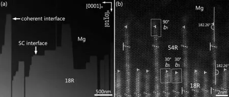
Fig. 1. (a) Low-magnification HAADF-STEM image showing the coherent and SC interface between 18R and Mg matrix in a near-equilibrium Mg97Zn1Y2 alloy. (b) HAADF-STEM image of the complex 18R/Mg SC interface at atomic scale, which is split into b1, b2 dislocation array and b3 dislocation array with a slap of 54R between them.
Fig. 3 investigated a novel interface structure between 18R and Mg matrix in the non-equilibrium Mg97Zn1Y2(at.%) alloy. The low-magnification HAADF-STEM image in Fig. 3a also presents a step-like interface, and each step is tens of nanometers in width. Surprisingly, two in three fringes extend into the Mg matrix, forming a new fence-shaped structure in the SC interfaces. An atomic-resolution HAADF-STEM image was obtained in Fig. 3b to identify its detailed structure character. Two AB′C′A building blocks in three of the 18R extended into the matrix periodically withb2andb3dislocations at their ends, forming a 54R′structure expressed as (F2F8)3[16]. It is interesting to note that the presence of 54R′leads to the decomposition of the 18R/Mg interface into 54R′/Mg and 18R/54R′tilt boundaries. The wall positioned at the 54R′/18R interface comprises pure edge (90°)Shockley partial dislocations with Burgers vectorb1equal tobobs= 1/3[0¯110]. Another wall consisting ofb2andb3is positioned at the 54R′/Mg interface, with both of their edge componentsb2eandb3eequal tobobs= 1/6[01¯10], suggesting they are mixed (30°) Shockley partial dislocations. The sign of their screw componentsb2sandb3scannot be determined from Fig. 1b. Our experiment proved that neither tilt angle nor twist angle between 18R and Mg matrix,suggesting the sum of both edge components and screw components ofb1,b2, andb3is zero. Thus, we can deduceb2= 1/3[10¯10]andb3= 1/3[¯1100] (orb2= 1/3[¯1100] andb3= 1/3[10¯10])with their screw components of opposite sign. Based on our previous estimation [29], the two walls with theb1,b2, andb3alternative arrangement will be most stable. Accordingly,the dislocation configuration at the 54R′/Mg and 18R/54R′interfaces lead to a 2.26° tilt angle along the basal plane of 54R′.
3.3. The role of elastic interaction on interface structure
The elastic forces acting on theb1,b2, andb3dislocations were calculated to interpret the morphology and the dislocation configuration of the complex boundaries. Fig. 4a present the forces on dislocationbqand a solute atom due to the stress field of dislocationbp. Fig. 4b,c presents the arrangement ofb1,b2, andb3dislocations responsible for the transformation from 18R/Mg SC interface into 54R and 54R’structure.Here,b1= 1/3[0¯110],b2= 1/3[10¯10], andb3= 1/3[¯1100]. Since the basal plane containing the dislocation line and its Burgers vector is the only slip plane for a Shockley partial dislocation inhcpMg structure, the component of forceFpq,x(noted asFpqin present work) along the slip direction betweenbpandbqdislocations is most important in determining the behavior of the dislocations in Fig. 4. The interaction forces and that contributed by their edge or screw components between two neighboring dislocations in each wall are plotted againstxin Fig. 4a in our previous work [29]. It follows thatb1array is most stable when the dislocations lie on the (01¯10) plane,leading to the formation of a low-angle tilt boundary in the 54R/Mg or 54R′/18R interface.The sum of Burgers vectors ofb2andb3is a pure edge dislocation with the same magnitude and opposite sense asb1.Such a double-core dislocation array is most stable when they lie on the (01¯10) plane forming a low-angle tilt boundary in the 54R/18R or 54R′/Mg interface.
We analyzed the equilibrium width of the 54R or 54R′structure via thermodynamics consideration of the complex boundaries with unit thickness, a length of 3ny0and a width ofω. The 54R with a width ofωcan be transformed from 1/3ω18R and 2/3ωMg via the repulse of two walls by a relative distance ofω, which can be expressed as:

Fig. 2. (a) Low-magnification and (b) Atomic-resolution HAADF-STEM images showing the irregular interface between 18R and Mg matrix in a nonequilibrium Mg97Zn1Y2 alloy cast in a graphite crucible mold. The dislocation configuration of the SC interface is illustrated in (b).
The 54R′with a width ofωcan be transformed from 2/3ω18R and 1/3ωMg via repulse of two walls by a relative distance ofω, which can be expressed as:
The interaction force betweenb1andb2(orb3) dislocations in two walls is
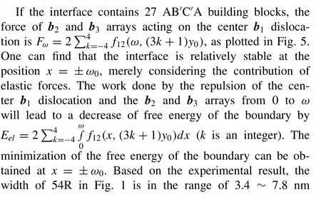

Fig. 3. (a) Low-magnification HAADF-STEM image showing a type of novel SC interface between 18R and Mg matrix in a non-equilibrium Mg97Zn1Y2 alloy cast in a graphite crucible mold. (b) Atomic-resolution HAADF-STEM images showing the complex 18R/Mg interface split into two dislocation arrays with a slap of 54R’ between them.
3.4. Cooling rate on the structure of interface structure
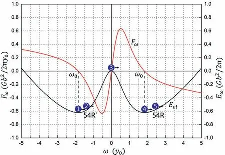
Fig. 5. Force considered for the b2 and b3 walls acting on the center b1 dislocation, and the role of free energy on the equilibrium width ω contributed by the interaction force, considering the interface contains 27 AB′C′A building blocks. The values of x and ω are expressed in units of y0, while the values of force and free energy are expressed in units of Gb2/2πy0 and Gb2/2π, respectively. The value of x with the positive and negative value presents the formation of 54R and 54R’ structure, respectively.
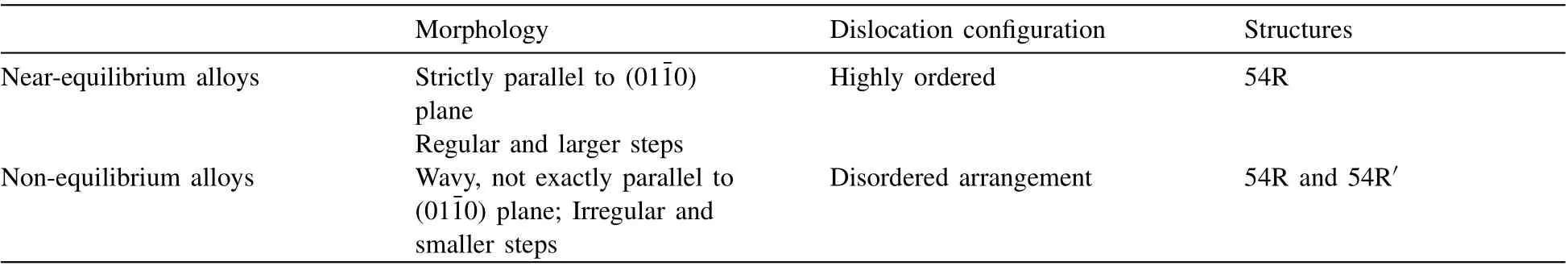
Table 1 The distinguished differences of the LPSO/Mgs non-equilibrium Mg97Zn1Y2 (at.%) alloys.
In this work, we investigated the SC interface between 18R and Mg matrix and calculated the elastic interaction between interfacial dislocations. Several distinguished characterizations could be concluded for the near-equilibrium and non-equilibrium Mg97Zn1Y2(at.%) alloys, as listed in Table 1. We’ll rationalize these from thermodynamics and dynamics. Firstly, ifb1,b2, andb3dislocations arrange ordered on the 18R/Mg interface, the sum of Burgers vector of dislocations at the end of any three neighboring building blocks is zero, which produces no macro strain. Theb1,b2, andb3dislocations arrange highly ordered in the SC interface in the near-equilibrium alloy, forming a perfect 54R structure, as shown in Fig. 1. Nevertheless, the disordered arrangement of dislocations and one Shockley partial dislocation at the end of two neighboring blocks can be occasionally observed in the SC interface in the non-equilibrium alloy, as shown in Figs. 2 and 3. Secondly, the dislocations on the 18R/Mg interface tend to split intob1dislocation array andb2+b3double-core dislocation array, because they are edge dislocations with Burgers vector of opposite signs. 54R or 54R’ formed on the 18R interface and the interface should be the most stable if their width is 1.8y0merely considering the elastic interaction between the two arrays, as shown in Fig. 5. Thirdly, based on the calculation of the elastic interaction F11betweenb1dislocations and F23betweenb2andb3dislocations (Fig 2c in Ref. [29]), the interface should be the most stable if theb1dislocation array andb2+b3dislocation array are strictly parallel to the (01¯10) plane. Experimentally,the dislocation array is strictly parallel to (01¯10) plane in the near-equilibrium alloy cooled in the furnace. Comparatively,the dislocation array is not strictly parallel to (01¯10) plane in the non-equilibrium alloy. Fourthly, the morphology of the interfaces is more regular and the size of the steps is larger in the near-equilibrium alloy than those in the non-equilibrium alloy. The dislocations on neighboring steps are not parallel to (01¯10) plane, thus more steps will result in higher interface energy. Formation of 18R/Mg SC interface with regular morphology strictly parallel to (01¯10) plane, a larger size of steps, and highly ordered dislocation configuration minimize the free energy of the interface. The alloy cooled at a lower rate will encounter a long-time high-temperature state, which should help the minimization of the free energy of the interface. Only 54R was observed in the SC interface between 18R structure and Mg matrix in the near-equilibrium alloy.In contrast, both 54R and 54R′structures were observed in the SC interface in the non-equilibrium alloy. However, both dislocation configurations in Fig. 4b and c are stable merely considering the elastic interaction between the two dislocation arrays. The phenomenon accounts for the better mobility of theb1dislocation and stronger interaction with solute atoms than theb2andb3dislocation.All the 54R′can transform into 54R during the long-time high-temperature state in the nearequilibrium alloy becauseb1dislocation can overcome the energy barrier. Part of 54R′was kept in the non-equilibrium alloy due to a higher cooling rate.
The cooling rate during fabrication has been proved to dominate the diffusion of solute atoms and the dislocation network during materials fabrication and heat treatment in steel and superalloys [7,30]. The formation of LPSO structures in Mg alloys is considered a diffusional-displacive transformation [31,32]. Y/Zn atomic clusters are expected to form first in the super-saturated Mg matrix followed by the formation of Y/Zn enriched GP zones on the basal planes of the Mg matrix. Above a critical amount of Y and Zn atoms in the GP zones, LPSO structures are formed from the GP zones by the generation and propagation of Shockley partial dislocations [32]. The Shockley partial dislocations are assumed to be triggered by the volume increase in the super-saturated Mg matrix owing to the Y/Zn clusters and the GP zone. That is, the amount of Y/Zn at the Mg matrix should be the key factor for the formation of LPSO structures. Therefore, the cooling rates that significantly affect the diffusion of solute atoms would lead to the formation of different interface morphology and dislocation configuration at the LPSO/Mg matrix interface.
4. Conclusion
We directly visualized the microstructure of interfaces between 18R and Mg matrix in near-equilibrium and nonequilibrium Mg97Zn1Y2(at.%) alloys to unravel the role of melt cooling rate on the interface morphology and the dislocation configuration. The main conclusions can be summarized as follows:
(1) Melt cooling rate plays a crucial role on the step-like interface of 18R LPSO structure. 18R/Mg interface consists of 54R structure under the lower cooling rate, while is composed of 54R and 54R′under higher cooling rate. The diffusion-displacive transformation dominates the interface of LPSO structures in Mg alloys.
(2) The presence of a 54R (or 54R′) structure leads to the dissociation of the 18R/Mg interface into two tilt boundaries. The pure edge dislocation (b1) array in the 54R/Mg(or 54R′/18R) interface and the double-core dislocation(b2+b3) array in the 54R/18R (or 54R′/Mg) interface lead to a tilt angle of basal plane of 54R (or 54R′) by 2.26°
(3) The interaction forces between the dislocations on each wall make the interfaces the most stable on the (01¯10)plane, and the interaction forces between the two dislocation walls affect the equilibrium width of 54R (or 54R′).
Acknowledgments
This work is supported by the National Natural Science Foundation of China(grant number 51801214 and 51871222),Guangxi Science and Technology Base and Talents Special Project (Guike AD20297034), Liaoning Provincial Natural Science Foundation (2019-MS-335), Research Start-up Funding from Guangxi University of Science and Technology (No.03200150), Natural Science Foundation of Hebei Province of China (grant number E2020208083).
杂志排行

Journal of Magnesium and Alloys的其它文章
- Characterizations on the instantaneously formed Ni-containing intermetallics in magnesium alloys
- Corrosion resistance of Mg-Al-LDH steam coating on AZ80 Mg alloy:Effects of citric acid pretreatment and intermetallic compounds
- Gradient structure induced simultaneous enhancement of strength and ductility in AZ31 Mg alloy with twin-twin interactions
- In-depth analysis of the influence of bio-silica filler (Didymosphenia geminata frustules) on the properties of Mg matrix composites
- Effect of Cd on matrix structure ordering and aging precipitation evolution in a Mg-Gd-Cd solid-solution alloy
- A multifunctional osteogenic system of ultrasonically spray deposited bone-active coatings on plasma-activated magnesium