Comparison between compression tested and simulated Mg-6.3Gd bone scaffolds produced by binder based additive manufacturing technique
2023-11-18MrtinWolffMohmmdMrviMshhdiEshwrNiddvoluHenrikneurgThomsEelRegineWillumeitmer
Mrtin Wolff, Mohmmd Mrvi-Mshhdi, Eshwr Niddvolu, Henrik Lüneurg,Thoms Eel, Regine Willumeit-Römer
a Institute of Metallic Biomaterials at Helmholtz-Zentrum Hereon, Max-Planck Str. 1, D-21502 Geesthacht, Germany
b Institute of Material Systems Modeling, Helmholtz-Zentrum Hereon, Max–Planck-Str. 1, 21502 Geesthacht, Germany
Received 10 February 2023; received in revised form 29 July 2023; accepted 13 August 2023
Available online 14 September 2023
Abstract In this study, a binder based 3D-printing technology viz. Fused Granular Fabrication (FGF) technique was used to produce interconnected and open porous Mg-6.3Gd bone scaffolds for compression test analyses. The consolidation of the green parts (as printed scaffolds) was performed using solvent debinding in cyclohexane and subsequent conventional sintering in argon atmosphere. Compression tests were performed on as sintered parts. Additionally, a simulation strategy was developed for modeling the compression behavior of the sintered parts,utilizing the data from the experimental results. The experimental compression test results and the simulation strategy for the compression behavior of the 3D-printed scaffolds demonstrated good agreement.
Keywords: Magnesium; Mg-6.3Gd; Additive manufacturing; Simulation; FGF; Biodegradable.
1. Introduction
Today, Additive Manufacturing (AM) of net-shape components by powder-based technologies is successfully applied on steel or other technical materials and even titanium. In particular for titanium,AM of medical implants individualized with respect to the patient´s requirements is commercially exploited,e.g. for the production of acetabula replacement or protheses in maxillofacial surgery [1–3]. However, the situation is different for magnesium alloys that are currently of high interest as materials for biodegradable implants like screws or bone plates. The high affinity to oxygen leads to the spontaneous formation of oxide layers on the magnesium powder particles by an exothermic process. Handling and processing of nonpassivated powders is difficult and can be even dangerous with respect to self-ignition of the powders. Commercially available Mg-powders are thus passivated by controlled oxidation of the surface as a part of the production process [4]. However,because of its brittle nature and a rather weak connection to the metallic bulk of the powder particle, the oxide layer can rather easily be disrupted, e.g. by mechanical treatments like sieving. Furthermore, the oxide layer remains stable up to the liquid phase formation at sintering temperature of the Mg-alloy and possible residuals in the microstructure after sintering have to be taken into account. AM technologies like powder bed fusion with laser (PBF-L) struggle with the handling of high volumes of unprotected magnesium powders and with the high vapor pressure of magnesium leading to smoke affecting the laser beam. Technical means like ventilation inside of the processing chamber can help and there has been some work on PBF-L of magnesium materials, summarized for instance in [5].
In general, alternatively to melting, sintering is applied for powder consolidation in a number of different technologies as Metal Injection Molding (MIM), Fused Filament Fabrication (FFF), Fused Granular Fabrication (FGF), Binder Jetting(BJ) and many more [6]. Again, steel and titanium powders are successfully processed by these techniques. Most of them work with a mixture of metal powders and polymeric binder as feedstock. This approach allows great flexibility with regard to the shaping process; almost all techniques suitable for polymers can also be applied to the powder-binder mixture.Binder based additive manufacturing techniques exclusively enable the production of hollow structured parts, even with a closed surface shell and generally without any need of depowdering, which is otherwise necessary in any powder bed based technique. For Mg-powders, usage of binder has the significant advantage that it protects the powder from contacting with air, thus, safety issues are significantly mitigated.Furthermore, in contrast to technologies involving melting,sintering creates typically very homogeneous microstructures being beneficial for isotropic properties and uniform degradation behavior. On the other side, the drawback is that the oxide layer acts as a severe obstacle for diffusion during sintering[7,8].There are few studies published about sintering of Mg-powders[9–11],some even with the purpose of AM techniques. In [12] a two step sintering process in combination with binder jetting is applied.However,the usage of additions like graphite powders and a rather difficult to control environment makes the process not applicable for biomedical applications where high purity material and reproducible properties are essential. On the other side, the authors of the present paper proved in several studies [13–21] that it is possible to apply successfully the common procedures of sintering-based AM if oxygen uptake during sintering is minimized and a partly liquid phase sintering process is applied. While most of the authors’ studies were performed on MIM, in this paper this knowledge is transferred to FGF as an additive technique for biomedical Mg-alloys. A first comparison of MIM and FGF for processing the technical alloy AZ41 was performed in [22]. Furthermore, one goal is to make a first step aiming at building a future digital twin of the implant, accompanying the real part from material production to application.
Binary MgGd alloys are well investigated as biodegradable metals for orthopedic implant applications and therefore a good standard for the study of novel processing techniques,test methods and simulation models [23–25]. Fused Granular Fabrication (FGF) and other AM techniques are very attractive with respect to the freedom in geometry and comparably low costs for production of individualized implants,produced using computer-tomography imaging in orthopedics and traumatology [26,27]. However, when using Ti or CoCralloys, their high strength and high stiffness requires these permanent implant materials to be removed after fractureand wound healing. Moreover, they suffer from stress shielding problematic and late inflammatory risks after implant removal. This causes additional stress and pain for the patent.In contrast, implants made of biodegradable metals with progressive degradation behavior enable orthopedic or traumatology surgical therapy without need of a second surgery for implant removal [28–31]. Especially, Mg-alloys can promote bone healing and stimulate bone formation [32]. However,fast degradation above 1 mm/year can cause subcutaneous gas bubble formation [33,34] or even an early implant failure. Hence, it is a challenge for complex and fragile implant structures or even porous scaffold structures to overcome this problem and enable mechanical stability of the scaffold for a certain time to enable safe wound healing and bone regrowth.
First trials with FGF revealed, that the macro pore size in as printed scaffolds (750 μm) is additional to the micro pores in the bulk structures of the sintered Mg-6.3Gd scaffolds and matches the typical criterion for bone scaffold materials.Murphy et.al. reported the optimal mean pore size for the best osteoblast proliferation to be 325 μm in collagen based scaffolds [35]. It is reported that a mixture of different pore sizes and permeability of scaffold can affect different cell migrations and cell interactions [36]. In MgP scaffolds, a mixture of micron sized pores (25 – 53 μm) and macro sized pores(300 μm) showed enhanced bone remodeling compared to scaffolds with only macro pores of 300 μm size [37]. Additionally, recent investigations on powder processed Mg-0.6Ca materials revealed that material porosities up to 10% do not negatively affect the degradation rates as long as the large fraction of pore diameters after sintering stays below 75 μm.The degradation rate values for these specimens were less than 0.3 mm/year this showed the possibility in obtaining robust degradation rates via powder processing technique [38].In the present study, the bulk strut of the material contains closed porosities lower than 5% and therefore similar robustness can be expected, however, this issue will be subject to further investigation.
The tailoring of such implant geometry by experimental trials is quite time consuming and expensive. Hence, successful simulation strategies and numerical methods are highly in need to support implant and scaffold design and experimental trials [39]. In this study, to the authors’ knowledge, for the first time worldwide, a binder based 3D printing approach using magnesium alloy Mg-6.3Gd was used for manufacturing of complex shaped open porous cubic bone scaffolds of nominal dimensions of high: 9.8 x width: 11.4 x depth: 11.4 mm3in the as sintered condition based on Body Centered Cubic(BCC) unit cell structure [40]. These macroscopic scaffold BCC unit cell strut structure was derived from the atomic BCC unit cell. The atomic BCC unit cell has atoms at each corner of the cube and an atom at the center of the structure. BCC materials are commonly used for their excellent mechanical properties, such as high strength, toughness and ductility than FCC (Face-centred Cubic) arrangements [41].
In order to perform FE simulation, it is necessary to know the mechanical behavior of the bulk material. According to former investigations on mechanical behavior of FGF and MIM fabricated materials, they behave quite similar mechanically[22].Hence,the mechanical properties were investigated using experimental compression testing of the sintered MIM-produced bulk material. The authors decided to use these MIM-data in numerical modeling. The experimental results were used for generation of a numerical simulation model of the compression behavior of the scaffold structure.Afterwards the material properties captured from experiments were compared to simulation results to verify the plausibility of the modeling strategy. The work should also clarify if the material properties of a sintered standard test specimen can be transferred to the thin structures of a strut made by FGF. If successful, this simulation model will be part of a future digital twin of the entire life cycle of an implant and supports the development of patient specific mechanical properties.

Table 1 Chemical composition of the MgGd alloy used in the present study. All values are indicated in wt%.
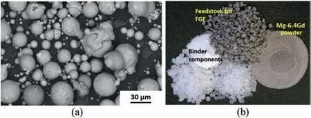
Fig. 1. (a) SEM-image of Mg-6.3Gd powder. (b). single binder components,Mg-6.3Gd powder and finished FGF-feedstock granules.
2. Materials and methods
2.1. Powder handling and feedstock praparation
For the specimen production, MgGa ingots were cast at Hereon and gas atomized by SFM, Martigny, Switzerland, resulting in Mg-6.3Gd powder as shown in Fig. 1a, spherical in shape and of size smaller 36 μm.To avoid any uptake of oxygen during later powder handling and processing, the highly oxygen affine powder was completely handled under protective argon atmosphere in a glovebox system(Unilab,MBraun,Germany). The chemical analysis of the powder with respect to alloying elements and contaminants influencing degradation properties, as there are Fe, Cu and Ni, using Inductively Coupled Plasma - Optical Emission Spectroscopy (ICP-OES,Spectro-Ametek, Acros II FHX22) is shown in Table 1.
Paraffin wax, stearic acid and polypropylene-copolymerpolyethylene binder components as listed in Table 2 and as shown in Fig. 1b were blended together with Mg-6.3Gd powder to prepare the feedstock for the 3D-printing approach. As a result from a previous optimization study, the powder loading of the 3D-printing feedstock was chosen to 55 vol% to enable failure free extrusion during printing. In comparison,the standard powder loading for MIM fabrication is 64 vol%.
During the entire sample preparation, high attention was laid on avoiding the contamination by iron or similar ele-ments that significantly deteriorate the degradation behavior.Consequently, the single organic binder components and the Mg-6.3Gd powder were placed in glass mixing beakers with magnesium lids as shown in Fig. 2a. The glass beakers with the feedstock were preheated for 90 min up to 175 °C in a furnace (Memmert, UF30plus, Germany) and homogenized in a planetary mixer by stirring the beakers for five minutes at 2000 rpm rotation speed (Thinky ARE 250 planetary mixer, Japan) as shown in Fig. 2b. The highly viscous feedstock was transferred to the glass-trays (see also Fig. 2a) and allowed to cool to room temperature. Subsequently, the solidified feedstock was granulated using a fully metal free jaw crusher equipped with zirconia plates (Fritsch, Pulverisette 1 classic line, Backenbrecher Modell 2, Germany) as shown in Fig. 2c. Finally, the granules were sieved into the size class of 2–6 mm diameter.

Table 2 Used binder components for MIM of Mg-6.3Gd.

Fig. 2. (a) Glass mixing beaker with Mg-lid and a glass cooling bowl. (b).Planetary mixer;yellow arrows point out the rotational parts. (c). Jaw crusher for the feedstock granulation equipped with zirconia plates.
2.2. Fused granular fabrication (FGF)
The feedstock granules were filled into an industrial direct extrusion 3D-printing machine (AIM3D, ExAM255, Germany) with modified water cooled extruder unit (Helmholtz-Zentrum Hereon, Germany). 3D-printing was performed from inner to outside at 180°C nozzle temperature and 60°C build plate temperature using a 0.3 mm nozzle at 0.1 mm layer thickness, 40% contour-overlap and 6 mm/s printing speed.

Fig. 3. (a) Mg-6.3Gd scaffold in the as printed green condition, obtaining top and bottom plates for optimal force intake during compression testing. (b).Schematic illustration of the punctiform force intake into scaffold during compression testing. The yellow X displays shematically the as discribed unit cell.(c). x-ray imaging of the real scaffold in the as printed green condition (left and middle), outlining the pore size of the interconnected open porosity of 0.9 mm in diameter and a strut diameter of approx.1 mm. Due to the shrinkage effect at later sintering, the pore size will be reduced to 0.75 mm and the strut to 0.9 mm in diameter (See right hand side image in the as sintered condition).

Fig. 4. (a) Photographic image of an as sintered scaffold pointing out the single punctiform force intake points, marked by red arrows and a single octapodic unit cell, used for later FEM-calculations (see yellow arrows). (b).SEM image of scaffold surface.The red arrows illustrate the punctiform force intake into the real as sintered scaffold specimen.
Fig. 3a displays one of, in total,n= 32 cubic scaffold test specimens in the as printed green condition possessing following dimensions:heighth=12.3 mm,widtha=13.9 mm and depthb=13.9 mm.The scaffolds BCC strut structure geometry of the as printed green part provide an interconnected open porosity of 54 at.% 0.9 mm pore diameter and 1 mm strut diameter, visible in the x-ray tomography in Fig. 3c (left and middle x-ray images). Due to the shrinkage effect at later sintering, the final pore size of the as produced scaffold will be reduced to 0.75 mm and the strut to 0.9 mm in diameter (See right hand side image of Fig. 7c in the as sintered condition).The scaffolds were printed with additional top- and bottom plates to enable better force transmission and avoid settlement depression during compression testing.Previous investigations of Marvi et al. [39] showed that the chosen scaffold geometry without top-and bottom plate suffers from less-than-ideal parallelism and force concentration at the force discharge points at bottom and top side of the scaffold as displayed schematically in Fig. 3b. The real force discharge points of the as sintered scaffold without the additional plates are visible in Fig. 4a as well as on the magnified SEM imaging in Fig. 4b.Red arrows in Figs. 3b and 4a/b mark the punctiform force intake into the scaffold. The optimized geometry using imprinted plates, shown in Fig. 3a and 3c, shall overcome that problem.
2.3. Debinding and sintering
Solvent debinding of the as printed scaffolds(Fig.5a)took place in cyclohexane (98%, Bernd Kraft GmbH, Germany) at 40 °C for 15 h to remove 98% to 99% the waxy components as well as the stearic acid in the green parts using an automatic solvent debinding device (Lömi EBA50/2006, Germany).

Fig. 5. (a) Mg-6.3Gd scaffolds in the as printed green condition prepared for solvent debinding.(b).Schematic diagram of the sintering procedure for FGF Mg-6.3Gd parts. The quality of the used argon gas was Ar4.6 (99.996%).
After solvent debinding, the scaffolds were stored in the glovebox system to prevent the parts from any further oxygen uptake. The thermal debinding of the residing 1–2% waxes and stearic acid, as well as the polypropylene-copolymerpolyethylene backbone and the further sintering was performed in a combined debinding and sintering hot wall tube furnace with external binder precipitation zone (MUT Advanced Heating GmbH, RRO 350–900, Germany). The thermal debinding was done between 380 °C and 540 °C according to the diagram shown in Fig. 5b using 0.4 L/min argon gas flow at alternating pressure between 10 and 30 mbar to prevent the debinded part from any residing resins. This is important for further successful sintering performance. The alternating of the pressure during thermal debinding shall help to flush the debinding gasses from the specimens which are embedded in a labyrinth like crucible setup. The labyrinth like crucible setup, the usage of Mg-getter and details of the sintering parameter setup were discussed in detail elsewhere[42]. The thermal debinding process step was additionally proven by Difference Thermo Gravimetric (DTA) analysis of the PPcoPE backbone polymer using a DSC2(Mettler Toledo,Switzerland). The DTA-analysis was performed at 50 mL/min argon gas flow and ambient pressure to outline the fully thermal decomposition of the PPcoPE backbone copolymer at the chosen temperature interval (See results in the following chapter in Fig. 7b.) However, the DTA analysis cannot be performed under exactly identical conditions,especially under alternating pressure, due to technical differences between the DSC2 device and the sintering furnace setup. Mg possesses the highest vapor pressure amongst technical metals, hence, it cannot be sintered under vacuum. Vacuum sintering of magnesium would result in sublimation of the material followed by its further resublimation in the binder precipitation zone or in colder areas of the furnace, causing experimental and technical issues. Therefore, the sintering of all scaffolds were performed at 638°C furnace temperature in argon atmosphere(Ar4.6) at 230 mbar. The overall number of specimens were divided into three groups; specimens were sintered for 8 h,16 h and 32 h, respectively, to find the optimal sintering duration to achieve maximum shrinkage and minimum residual porosity in the parts.

Fig. 6. Mg-6.3Gd compression test reference material produced by MIM and additional machining.
2.4. Reference materials
For this purpose,the authors decided to use Metal Injection Molding (MIM) as reference processing route for the feedstock bulk material to produce cylindrical compact specimens(Arburg Allrounder 370S, Germany). The reference specimens for compression testing were produced using identical Mg-6.3Gd feedstock bulk material, but with higher powder loading of 64 vol%. Debinding and sintering treatment were performed identically to the FGF material. After sintering,cylindrical compression test specimens shown in Fig. 6 with 12 mm in height and 8 mm in diameter were produced by machining.
2.5. Characterization methods
Geometrical data and mass of the produced scaffolds were determined in their green and in as sintered conditions. Using Eq. (1), the linear shrinkage sfof the parts was evaluated.Eq.(2)is applied to evaluate the residual closed porosity Px,closedinside of the microstructure,which indicates the quality or the grade of densification during sintering. Eq. (3) is used for calculation of the residual open porosity Px,openof the as sintered scaffold. This value corresponds to the value of the volume ratio Rxbetween real volume of the scaffold-strut-structureVarchim, to fully dense volume of the cubic shape VS,dense. Therefore, a weighing balance (A&D,FZ-300i, Japan), a caliper (Mahr - 16EX, Germany) and an Archimedes balance (Satorius, LA230, Germany) were used.The load bearing cross-sectional area of the scaffolds strut structure material axduring compression testing is shown in Eq. (5).
Regarding Eq. (1), h is the specimen height in the as green (hg) and as sintered (hs) condition. Regarding Eq. (2),ρarchimis the Archimedes density of the scaffold, measured by Archimedes principle andρthis the theoretical density of the Mg-6.3Gd alloy (ρth= 1.861 g/cm3). In Eq. (4), Asis the full cross-section area of the as sintered scaffold calculated by the dimensions a (thickness) and b (width) of the as sintered scaffold and used for the later calculation of the compressive strength in the experimental compression test. Eq. (5) is used for later interpretation of the compression test results and for comparison to the fully dense MIM-reference material.
The compression test was performed using a universal materials testing machine (Zwick/Roell, Retroline Z050, Germany). Additionally, photographic imaging and video capture of the test took place. For the evaluation of the designed open porosity and strut structure of the scaffold, x-ray imaging was used using an x-ray tomography system (YXLON, Y Cougar SMT). The microstructure and morphology of the sintered material was observed using scanning electron microscopy(SEM) equipped with energy dispersive x-ray spectrography(EDX) at 10–17 kV in the BSE mode (Tescan, Vega3, Czech Republic and Phenom, ProX, The Netherlands).
2.6. Simulation strategy and methods
The mechanical behavior of the as-printed scaffolds was further investigated by means of finite element analysis carried out with Abaqus/Explicit [43]. Using the stress-strain curve of the chosen MIM reference material presented in the following chapter in Fig. 12. The Mg-6.3Gd alloy was modelled as an isotropic, elastic-plastic solid material following the J2 theory of plasticity, withE= 30 GPa,ν= 0.27 andσy= 90 MPa. The C3D4 linear tetrahedral elements, with size of 0.1 mm, were used to discretize the scaffold geometry. The discretized scaffold was placed in contact between two rigid surfaces so that loading was implemented through displacement of the rigid surface on the top moving downward (in -Y direction with a displacement rate of 1 mm/min).In order to imitate the compression test condition, except the translational degree of freedom in Y direction for the rigid surface on the top, all translational or rotational degrees of freedom were constrained for both rigid surfaces.The interaction of the rigid surfaces with the scaffold during deformation was taken into account by means of the general contact algorithm in Abaqus. Coulombian friction with coefficient of 0.3 was assumed to model the contact. In order to ensure the quasi-static nature of loading during the analysis, two criteria were assessed: a) the kinetic energy was monitored to be always less than 2% of the internal energy and b) the reactionforces extracted from reference nodes on the loading plates were symmetric.

Table 3 Linear shrinkage sf,h, residual porosity Px,closed and Px,open of as sintered Mg-6.3Gd scaffolds, sintered at 638 °C for 8/16/32 h. The number of specimens per set was n = 5 to 12.
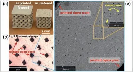
Fig.7. (a)Scaffold test specimens produced by FGF of Mg-6.3Gd feedstock.The single part on the upper left side is in the as printed green condition;the right side part is the corresponding part in the as sintered condition. The shrinkage of the as sintered part in comparison to the corresponding green part can visualized very well. (b). Light microscopy image of ground and polished scaffold specimen in the as sintered condition showing the printed open pores. The blueish rectangle demonstrated schematically the area the right side SEM image in Fig.7c was made.(c).The two corners of the SEMimage show partly two of the printed open pores and in comparison the closed residual porosity, visible as black dots, in the as sintered microstructure.The orange rectangle shows some of the closed residual pores in higher magnification. Moreover bright secondary phases can be seen which will be discussed later in the chapter 3.3: Microstructure.
3. Results and discussion
3.1. Shrinkage and residual porosity
Table 3 displays the sintering results of as sintered Mg-6.3Gd scaffold specimens after 8 h, 16 h and 32 h of sintering time at 638 °C sintering temperature, using the linear shrinkage of the specimen height.
Generally, independent of the chosen sintering time, all specimen sets obtain sufficient shrinkage, and a closed residual porosity of the microstructure as shown exemplary in the following Fig. 7c, sufficiently low for later compression test investigations. However, maximum densification through sintering,close to the theoretical maximum can be observed after 32 h sintering time obtaining a maximum shrinkage of 20.2%,minimum closed residual porosity of the densified microstructure of 2.4%, as well as open porosity of the scaffold strut structure of 40.6%. Generally, short sintering times are preferred due to economic reasons. Therefore, no longer times than 32 h were investigated.

Fig.8. left side photo image(green background)illustrates the view direction of the x-ray image (middle) and the backlighting photo image (right side) of the scaffold. It can be seen that both techniques (x-ray and backlight photo)can prof the interconnectivity of the printed and as sintered pore morphology.
Fig. 7a visualizes exemplarily the shrinkage of a sintered scaffold specimen on the right hand side in relation to its corresponding green part on the left hand side of Fig. 7a. For comparison,the x-ray images in Fig.3c(middle and left side)can as well be used to visualize the shrinkage between green part and sintered part.
The ground and polished inner structure of the as sintered scaffold can be seen in the light microscopy image in Fig. 7b. Especially the printed open pores, marked by red arrows, can still be seen after performing the sintering procedure. According to additional diagonal x-ray imaging and backlighting photo imaging of as sintered scaffolds shown in Fig. 8 as well as Archimedes density measurements, the printed pores morphology in the as sintered state is still interconnected, visible at bright shining diagonal channels in the scaffold (see yellow arrows) whereas the typical residing porosity in the as sintered microstructure remained closed as shown in Fig. 7c (see magnified area at upper right corner and yellow arrows). The closeness of the residing porosity in the microstructure is an important requirement for the later successful biodegradation and cell adhesion performance of the material [38]. Archimedes density measurements and geometrical data calculations according to Table 3 confirm that residing sintering porosity remained closed in the microstructure(Archimedes method)and printed porosity remained open and interconnected,confirmed by geometrical data assessment of the specimen and visible in Fig. 7b and c.
Generally, the remaining resin in the solvent debound green part could be completely removed applying the thermal debinding step as displayed in Fig. 5b using alternating pressure between 10 and 30 mbar at 0.4 mL of argon gas flow. Additional DTA-analysis reveals fully thermal desorption of the PPcoPE backbone copolymer at the chosen temperature/pressure profile as shown in the diagram in Fig. 9.

Fig. 9. Differenz-Thermo-Analysis (DTA) curve showing for 100% thermal decomposition of 2 mg PPcoPE backbone coploymer. The red curve displays the heating curve starting at 2 mg onto the ordinate. The blue curve displays the cooling step ending slightly below 0.0 mg due to thermal-measurement effects.
The red heating curve, starting with 2 mg specimen weight on the axis of ordinates pointed out early beginning of thermal desorption of the copolymer at 331 °C and final desorption at 397 °C. The chosen thermal debinding interval up to 540 °C seems to be too long for the copolymer. However,real printed parts of several gramms in mass and several millimeter in thickness require very low heating rate and a higher temperature range to avoid gas bubble formation inside of the parts morphology during thermal debinding due to too fast polymer decomposition. Hence, the higher the mass of the backbone polymer to be decomposed and the bigger the specimen dimensions, the longer, hotter, respectively slower the thermal debinding process has to be chosen. The blue cooling curve could move slightly below 0.0 mg due to thermalmeasurement effects.
3.2. Compression testing
The compression test results of as sintered Mg-6.3Gd scaffold specimens are exemplarily shown in Fig. 10 and in the images extracted from video capture of the compression test shown in Fig. 11.
Fig. 10 points out that in spite of minor differences in the shrinkage and residual porosities between the specimens,as shown in Table 3, no significant differences in the scaffolds compression behavior can be observed between using the short sintering time of 8 h and the long sintering time of 32 h. Applying the medium sintering time of 16 h tends to yield similar results.
The compression test of the scaffold shown in the left image in Fig. 10 was video recorded. The images in Fig. 11a to 11f originate from this video and display the scaffold condition at positions A –F in the left image of Fig. 10.
The diagrams clearly reveal that the scaffolds achieve a maximum compressive strength a little below 51 MPa (position B) applying Eq. (4) for the calculation of the scaffolds cross section area.Nevertheless,before reaching the first peak at position B the stress-strain curve comprises at least two stages similar to the typical S-shape curve of twinning in textured materials [44,45]. However, the sintering heat treatment of the binary Mg-6.3Gd alloy little above solidus and close to liquidus temperature and the slow cooling rate of the specimens afterwards corresponds to a stress-relief annealing resulting in an isotropic microstructure almost free of residual stress and texture. The first stage occurs up to position A and can only be seen in the left side curve at 8 h sintering time This stage corresponds to mechanical settlement depression due to not fully parallelism of the specimens base plates at low forces at the beginning of the test. To avoid this settlement depressing effect,the authors decided to add the top and bottom plate to the scaffolds base as described in chapter 2.2.At optimal parallelism and connection of the specimens base plates to the scaffolds strut structure,the as shown effect shall not occur as shown in Fig. 10, right side. The second stage shows curve flattening at around 25 to 30 MPa which can be explained by increased plastic deformation due to basal slip and twinning at once exhaustion of elasticity. After reaching maximal elastic and plastic deformation in the material,a cascade of struts in the scaffold structure collapses and the load decreases down to a first minimum between 40 MPa and 45 MPa (position C).
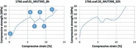
Fig. 10. Compression test results of the Mg-6.3Gd scaffold materials, sintered at 638 °C for 8 h (left side) and 32 h (right side). The points A-F refer to the photographic images in Fig. 9.

Fig. 11. (a) Start_0.0 MPa. (b). 1. peak at 51 MPa (6.7 kN). (c). 1.drop down to 41 MPa (5.4 kN). (d): 2. Peak at 48 MPa (6.3 kN). (e). 2. drop down to 44 MPa (5.7 kN). (f). End_at 61 MPa (8.0 kN).
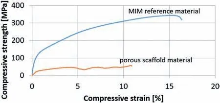
Fig. 12. Compression test result of the Mg-6.3Gd MIM reference materials,sintered at 638 °C for 64 h. For comparison, the result of scaffold material is also displayed.
Following up by a second increase of compressive strength up to 48 MPa (position D) and a second collapse of struts(position E). Finally, the compression tests were stopped after the nearly full compression and the collapse of all strut structures (position F). The batch-wise collapse of strut rows,as shown in Fig. 10 was investigated by Marvi et al. [39].However, the collapse of struts row by row beginning with the top row, followed by the bottom row as investigated in[39] cannot clearly be seen in the images in Fig. 11a-f. The deformation behavior of the binary Mg-6.3Gd scaffolds during compressing testing seems to be more uniform than the WE43-scaffolds investigated in [39]. Nevertheless, the cascade like collapse of struts took place comparable to [39] as displayed in Fig. 10.
Fig. 12 illustrates the results of a MIM reference compression test (blue curve) and a scaffold compression test (orange curve). The MIM-reference material (n= 3) as described in chapter 2.7 showed an ultimate compressive strength (UCS)of 338±7.1 MPa at 15.1±1.4%compression strain at break and 105±3.6 MPa Yield strength(YS).In comparison,an as fabricated direct chill cast material could achieve an UCS of 230 MPa [46]. The lower UCS of the as cast material can be explained due to its quite higher average grain size of 590 μm in comparison to 21 μm of the sintered MIM-material. It can be seen that the chosen binary Mg-6.3Gd MIM reference material obtained sufficient strength and stiffness, close to the mechanical properties,a biodegradable WE43 alloy can provide [47], and therefore, it is generally a suitable candidate for biomedical implant application [46,48]. The expected decrease in strength and stiffness of the porous scaffold material in comparison to the compact MIM reference material can also be clearly seen. This effect, on one hand, is due to the reduced load bearing cross section compared to a fully filled cube. On the other hand, the scaffolds strut structure implicate stress concentrations due to a notch effect. As mentioned before, Eq. (4) was used for calculation of the scaffolds cross section area, the full specimen cross section,respectively. Applying Eq. (5), which is just the cross section area of the strut-structure material, does not result in a compressive strength-level and Young´s modulus comparable to the compact MIM-reference material. The Young´s modulus of the reference bulk material was 36.1 ± 2.3 GPa. Whereas the Young´s modulus of the scaffold material,applying Eq.(5),was 7.8±3.3 GPa.Additionally,around 100 MPa UTC could be calculated using Eq.(5).Hence,the load bearing cross section of the scaffolds material cannot achieve the compressive strength of the compact MIM-reference material due to notch effect. Thus, further optimization of the strut structure geometry shall be performed in the future studies.
3.3. Microstructure
The microstructure of the FGF manufactured Mg-6.3Gd materials, independent of sintered for 8 h, 16 h or 32 h, look similar despite of minor porosity differences, as shown in Table 3. Hence, the microstructure of the FGF-material, sintered for 16 h is shown exemplary in the following Fig. 13.For comparison, the MIM reference material sintered for an identical time of 16 h is shown in Fig. 14.

Fig. 13. SEM-image of FGF Mg-6.3Gd material, sintered for 16 h at 638°C.
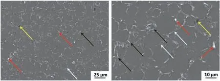
Fig. 14. SEM-image of MIM Mg-6.3Gd material, sintered for 16 h at 638°C.
Comparing the microstructure of the Mg-6.3Gd material processed by different shaping techniques reveals that both the FGF material and the MIM material achieved sufficient sintering performance and thereby low residual porosities.The observed microstructures are homogeneous and can be found all over the complete part.Typically for binder based sintering parts, some closed residual pores can be seen. The yellow arrows mark some of these roundish residing pores, which are significantly smaller than the average particle size of the used powder (d50= 39 μm) and the average grain size of the microstructure. Large defects like slag encapsulations as known from PBF-L technique cannot be observed using the binder based sintering technique FGF or MIM as well. Bright secondary phases of different types (see black, white and red arrows) can be observed at the former particle interfaces, too.
Typically, for MgGd-alloys with Gd concentrations above 2 wt%, secondary Mg5Gd-phases that occur mainly at grain boundaries can be observed, too [48,49]. These secondary phases are responsible for the good strength and stiffness values in comparison to pure Mg [50]. They did not result in embrittlement of the material as indicated by the high elongation at fracture as shown in Fig. 12. Additional EDX-spot,EDX-line and EDX- mapping analysis could confirm the attendance of Gd-rich secondary phases in the as sintered microstructure of the FGF-material as shown in the following Fig. 15. Generally three different types of bright phases can be seen: White arrows marked roundish shaped phases at former powder particle boundaries (1) containing oxygen and Gd. Black arrows mark needle shape phases (2) and red arrows mark dot-like phases (3). The roundish shaped phases(1) arise from the powder production by gas atomization using Ar and a small amount of oxygen to inert the powder and prevent it from self-igniting at air contact. The role of the oxide layer is discussed in former investigations [13,14,16]. In case of the binary Mg-6.3Gd-alloy this layer (1) contains also about 12.2 wt% ±6.8 (n= 4) of Gd which may be bound as Gd2O3. Gd-oxide cannot be solved in the matrix, even at applying solid solution heat treatment as shown in [51] using a likewise alloy and identical techniques. Spot-EDX analysis of the Mg-matrix outlines a Gd concentration of 5.3 wt%±2.2 (at number of measurement pointn= 9). This result reveals that approximately 80% of the Gd-alloying element was dissolved in the Mg-matrix.

Fig. 15. SEM-image and EDX-analysis of sintered FGF Mg-6.3Gd alloy.

Fig. 16. MgGd phase diagram [52] The redish path illustrates the phase formation at low cooling rate after finishing the sintering. The green path illustrates the solid solution heat treatment after fast quenching.
Needle shape phases (2) obtain approx. 20 wt% Gd and the bright dot-like phases even 46.7 wt%, 13.6 at% ±4.8,respectively. However, the Gd-content measurement by EDX does not point out a true value due to different phase volume and different excitation volume in dependence of the electron beam intensity, respectively. Nevertheless, the amount of 13.6 at% ± 4.8 of Gd in the bright dot-like phases (1) indicates that the phase might consist mainly from intermetallic phase Mg5Gd.The occurrence of the intermetallic Mg5Gd phase can be explained by help of the MgGd phase diagram as shown in Fig. 16 [52]. The diagram points out an atomic Gd-content of around 17% (see blue arrow) close to the measured value of 13.6 at% ± 4.8. The EDX-mapping and EDX-line scan analysis in Fig. 15 visualizes the Gd-distribution, as well as that of oxygen, carbon and silicon. The grinding and polishing preparation of the specimens involves the usage of SiC and SiO2. Therefore, it cannot be clarified within this study if Si, C and O originate from the applied material (Si, oxidelayers), from the processing (oxidation, C-binder residuals) or from the preparation (SiC, SiO2). This question can be answered only by performing a complex crosscheck experiment and analysis setup using additional binder free processing in combination with additional Si-, O- and C-free grinding and polishing agents as there are TiC or BN. However, the line scan clearly illustrates that Gd did not occur significantly in any bright phase. Especially the former particle layer surface(1) seems to consist mainly from magnesium oxide and only marginally from Gd or gadolinium oxide.
The red illustrated path 1 in the diagram points out the phase formation after finishing the sintering step. The specimens can only cool down slowly according the cooling performance of the sintering-furnace. Hence, a Gd-rich liquid phase can occur upon reaching the liquidus and an enrichment of the Gd-concentration in the Mg-alloy up to eutectic concentration of 38.4 wt% Gd at 548 °C takes place. At a temperature lower than eutectic temperature of 548°C,the Gd was mainly consumed to form the intermetallic phase Mg5Gd.In comparison, the green illustrated path 2 demonstrates the solid solution heat treatment after quenching the specimens from the solidus temperature between 510 °C and 540 °C,resulting in the super saturation ofα-Mg-matrix by Gd.
In view of later usage as biodegradable material, huge amounts of these Mg5Gd intermetallic phases can effect micro galvanic corrosion behavior and rapid degradation. Hence additional solid solution heat treatment followed by precipitation hardening can be an issue for later optimized processing in view of the final biomedical usage [46]. Nevertheless, solid solution heat treatment and precipitation hardening of binary MgGd alloy did not result in significantly higher strength,stiffness or compressibility[48,50].Hence,solid solution heat treatment was not involved in the framework of this study.
3.4. Simulation modeling

Fig. 17. Stress-strain curve of the scaffolds tested experimental in compression (blueish curves) and simulated in compression (orange curve).
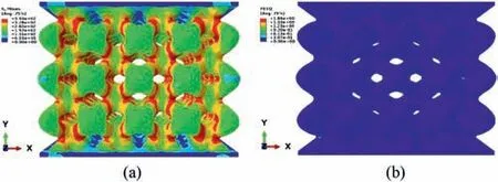
Fig. 18. (a) Mises stress field of the deformed scaffold in 10% compression strain. (b) equivalent plastic strain field of the deformed scaffold in 10%compression strain.
Measured engineering stress-strain curves of the scaffolds,tested in compression, are plotted in Fig. 17 up to 10% strain,together with the numerical prediction. It is demonstrated that the finite element simulation is able to predict the initial linear elastic as well as the onset of plastic instability,with acceptable accuracy. The excellent agreement, at least up to 5% strain, confirms the ability of the printing set up to fabricate all complexities in the scaffold geometry following the STL file. Moreover, since no microstructural defect (e.g.voids, cracks) is implemented in the FE model, the agreement reveals that the role of microstructural defects on the compression properties of the printed scaffold is negligible.The Mises stress field of the deformed scaffold in 10% compression strain, see Fig. 18a, shows the stress localization near the intersection of struts. At this stage of deformation,one could barely observe the trace of plastic deformation of the bulk material (Mg-6.3Gd), see equivalent plastic strain field in Fig. 18b. It is noteworthy that the current calculated stress-strain curve does not capture the drop in the load after 5% strain. This indicates the necessity of implementation of damage and fracture in the simulation. The crack formation triggered by high stress concentration at the intersection of struts, leads to progressive collapse of cell layers in the scaffold [39]. In the absence of fracture in the modeling strategy and energy release due to the formation of cracks, closeness of the cells during compression advances the densification of material. The latter explains the continuous increase in load observed in the numerical calculations shown in Fig. 17 after 5% strain. FE analysis up to higher strains together with compression test results assisted by Digital Image Correlation needs to be carried out to assess the deformation/failure mechanism of the Mg-6.3Gd scaffolds.
4. Conclusions and outlook
This study points out the general suitability of using binder based 3D printing technology, in detail Fused Granular Fabrication (FGF), for the successful manufacturing of complex shaped tiny scaffold parts made of Mg-6.3Gd alloy for biomedical application The scaffolds printed and sintered achieve good strength and stiffness obtaining above 40%of open porosity and good reproducibility. The MIM produced compact reference material could achieve compressive strength of 338±7.1 MPa at 15.1±1.4%compression strain at break. Moreover, DSC-analysis of the thermal debinding step demonstrates successful thermal decomposition of the backbone polymer. However, a crosscheck experimental setup of binder free material vs. binder containing material in combination with analysis of the carbon content will proof that fully residual free thermal debinding can be performed successfully. Such crosscheck experiments in combination with XRD-measurements, using silicon-, carbon- und oxygen-free grinding and polishing agents,shall also be performed regarding the question where silicon, oxygen and carbon, detected by EDX were coming from.
As mentioned in the introduction chapter, Gd as an alloying element is beneficial for both the increase in mechanical properties with low degradation rates and good biocompatibility in Mg materials [53]. In view of these observations, the properties of the scaffold structures fabricated in the present study should allow for bone repairs and cell ingrowth while maintaining low degradation rates. These properties, however,will be the subject of future investigations.
Furthermore, a finite element-based simulation strategy was employed to model the mechanical properties of FGFprinted Mg-6.3Gd biodegradable scaffolds. The finite element model was built up using the STL file, which was used to manufacture the scaffold. The Mg-6.3Gd material was assumed to behave as an isotropic, elastic-plastic solid following the J2 theory of the plasticity. The initial linear elastic as well as the onset of plastic instability were reproduced accurately. Simulation results showed the early localization of stress at the intersection of struts as well as lack of plastic deformation of Mg-6.3Gd material up to 10% of strain.Since the study of mechanical properties of scaffold up to very high strains through numerical simulation was out of the scope of the current work, further modeling investigation on deformation and fracture mechanism is postponed for the second issue. Fracture in the form of ductile failure model will be introduced to the model. Comprehensive validation of the model will be conducted through assessment of numerical results against stress-strain curve, stress/strain fields captured by Digital Image Correlation and recorded 3D deformation mechanism via in-situ micro X-ray Computed Tomography(XCT) of the scaffold under progressive compressive loading.In addition, mass diffusion analysis coupled with mechanical analysis is performed to take into account the mass-loss of the scaffold in the simulated body fluid environment and the consequent degradation of the mechanical behavior of the scaffold. However, these are the very first promising results of comparing experiments and simulation of compression behavior of binder based 3D-printed Mg-alloy scaffolds. The authors decided to use these MIM-compressive test data for the numerical modeling because it can be assumed that they show basically the same performance from sintering. The excellent agreement of simulation results with the experiment for the scaffold verifies the correctness of this hypothesis.Next steps of development are refinement of the printed structure in the direction of smaller strut geometries and pore sizes below 500 μm in diameter,investigation of solid solution-and precipitation hardening heat treatment which may be necessary for the further biomedical approach and involvement of the biodegradation performance of the printed and sintered scaffold using real experimental approaches and comparing simulations.
Author contributions
Martin Wolff conceived and designed the experiments;Mohammad Marvi conceived and designed the simulation strategy and modeling software, Henrik Lueneburg, Eshwara Nidadavolu, and Martin Wolff performed the experiments and analyzed the data;the Helmholtz-Zentrum Hereon contributed materials and analysis tools;Martin Wolff,Mohammad Marvi,Thomas Ebel and Regine Willumeit-Roemer wrote the paper.
Declaration of competing interest
The founding sponsors had no role in the design of the study; in the collection, analyses, or interpretation of data; in the writing of the manuscript, and in the decision to publish the results.
Acknowledgment
The Authors thank the Alexander von Humboldt Foundation for the award of the Post-Doctoral Fellowship to M. Marvi-Mashhadi to undertake this research work. Eshwara Nidadavolu acknowledges the support from the Bundesministerium für Bildung und Forschung (BMBF) through BioMag3D project code Nr. 03VP09852 to undertake this research. The contribution of the “Institute of Material Systems Modeling” at HEREON, directed by Prof. Christian Cyron,to provide computational resources is highly acknowledged.Moreover, we would like to thank Dr. Domonkos Tolnai, Dr.Hajo Dieringa, Dr. Dietmar Letzig and Dr. Jan Bohlen for their helpful support.
杂志排行

Journal of Magnesium and Alloys的其它文章
- Characterizations on the instantaneously formed Ni-containing intermetallics in magnesium alloys
- Corrosion resistance of Mg-Al-LDH steam coating on AZ80 Mg alloy:Effects of citric acid pretreatment and intermetallic compounds
- Gradient structure induced simultaneous enhancement of strength and ductility in AZ31 Mg alloy with twin-twin interactions
- In-depth analysis of the influence of bio-silica filler (Didymosphenia geminata frustules) on the properties of Mg matrix composites
- Effect of Cd on matrix structure ordering and aging precipitation evolution in a Mg-Gd-Cd solid-solution alloy
- A multifunctional osteogenic system of ultrasonically spray deposited bone-active coatings on plasma-activated magnesium