Magnesium-based nanocomposites: A review from mechanical, creep and fatigue properties
2023-11-18AzriShmsipurBkhshshiDrlihGolmnShriIsmilRzzghi
S. Azri, A. Shmsipur,∗, H.R. Bkhshshi-R, J.W. Drlih, J. Golmn, S. Shri,A.F. Ismil, M. Rzzghi
a
Department of Materials and Metallurgical Engineering, Amirkabir University of Technology, Tehran, Iran
b Advanced Materials Research Center, Department of Materials Engineering, Najafabad Branch, Islamic Azad University, Najafabad, Iran
c Department of Materials Science and Engineering, Michigan Technological University, Houghton, MI 49931, USA
d Department of Biomedical Engineering, Michigan Technological University, Houghton, MI 49931, USA
e Advanced Manufacturing Research Group, Faculty of Mechanical Engineering, Universiti Teknologi Malaysia, Johor Bahru 81310, Johor, Malaysia
fAdvanced Membrane Technology Research Center (AMTEC), Universiti Teknologi Malaysia, Johor Bahru 81310, Johor, Malaysia
Received 5 April 2023; received in revised form 28 July 2023; accepted 13 August 2023
Available online 12 September 2023
Abstract The addition of nanoscale additions to magnesium (Mg) based alloys can boost mechanical characteristics without noticeably decreasing ductility. Since Mg is the lightest structural material, the Mg-based nanocomposites (NCs) with improved mechanical properties are appealing materials for lightweight structural applications. In contrast to conventional Mg-based composites, the incorporation of nano-sized reinforcing particles noticeably boosts the strength of Mg-based nanocomposites without significantly reducing the formability.The present article reviews Mg-based metal matrix nanocomposites (MMNCs) with metallic and ceramic additions, fabricated via both solid-based (sintering and powder metallurgy)and liquid-based(disintegrated melt deposition)technologies.It also reviews strengthening models and mechanisms that have been proposed to explain the improved mechanical characteristics of Mg-based alloys and nanocomposites.Further,synergistic strengthening mechanisms in Mg matrix nanocomposites and the dominant equations for quantitatively predicting mechanical properties are provided.Furthermore,this study offers an overview of the creep and fatigue behavior of Mg-based alloys and nanocomposites using both traditional (uniaxial) and depth-sensing indentation techniques. The potential applications of magnesium-based alloys and nanocomposites are also surveyed.
Keywords: Magnesium-based nanocomposites; Nanoreinforcement; Strengthening mechanisms; Creep properties; Fatigue properties.
1. Introduction
Magnesium (Mg) is significantly lighter than other structural materials due to its density of 1.73 g/cm3, making it approximately 77%, 61%, and 33% lighter than stainless steel,titanium, and aluminum, respectively. As a result, Mg-based alloys are promising candidates for replacing the aforementioned structural metals [1,2]. Additionally, magnesium is the fourth most abundant element on the planet after iron, oxygen, and silicon [3]. Mg is a key lightweight material that has seen widespread use in ambient temperature applications over the past decades [4]. Mg-based alloys are less prone to H2porosity and their melts are very fluid, making them more castable than other metals such as aluminum and copper [5].For example, Mg can be die-cast at a 50% higher rate than aluminum [6]. Electromagnetic shielding and versatility are two other unique properties of Mg [7–9]. Magnesium absorbs the impact energy making it excellent structural material for damping and load-bearing applications [9]. The comparative ease of machining Mg-based alloys makes it more feasible to fabricate complex designs with high dimensional accuracy[10]. This is an important consideration for uses in medical [11–13]. Furthermore, the thermal conductivity of Mg is much greater than polymers. Yet, unlike polymers, Mg can be recycled completely [14–17]. Using Mg-based materials in automotive, aerospace, defense and construction applications can significantly reduce energy consumption.Two key properties of these emerging materials are high specific strength and adequate ductility [15–18]. Mg alloys are classified according to their significant alloying elements. Aluminum, zinc, rare earth elements, thorium and zirconium are a few of the main elements that are used for alloying Mg-based alloys depending on the application [3,19–21]. Mg-based materials are an excellent choice to use in weight-critical applications due to their great specific strength. Mg-based materials also have a high creep life and good dimensional stability [22,23]. However, a major limitation is the high and uncontrolled corrosion rate of Mg-based alloys.The corrosion resistance and material properties of Mg-based alloys could be improved by incorporating different alloying elements. There is always a trade-off when alloying to improve corrosion resistance, which must be carefully tailored to the specific application [24,25]. Pure Mg oxidizes rapidly in air and its powder is naturally pyrophoric [26]. Pure Mg was oxidized for different times and temperatures in 20 kPa O2. The disadvantage of Mg is its strong reactivity, which limits its corrosion characteristics in many aggressive solution. MgO is not stable in aqueous solutions[12]. Fournier et al. [12] measured the thickness of the oxide coating generated during 15 min of oxidation at room temperature.At ∼300°C,the oxide develops according to the inverse logarithmic growth law. The oxide layers generated at∼300 °C in dry oxygen are similarly exceedingly thin, owing to a low defect density. Mg evaporation occurs during oxidation at ∼400 °C, and MgO nodules are produced on the surface. The as-cast monolithic Mg has a mechanical strength as low as about 20 MPa and a high corrosion rate, resulting in hydrogen gas release [16]. Another drawback of Mg-based alloys is their poor RT toughness, because of their HCP crystalline structure that limits activated independent slip systems[27].

Fig. 1. (a) 0.2% YS and (b) 0.2% CYS of some MMNCs. In different reinforcements based on the concentration, the strengths vary in a range between low and high values [27].
One promising route to address the drawbacks of Mg-based alloys is to develop Mg-based nanocomposites (NCs) with nano-sized reinforcements.The fabricated NCs display a combination of increased mechanical characteristics and improved corrosion behavior as well as an acceptable performance at high temperatures. Nano-sized reinforced metal-matrix composites (MMCs) are emerging recently because of their excellent characteristics that make them a potential option for many different applications. Due to the small size of the reinforcements, the interaction of reinforcement particles with dislocations in nano-sized reinforced metal matrix composites is stronger than in conventional MMCs. This can result in greater improvement of mechanical properties in Mg-based metal matrix nanocomposites (MMNCs) compared to conventional MMCs[28,29].Magnesium MMCs can be prepared using a variety of particulate reinforcements, such as metals (Ti,Mo, Cu, Ni), carbides (SiC, ZrC, TiC, B4C), oxides (Al2O3,TiO2.MgO, Y2O3, ZnO), borides (ZrB2, TiB2, SiB6), and nitrides (BN, AlN, TiN, ZrN) [27–30]. Fig. 1 depicts the 0.2%yield strength (YS) and tensile (UTS) and 0.2% compressive strength of Mg-based NCs reinforced with various nanoparticles(NPs)and monolithic Mg[27].As can be seen in Fig.1a,Al,Y2O3,and NiTi can remarkably enhance the TYS of magnesium. Also, Fig. 1b shows that ZnO and Sm2O3particles can remarkably enhance the CYS of magnesium. The concentration of reinforcement can change the mechanical properties of NC [27]. The nano-Sm2O3additions contribute to the strengthening of the Mg base using pinning grain boundaries and inhibiting dislocation motion. These become more prominent as the particle volume content increases (closerspaced impediments to dislocation motion).Energetically,this makes dislocation glide and cross slide more difficult, leading to enhanced work hardening performance and creep resistance. Furthermore, increasing the loading rate from 0.05 mN/s to 5 mN/s increases the rate of dislocation development and multiplication, causing matrix work hardening and improving the interaction among existing nano-additions and dislocations [18]. Tensile and compression strength of Mg alloys are often increased with the addition of a reinforcement phase. Within a particular range, the yield strength of the Mg matrix composite enhances linearly with the increase in the amount of the reinforcement. In general, the incorporation of nano-reinforcements to the Mg-based results in increased strength of the nanocomposite product due to a variety of mechanisms such as the efficient load transfer, work hardening, Hall-Petch effect, and Orowan looping caused by dislocation and strain mismatch between the nanoadditives and the matrix. The Hall-Petch formula states that the finer the grain size, the greater the YS of the alloy. When Mg alloy grains are refined to ∼1 μm, their YS may reach over 300 MPa,greatly exceeding common steel Q235 and high-strength Al-Si alloys. Fine grains may boost the number of grain boundaries(GB) per unit volume, that would not just inhibit dislocation movement to enhance strength, but also restrict fracture propagation to enhance plasticity [31]. The Orowan strengthening process reinforces the composite by hardening the metal matrix.This strengthening mechanism,nevertheless,is highly dependent on the size and dispersion of the reinforcement additions. As a result, the Orowan strengthening process can only strengthen Mg composites if the reinforcement particles are sub-micrometer in size and dispersed evenly in the Mg-base[32]. The Orowan strengthening influence of organically generated precipitates in Mg alloys (including (0001) plane, (11–20) plane, (10–10) plane, and [0001] rod)) on different slip modes(including pyramidal I
It is important to note that theoretical backgrounds for infractions through the strength-ductility relationship, such as the concept of strengthening mechanisms and structural factors for altering strengthening mechanisms, are critical for acquiring a deeper understanding of strengthening and toughening mechanisms [1,2,38-47]. The dominant equations for quantitatively predicting the mechanical characteristics and underlying synergistic strengthening mechanisms in Mg-based alloys and composites are critical for addressing the aforementioned issue. These equations are affected by reinforcing material characteristics such as particle size, volume fraction,interparticle distance in the matrix, variations in thermal expansion of the particles, etc., that can affect the mechanical characteristics of the composites. However, there are still major inconsistencies regarding the governing equations for Mgbased alloy and composite strengthening mechanisms [1,2,38-47]. This review discusses the influences of nanoadditions on the mechanical characteristics, the creep and fatigue behavior and obtaining dominant equations to statistically predicted the mechanical characteristics of Mg-based materials.It also offers a comprehensive review regarding the synergistic strengthening mechanisms including grain boundary reinforcement,load transfer,solid solution,crack deflection,crack branching function, and precipitation strengthening processes of Mg-based materials for various biomedical and industrial applications.
2. Mechanical properties

Fig. 2. (a) Classification of metal matrix composites based on the morphology of reinforcing material [45], (b) Mechanical variable that can be adjusted by fabrication an optimised Mg-based composites [45], (c) Brief of the feasible impact of the solid solution of various alloying elements and their combinations on the characteristic of Mg alloys [13], and (d) Illustration of the effect of different reinforcements on 0.2% YS and ductility of Mg [2].
The mechanical characteristics of structural materials are typically associated with the microstructure,microscopic crystal structure defects, whose interactions, as demonstrated by experimental findings, numerical simulations, and theoretical models, can induce effective strengthening mechanisms. The characteristics of an MMC depend on the characteristics of its constituents including the matrix and reinforcements. In magnesium-based MMCs, the shape, content, and quality of reinforcement distribution can influence dislocation behavior,including dislocation movement through the microstructure of composite and its subsequent effect on mechanical characteristics. Immobile crystalline flaws (e.g., precipitates [48], forest dislocations [49], and GBs [50], etc.) together act as local locations impeding glissile dislocations or deformation twinning from moving. As a result, theoretical foundations for overcoming the strength-ductility trade-off paradox, such as the idea of strengthening mechanisms and structural variables for affecting strengthening mechanisms, are critical for deepening understanding of strengthening and toughening mechanisms [37,51].
Metal matrix composites (MMCs) might be categorized into (i) particle fillers, (ii) short fiber fillers, and (iii) continuous fiber fillers composites as exhibited in Fig. 2a [45]. There are many feasible variable of a metal matrix that might be different by compositing with fillers (Fig. 2b) [45]. In addition,the fillers have a substantial impact on the strength, plasticity,and other characteristics of Mg. Choosing the fillers with adequate strength and stiffness as well as superior compatibility with the matrix along with more uniform distribution within the matrix and higher matrix-filler interface integrity leads to improvement of the properties of magnesium alloys. Furthermore, the feasible outcome of the solid solution of various alloying elements and their synergetic effect on the characteristics of Mg-based composites are also outlined in Fig. 2c [13].The ultimate compressive strength of MMNCs(219 MPa)was 91% greater compared to the pure Mg, and this could be a consequence of interstitial solid solution strengthening because of the difference in atomic radius between matrix and fillers [13]. To enhance mechanical performance Zn, Zr, Sr,Ca, Nd, Ce, Y, Gd, Mn, and Al are widely used to develop Mg-based composite. Other fillers are also incorporated to fabricate Mg-based composites including, ZnO, TiO2, MgO,ZrO2,Y2O3calcium phosphate-based ceramic,bioactive glass in order to enhance mechanical properties.
Liu et al. [52] demonstrated Mg-RE alloys demonstrated a wide range of UTS (from 76 MPa to 354 MPa), YS (from 40 MPa to 316 MPa), and elongation (from 0.7% to 60%).YS and UTS increased whereas elongation diminished as the rare earth content in Mg-RE binary alloys boosted. Most Mg-RE binary alloys had YS and UTS less than 100 MPa and 200 MPa, respectively, and elongation less than 10%. Overall, the adequate strength of Mg-RE binary alloys is lower than that of WE43 alloy for usage as implant materials. Extruded WE43 had an elongation of greater over 35%. Mg-Zn-Y alloys (Mg-1.73Zn-1.54Y, WZ21, ZW21, and ZEK100)have similar yield strength and ultimate tensile strength to WE43, with only about 28% elongation. However, with elongation of 15%-25%, the YS and UTS WE43 of JDBM and Mg-2.4Zn-0.8Gd alloys surpasses those of reaching 280 MPa and 310 MPa, respectively. The YS and UTS of Mg-4Y/Ce-1Zn-1Mn alloys were around 120 and 170 MPa, respectively, lower than those of WE43. Mg-4Ce-1Zn-1Mn alloy elongation reached 60%, suggesting that the incorporation of Ce element improved elongation more than the incorporation of Y. Furthermore, heat extrusion [53] and solution treatment both enhanced the strength of Mg-RE alloys in general, whereas solution treatment reduced the strength of Mg-Dy binary alloys and Mg-2.4Zn-0.8Gd alloy. In general, the findings indicate that alloying or fabrication methods changes could be used to produce Mg-RE alloys with the acceptable range of mechanical characteristics for utilization in biodevices [52].
Many investigations have recently been performed to determine the influence of various reinforcements including Al2O3[54,55], TiO2[56], Y2O3[57], ZnO [58], ZrO2[59], carbides (SiC [60], B4C [61] and TiC [62]), nitrides (BN [63],AlN [64] and TiN [65]), borides (TiB2[66], ZrB2[67]), carbon nanotube (CNT) [68,69] and graphene [70] on mechanical characteristics of the Mg-based matrix. Based on these studies, a remarkable enhancement in yield strength could be achieved by adding the reinforcement. This enhancement in mechanical characteristics could be due to direct strengthening by the second phase and refinement of grains in the Mg-based matrix.
But the incorporation of micron-size additions reduces the ductility of the Mg-based significantly because of particle cracking and creation of voids at the interface between Mg matrix and particle, resulting in hastened failure. As a result,hybrid (Ceramic + Metallic) Mg NCs were discovered to have an optimal mix of strength and ductility, outperforming traditional Mg + Ceramic or Mg + MNC. It was reported[2,14,52,71], the encapsulation of metallic fillers improves strength but decreases ductility of composites, whereas ceramic reinforcement enhances ductility but decreases strength enhancement. The greater improvement in strength for metallic reinforcements could be attributed to improved wettability between metallic additions and Mg-base [14,71], as well as the influence of solid solution strengthening, which is omitted as ceramic additions are applied. The other study [2] regarding three Mg NC (MgTi, MgCu and MgAl) reveal that MgAl and MgCu composites have a greater increase in strength and a lower ductility than MgTi. This is because to increased solubility of Al in Mg, the creation of the Mg Cu intermetallic phase, and limited solubility of Ti in Mg [2]. Regardless of the manufacturing procedure, enhancements in the mechanical characteristics of Mg NCs were seen when compared to monolithic Mg. In fact, the increase in ductility and yield strength is dependent on the fabrication methods and additives used.
Mg and Mg-based alloys have a low ductility at RT because of their crystal structure, which is a hexagonal close pack(HCP)[6].This is due to the fact that at RT(and,in fact,at temperatures below 200 °C), the basal slip and twinning mechanisms are typically the only ones that undergo plastic deformation, and the critical resolved shear stress (CRSS) for basal slip plane’s systems is noticeably lower than that of non-basal ones (prismatic and pyramidal) [72].
The influence of the addition of various reinforcements on the ductility and 0.2% yield strength (YS) of Mg is shown in Fig. 2d [2] . Metallic reinforcements remarkably improve the strength of Mg but decrease its ductility(green bubble).As an example, 0.6 wt% Cu improves the 0.2% YS of magnesium by 104% but decreases the ductility marginally. Ceramic reinforcements generally increase ductility, but the improvement of strength by ceramic reinforcement is normally less than by metal reinforcement. The higher strength improvement from metallic reinforcement may be related to the superior wettability between metallic reinforcements and Mg-based matrix compared to ceramic reinforcement [14,70]. Additionally, the solid solution strengthening mechanism in metal-reinforced Mg is not present in ceramic reinforcement. It is reported[2] by researchers working on MMCs, strength and ductility could be improved simultaneously.
In this regard, it was depicted the mechanical properties of certain biodegradable Mg alloys samples with different circumstances [2,52,73–76]. Whereas Si, Ca, and Sr elements have proper cytocompatibility,their mechanical characteristics are unfavorable due to their reduced solubility in Mg alloys when as compared to Zn. Their second phases are frequently thick and distributed along the grain boundary, which is detrimental to the improvement of Mg alloy mechanical characteristics.Except for the alloying procedure, new methods of processing (ECAP, HPT, and CEC) must be used to improve the mechanical characteristics of Mg-Ca, Mg-Sr, and Mg-Si alloys.Mg-Zn alloys often have outstanding mechanical characteristics due to Zn has fairly high solubility in Mg (6.2 wt%)and the ability to perform dual roles in both solid solution and precipitation strengthening. Furthermore, because of the precipitation strengthening and solid solution, RE-containing Mg alloys often have strong mechanical characteristics. The combination of Zn and RE as alloying elements may be the ideal alternative for studying novel biodegradable Mg alloys with excellent mechanical characteristics. Powder metallurgy is one of the frequently used processing methods to create Mg NC [77,78], melt-stirring [79], disintegrated melt deposition (DMD) [80–82], high pressure die casting [83,84], spark plasma sintering (SPS) [52,53], etc. Table 1 evaluates the advantages and challenges of different fabrication methods of the Mg-based composite.
3. Composite strengthening mechanisms
Mechanisms of strengthening by the addition of reinforcement in MMCs can be categorized as direct and indirect strengthening. The effectiveness of the strengthening mechanisms depends on the microstructure and fabrication pro-cess of the specific composite. In NCs fabricated based on powder process, the grain size can be very small, which can affect the strength. In nanocomposites processed using melt-based methods, the grain size is large and comparable to the unreinforced matrix [14]. Direct strengthening is an extension of the conventional mechanisms of composite strengthening in particulate-reinforced composites. In this mechanism, the applied load is transferred from the matrix to the stiffer reinforcing particles via the interfaces between them, and the composite becomes stiffer due to the capacity of bearing the load by reinforcement. Based on the reports, the matrix-reinforcement interfacial bonding works effectively in transferring the applied load from the matrix to the reinforcing particles[112,113].For example,Fukuda et al.[114]fabricated CNT-reinforced AZ61 magnesium alloy using the powder metallurgy method. AZ61/0.74 vol% CNT composite displayed ∼340 MPa excellent tensile strength and∼11% acceptable elongation. Based on their results, the formed Al2MgC2ternary carbide in the structure dispersed discontinuously at the structural defects of CNTs without causing damage to CNTs, thereby reinforcing the interfacial bonding strength between the AZ61 matrix and CNTs and improving the composite strength.

Table 1 Comparison of different metallurgical techniques for making Mg-based nanocomposites.

Table 1 (continued)

Table 1 (continued)
However, it should be recognized that the addition of reinforcement in excessive amounts reduces the composite’s mechanical properties due to the weakening of bonding strength between reinforcement particles and matrix that leads to stress concentration. For example, Khalajabadi et al. [115] fabricated hydroxyapatite (HAp) and TiO2-reinforced magnesium NCs (Mg-x1HA-x2TiO2) using different contents of reinforcements (x1= 27.5, 20, 12.5, and 5 wt% /x2= 0, 5, 10, and 15 wt%). They fabricated the NCs via a powder metallurgy process including mechanical milling, compacting, and sintering. Their outcomes revealed that high concentrations of HAp result in clustering and high porosity, and a subsequent decline in the compressive failure strain of the NC. Based on the circumstances, it can be concluded that the strength of particle-reinforced composites is most strongly influenced by the reinforcement volume fraction and only slightly less by particle size. Additional strength can be added to the composite through normal matrix strengthening caused by solution and precipitation hardening [116]. In indirect strengthening,the reinforcement can improve the mechanical characteristics of the composite by changing the microstructure of the matrix. This occurs when the composite develops dislocations due to strain from either an external load or a difference in the coefficient of thermal expansion (CTE) between the matrix and the reinforcing particles. Grain size refinement and Orowan strengthening by the reinforcement are also indirect strengthening mechanisms. Ceramic reinforcements can refine the grains, activate the non-basal slip systems, modify the texture of magnesium, and improve the ductility of the resulting NC [32]. Regardless of indirect strengthening mechanism, the improvement strongly depends on the dispersion of nanosized particles and their content in the NC. The (0001)˂1120˃basal slip is the most readily activated of Mg’s deformation system at ambient temperature [117]. In hot-extruded Mg, a strong fiber texture is developed that aligns the basal plane parallel to the extrusion direction (ED) [118]. As a result, during compression and tensile loading, the basal slip is prevented in the ED. Due to the inhibition of basal slip activation, Mg deformation could occur from twinning. For example, Garcés et al. [119] showed that the twinning system(10¯12)[10¯10] is inactive in tension and only active in compression as twinning generates an extension perpendicular to the ED and parallel to [0001]. Non-basal dislocations are developed and moved due to the applied tensile load and the alignment of the slip planes after extrusion. A much higher ductility can be achieved in magnesium by activating nonbasal cross slip, which enables a minimum of 5 different slip systems (3 from basal and 2 from non-basal slip systems).
Overall, the incorporation of micron-size additions reduces the ductility of the Mg matrix significantly because of particle cracking and the development of voids at the particlematrix interface, resulting in accelerated failure. According to a result, hybrid (Ceramic + Metallic) Mg NCs were discovered to have an optimal combination of strength and ductility, exceeding traditional Mg + Ceramic or Mg + Metallic NCs [1,2]. The two primary forms of twin geometry in Mg alloys are "cross structure" and "parallel structure." Twins will develop immediately after nucleation in a "parallel structure" (as depicted in Fig. 3i(a)) and continue to expand until they reach the grain boundary (GB). Twins can also be made thicker to enable more plastic deformation [120]. A "cross structure"(a twin-twin interaction) occurs when several twin types are activated simultaneously and have an effect on one another[120,121].Twin variations oriented in opposing directions nucleate and grow quickly until they come into touch with one another to form the "cross structure" (as depicted in Fig. 3i(b)) [120]. The dislocations at the incident twin’s tip interact with the TB dislocations, causing stress concentration due to dislocation accumulation that affects the twins’future development [120]. According to several research, the twin interaction has a major effect on the twin propagation,de-twinning, and twinning-induced strain hardening effects of Mg alloys [120,121].
Fig. 3ii depicts a grain twinning process schematically[122]. From left to right, Fig. 3ii (a) depicts the twinning process, which includes twin nucleation, propagation, and development. It indicates that under some conditions, a twin is nucleated at a grain boundary. The newly produced twin then propagates in the twin shearing direction on the twinning plane when it gets to the opposite side of the grain boundary,producing a twin band. At the end of the propagation stage,this twin band crosses the grain. It is believed that the thickness of the twin band does not greatly expand during rapid propagation, and hence the volume ratio of twin is comparatively small. Twin expansion, or thickening of the twin band,characterizes the final step of the twinning process. As previously stated, there is a tension reduction soon following twin nucleation and during the propagation stage [122]. The stress relaxation process is depicted schematically in Fig. 3ii (b) in terms of the twinning resistanceTαas a function of the twin volume fraction. The resolved shear stress must overcome a great resistanceTα0from nucleation. The resistance to twinning diminishes during twin propagation to its minimumTαgat the twin volume fractionfα=fαg. According to Fig. 3ii,the stress relaxation correlated to twin nucleation causes the twin to propagate spontaneously and develop a twin band,whereas the material in the twin drives the twin thickening.It’s essential to highlight that this work-hardening is not always a result of twinning. It may result from the slip of the materials in the twin as the extension twin in wrought Mg alloys re-orients the material inside the twin to a hard orientation [122].

Fig. 3. (i) schematic maps of the two forms of twin-twin growing behavior processes, (a) Parallel structure, (b) cross structure [120], and (ii) schematic depictions of (a) twin nucleation, propagation, and growth in a grain and (b) resistance to twin nucleation, propagation, and growth [122].
Further, Sankaranarayanan et al. [58] developed Mg NCs with different ZnO reinforcement contents (0, 0.16, 0.48, and 0.8 vol.%). Analysis of texture utilizing XRD and EBSD investigations revealed that the weakening of the basal fiber texture in ZnO-reinforced Mg-based NCs helps to facilitate slip transition by activating the non-basal cross-slips. This helps to decrease tension-compression yield asymmetry and increase tensile ductility. Additionally, intending to investigate the influence of the CNT reinforcement addition to Mg,Goh et al. [123] fabricated Mg-1.3CNT NC and compared its properties to pure Mg. They demonstrated that the activation of cross-slip and non-basal slip during tensile deformation is aided by the presence of CNTs in NC. Fig. 4(i,ii) show the structure of dislocations using TEM after tensile fracture in pure Mg and the 1.3 wt% CNTs reinforced magnesium NC, respectively [123]. For pure magnesium, small numbers of basal dislocations lie parallel to the basal plane trace as shown in Fig. 4(i-a), and no ˂c+a˃dislocation is seen.As exhibited in Fig. 4(i-b), which depicts extensive non-basal dislocations with a component Burgers vector, the non-basal slip systems are significantly more active compare to the basal slip systems. Following tensile deformation, cross-slipping of the basal in the Mg-1.3CNT NC is depicted in Fig. 4(ii-a,b).The(10¯10), (0002) and(10¯11)pole figures of Mg-1.3CNT nanocomposite after extrusion was observed in the figure.The texture of monolithic Mg is similar, with the c-axis roughly perpendicular to ND. Their result also exhibited that mainly pyramidal ˂c+a˃dislocations traverse between the basal and non-basal slip planes. Texture investigations using XRD pole figures for Mg-1.3CNT NCs showed that the prismatic,pyramidal, and basal planes are not precisely aligned along the specimens’ extrusion direction at 90°, 0°, and 45°, respectively. The activation of non-basal slip is favored by the 3 planes being tilted at random around 20° of their respective ED as shown in Fig. 4 (iii-a,b) [123].
3.1. Strengthening and deformation mechanisms of additive reinforced MMNCs
In summary, there are recognized various synergistic strengthening systems for the Mg matrix. These mechanisms are load transfer, solid solution strengthening, grain refinement, work hardening strengthening, and Orowan strengthening mechanisms, and they are discussed in subsequent subsections. Many studies have tried to predict the mechanical characteristics of NCs by proposing equations based on these different strengthening mechanisms[124].The proposed equations have various parameters of reinforcements that influence the mechanical characteristics of NCs including size,content, particle distance in the matrix, and the difference in particles’ CTEs. However, the governing equations differ significantly from one literature to the next. The governing equations proposed in the existing research are summarized in Table 2, but they are not discussed in detail in this review. Fig. 5 depicts a schematic of the deformation mechanisms in Mg-Al-Ca (AX61) alloy [40]. Basal slip was initially initiated in Mg after yielding. Geometrically necessary dislocations (GNDs) are produced via dislocation pile-up at the Al2Ca/Mg contacts. Following dislocation slip or stacking faults on the {111} plane, Al2Ca deformed. Ca segregation causes non-basal dislocations to form at grain boundaries[40].The significant work hardening as well as high tensile elongation of this material are caused by the nonshearable yet malleable Al2Ca and the increased
3.2. Thermal expansion strengthening
In ceramic-reinforced MMCs, the difference between the high CTE metallic base and the low CTE ceramic reinforcement is significant. During the cooling time after sintering,this thermal mismatch causes dislocations to form at the interface between the matrix and reinforcement. Work hardening of the matrix is induced by a mismatch in CTEs between the matrix and addition, which is primarily due to prismatic punching of dislocations at the interface reinforcement and matrix [136,137]. The greater interfacial bonding YS of MMNCs during plastic deformation is stimulated by the CTE difference between the metal matrix and reinforcement phase[138]. Mechanical strengthening in graphene nanoplatelets(GNP)-reinforced magnesium composite, due to the DTEs was reported by Rashad et al. [139,140]. Also, Habibnejad-Korayem et al. [141] showed how the addition of nanoscale Al2O3particles caused a DTE strengthening mechanism,leading to improvements in the mechanical characteristics of the Mg-based. These studies suggested that the thermal mismatch between the matrix and the reinforcing particles was the reason for improvements in the YS of MMNCs. According to Ogurtani et al.[142],DTEs between the Mg-based matrix and GNPs could encourage a wrinkling effect in the reinforcement particles, which helps them avoid motion in dislocations even more when a load is applied.

Table 2 A literature summary of different mechanisms of strengthening and their relevant formula for Mg-based NCs.

Fig. 4. (i) Structure of dislocations in pure Mg following tensile fracture: (a) g = 01¯10, and (b) g = 0002, and (ii) Structure of dislocation in Mg-1.3CNT NC following tensile fracture: (a) g = 01¯10 and (b) g = 0002. The basal plane traces common to (a) and (b) are shown by the black line and (iii) Texture analysis of Mg-1.3CNT NC indicating (a) (10¯10), (0002) and (10¯11) pole figures and (b) alignment of basal and non-basal planes base on the pole figures results [123].

Fig. 5. Schematic of the deformation mechanisms in the Mg-Al-Ca (AX61)alloy [40].
3.3. Orowan strengthening
Orowan strengthening in NCs is a mechanism for strengthening in which reinforcement NPs hinder the motion of dislocations. When a load is applied on MMNC, a dislocation passes through the incoherent precipitates that are spaced apart by the interparticle distance and bows around them.Precipitates tend to develop back stress at the start of the deformation, and dislocation has a tendency to bend around them (Fig. 6) [51]. With the applied external force, the back stress keeps rising. Finally, the precipitates constrain dislocation motion by forming an Orowan loop around them. The metal matrix is work-hardened by the Orowan strengthening mechanism, which strengthens the NC [32,143]. However, this strengthening mechanism is heavily dependent on the size and dispersion of the reinforcement. As a result, the Orowan strengthening mechanism is capable of strengthening Mg composites if the addition particles are sub-micrometer in size and evenly dispersed in the matrix [3].

Fig. 6. Schematic diagram for Orowan strengthening mechanism [51].
In general, the Orowan strengthening is not important in the microparticle-reinforced Mg-based MMNC. The advantage of this mechanism of strengthening would be enhanced if the NC is reinforced with NPs with a size less than 100 nm, even for a low content (<1%) because the Orowan bowing can bypass the NPs. Additionally, Orowan loops are anticipated to exert back stress on dislocation sources following secondary processing such as extrusion. As a result, the Orowan strengthening mechanism must be considered in Mgbased MMCs reinforced by NPs [144]. For example, Wong et al.[145]showed that the contribution of the Orowan mechanism in the strengthening of 10 wt.% calcium polyphosphate reinforced composite declined for reinforcement particle sizes larger than 5 μm, due to particle agglomeration. The particle agglomeration occurred due to very large van der Waals attractive forces between adjacent particles. The agglomeration causes non-uniformity in composite microstructure and subsequently the loss of original desirable nano-structures. Further, Fig. 7a represents the powder metallurgy based fabrication process of the multi-walled carbon nanotube (MWCNT)particles reinforced Mg-9Al NC used by Hou et al. [146].Fig. 7b shows that the UTS and the elongation of the fabricated NC were enhanced by the addition of MWCNTs to the Mg-based matrix [146]. Fig. 7c (i and ii) represent the formation process of Mg17Al12(βphase) in the Mg-based matrix and MWCNTs reinforced Mg-9Al nanocomposite, respectively.For the Mg-9Al matrix,theβphase initially forms at the interface between the Mg and Al particles and then grows naturally until it collides with the nearbyβphase that is also growing. This eventually leads to a coarse second phase.However, with the addition of MWCNTs to the Mg-based,the primary MWCNTs that were homogeneously dispersed between magnesium and aluminum particles could serve as heterogeneous substrates that effectively induce the phase’s nucleation process. It is possible to conclude that MWCNTs have a significant role in heterogeneous nucleation and significantly reduce the size of the in-situ formed second phase[146]. Fig. 7d (i and ii) schematically shows that the large size matrix reinforcement can result in the accumulation of dislocations, the formation of cracks, and a decline in tensile failure strain. However, the existence of MWCNTs in the matrix promote the formation of a nanoscale second phase,which inhibits dislocation motion during tensile testing, leading to improved mechanical properties. With increasing shear stress, dislocations may move across the reinforcing particle via a cutting or bypass mechanism, avoiding the concentration of local stress and leading to greater plastic deformation and enhanced formability. Moreover, robust and efficient matrix/MWCNTs interfacial bonding results in an efficient loadtransfer mechanism [146].
3.4. Grain refinement strengthening
The presence of additions in the matrix can promote grain refinement. Reinforcement particulates act as pins for grain boundaries during solidification or recrystallization processes,inhibiting grain growth. The optical microscopy images of ascast and extrudedβ-TCP NP reinforced magnesium NCs in both modified and unmodified conditions, are shown in Fig. 8[147]. The grains of the modified NCs are more equiaxed and fine than the unmodified grains (Fig. 8a,b). The extruded NCs are more refined than the as-cast condition (Fig. 8c,d). Red arrows in Fig. 8a identify areas of NP accumulation at grain boundaries, which prevent grain growth. The strip-shaped accumulatedβ-TCP NPs were distributed along ED. The hardness of both modified and unmodified extruded NCs was remarkably higher than the as-cast because of the work hardening and dispersion hardening produced during the extrusion process. This is explained by the modified NCs’ smaller grain size when relative to the unmodified NC (Hall-Petch equation); this finer structure of grains is the result of the pinning effect of the homogeneously dispersed m-β-TCP NPs [147].
Koike et al. [148,149] demonstrated that the grain boundary could impose a constraint on the non-basal slip. The grain boundary could behave as a powerful activator of nonbasal dislocation, altering the slip systems. The Mg-based NCs may undergo secondary deformation at low temperatures and slow speeds. The dynamic precipitation and ultrafine grains have been observed in Mg-based NCs deformed at low speed and temperature, resulting in improved mechanical properties.
3.5. Load transfer strengthening

Fig. 7. (a) Schematic fabrication process of MWCNTs reinforced Mg-9Al NC, (b) tensile stress-strain plots of Mg-9Al/xMWCNTs composites, (c) the formation of the Mg17Al12 phase (β phase) in the matrix and composites and (d) the interaction between dislocations and reinforcing particles in the matrix and NC [146].
An improved load-bearing property of Mg-based NCs could be achievable through load transfer from the softer Mgbased matrix to the stiffer and harder reinforcement particulates. In this mechanism of strengthening the content of distributed NPs could directly impact the YS of the NC [126].For example, the incorporation of 5 wt% titanium particles in the Mg matrix caused a minor improvement of about 3.7%in fracture stress in comparison to monolithic magnesium.The improved mechanical properties are suggested to depend upon good adhesion between the reinforcement particles and Mg and load transfer between the Ti additions and Mg matrix, which may be regulated by reinforcement particle geometry and dispersion [150]. The geometry of reinforcement particles may affect the properties of NCs. The sphere shape particles can decrease the stress concentration compared to the particles with other shapes, such as triangular or multiangular, resulting in less crack formation in NC upon force loading [151]. For example, Feng et al. [152] prepared calcium polyphosphate (CPP) reinforced ZK60A NCs using a powder metallurgy process. They used sphere-like CPP reinforcement particles in 2.5,5,7.5,and 10 wt.%concentrations.Fig. 9 shows their observation results in which NCs with 2.5 and 5 wt.% reinforcement lack voids, whereas some voids and accumulation of particles could be seen in NCs having 7.5 and 10 wt.% of reinforcement [152]. Homogenous dispersion of particulates in 2.5 and 5wt.% CPP reinforced NCs could be due to appropriate blending parameters and using a high ratio of extrusion in post-processing. It could be observed that a good interfacial bonding between reinforcing particles and the Mg-based that results in the improvement of more effective transfer of the applied load from matrix to reinforcements and subsequently higher capacity of load bearing [152]. Zhong et al. [153] fabricated nano aluminum powder(Alp)reinforced magnesium NCs using a powder metallurgy method. Their observations showed a reasonable homogeneous dispersion of the additions in the matrix and good interfacial integrity. This caused an improvement in more effective transfer of the applied load from the matrix to reinforcing particles and an enhancement of NC’s tensile strength.
3.6. Work hardening strengthening

Fig. 8. Light microscope micrographs of β-TCP reinforced magnesium NCs (a) as-cast modified, (b) as-cast, (c) as-extruded modified, and (d) as-extruded[147].
The difference in elastic modulus (DEM) between reinforcements and the matrix generates dislocation in the NC during plastic deformation because of the non-uniform slip of the reinforcing particulates [154]. One route to improve the YS of NCs is work hardening, which is a result of increasing the dislocation density generated by deformation in NC[143].Also, finer grains or nanocrystalline structures in the matrix can be achievable through processes that severely deform the material, such as high-pressure torsion and equal channel extrusion [155]. A lightweight Mg-based NC with superplasticity at elevated temperatures and high strength at ambient temperature could be achieved using a work-hardening strengthening mechanism. For example, Saba et al. [156] showed that the difference in elastic modulus between the reinforcing particulates and the matrix improves the bonding of the particulates to the matrix during work hardening of the matrix, leading to an improvement in NC’s yield strength. Further, Xiang et al. [157] fabricated a micro-nano layered structure using a process including electrophoretic deposition of CNTs on magnesium foils and subsequently rolling the CNT deposited Mg at 673 K, as shown schematically in Fig. 10a [157]. Their findings showed that the CNTs penetrated adjacent Mg as a“connecting bridge” (Fig. 10b). Fig. 10c shows the interface between Mg matrix and CNTs reinforcements using transmission electron microscopy (TEM) in which an acceptable bonding can be seen. The addition of only 0.1 wt% of reinforcing CNTs resulted in a remarkable improvement in NC’s strength while the elongation was maintained, as can be observed in Figs 10d,e . Fig. 10f shows that the NCs displayed a higher strain hardening rate (Θ) compared to the monolithic magnesium. Furthermore, this study’s results showed a higher strengthening and toughening effect compared to previous reports on GNPs or CNT reinforced Mg-based NCs[157]. The mechanism of back stress hardening induced by micro/nano layered structures is an important mechanism in addition to grain refinement, load transfer, and DTE strengthening mechanisms. The high back stress produced by CNT layers can block dislocation slip and improve the strengthening efficiency over traditional uniform composites. Toughness is increased due to the weakened rolling texture and twinning behavior induced by CNT layers,leading to a superior Schmid factor for the basal slip system(0001)[11¯20].Furthermore,the CNT layers efficiently inhibit the propagation of cracks and remarkably increase the required energy for composite failure[157]. Additionally, previous studies have shown that CNTs or GNPs can induce prismatic slip dislocation and enhance the formability of NCs [158,159].
3.7. Solid solution strengthening
The basis for the solid solution strengthening mechanism is that solute reinforcement atoms in MMNCs act as strainimposers on the nearby host atoms in the Mg-based matrix lattice. In this mechanism, the interaction of the lattice strain field with the reinforcement atoms and the dislocations generates resistance to the motion of the dislocations,increasing the strength of the matrix [132,160]. A substitutional solid solution occurs in MMNCs when the atoms of solute reinforcing particulates replace the solvent atoms in the crystal structure of the Mg-based matrix because the solute and solvent have similar atomic sizes, crystal structures, electronegativity, and valence (within 15%) [161].
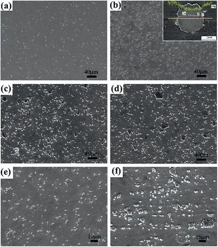
Fig. 9. Scanning electron microscopy (SEM) micrographs displaying the particle dispersion in CPP reinforced ZK60A NCs (a) 2.5 wt.%, (b) 5 wt.%,(c) 7.5 wt.%, and (d) 10 wt.%; SEM images depicting the particle accumulates in the NCs containing (e) 5 wt.% and (f) 10 wt.% CPP reinforcement at a higher magnification; the insert image in (b) shows the profile of the element around the interface between ZK60A alloy and CPP reinforcement particles [152].
Hou et al. [162] prepared MWCNTs reinforced Mg-6Zn NC using a powder metallurgy process and an aging treatment post-process. Following post-processing, an extensiveβ′1phase with a coherent relationship to the matrix precipitated and significantly reduced the lattice distortion of the Mg-based matrix. Results showed that the TYS and UTS of the fabricated NCs with different concentrations of MWCNTs were remarkably higher than the Mg-based matrix, as shown in Fig. 11(a,b) [162]. The dispersed CNTs induced a greater number of fine precipitates, which decrease the effective planar interparticle spacing of phases, resulting in a more effective impeding effect on dislocations; on the other hand, the bonding between CNTs and matrix is strengthened by the plane of Mg-based matrix being embedded in CNTs,forming a partially inserted interface, allowing efficient load transfer from matrix to CNTs (Fig. 11c). Fig. 11d illustrates how the solute atoms in the matrix can cause significant lattice distortion and serve as centers for electron and phonon scattering (changing the motion direction of electrons and phonons while decreasing their energy) [162]. The precipitation ofβ′1phase and the distributed reinforcing particles also act as a key factor in the age-strengthening effect of Mg-6Zn/MWCNTs NC. The solute atoms are greatly reduced during phase precipitation, and the crystal lattice tends to be perfect.

Fig. 10. (a) Schematic representation of fabricating CNT-reinforced Mg nanocomposite (b) TEM micrograph showing “connecting bridge” which is the penetration of CNTs reinforcements that into adjacent magnesium, (c) magnified area A shown in (b) that represents the interface of matrix/reinforcement, (d)Engineering stress-strain curves of magnesium and Mg-CNTs NCs, (e) True stress-strain curves of magnesium and Mg-CNTs NCs, (f) The strain hardening rate Θ as a function of true strain [157].
Shahin et al. [133] developed GNP-reinforced Mg-Zr NC utilizing the traditional sintering process. The high-energy ball-mill processing could result in a uniform dispersion of magnesium, zinc, and GNP particles in NC. The microstructure analysis showed that GNP-reinforced Mg-Zr NC has the smallest grain size (16 μm), in comparison with Mg-0.5Zr alloy (23 μm) and monolithic magnesium (43 μm). The evaluation of mechanical properties revealed that the NC’s ultimate compressive strength (UCS) is 91% higher compared to the monolithic Mg (219 MPa). This substantial improvement in mechanical properties could be due to the atomic size difference between Zr and Mg, leading to an interstitial solid solution effect. The elastic moduli of MMNCs, as determined from nanoindentation, showed a 40% increase in comparison to monolithic magnesium due to load transfer from the matrix to the harder reinforcing particles.
3.8. Difference in elastic modulus strengthening
A difference between the elastic modulus of the matrix and reinforcing particle materials could result in the generation of dislocation in NC during plastic deformation because of the non-uniform slip of reinforcement particles [154]. It is worth noting that whiskers, which have an elongated geometry with a high aspect ratio, display much higher strengthening due to the difference in elastic modulus compared to spherical reinforcing particulates[163,164]. Nguyen et al. [136] fabricated AZ31B magnesium alloy and AZ31B-3.3Al2O3–Cu NC utilizing DMD process and a hot-extrusion post-processing.They reported a remarkable enhancement in 0.2% CYS in NC compared with the matrix which could be the result of the difference in the matrix/reinforcing particle elastic moduli.
Tu et al. [165] produced Mg alloys with high modulus and strength. They exhibited that introducing Ge to the matrix Mg-Gd-Ag-Mn alloy might enhance both the elastic modulus and the strength of the alloy. Among the Ge alloys, Mg-10Gd-1.5Ag-0.2Mn-3.5Ge alloy had the best overall mechanical characteristics, with elastic modulus (E), ultimate tensile strength (UTS), and EL of 51 GPa, 423 MPa, and 10%, respectively.They also created a new as-cast Mg-Y-Zn-Al-Li alloy with elastic modulus of 52.9 GPa [20,164]. Furthermore,Liang et al. [75] created a carbon nanotube (CNT) reinforced Mg-based composite using a combination of friction stir processing and ultrasonic aided extrusion. The results demonstrate that when in comparison with AZ91D alloy, the UTS,yield strength, and E of 1.0 vol.% are much higher. The percentages of CNTs/Mg NC increased by 25.5%, 13.5%, and 12.2%, respectively.

Fig.11. Stress-strain curves of Mg-6Zn matrix and MWCNTs reinforced Mg-6Zn NCs(a)before and(b)after aging treatment,and(c)Schematic illustration of dislocations pinned by short β′1 phases precipitated around MWCNTs and long β′1phases precipitated without reinforcing particles nearby, and (d) Schematic illustration of scattering of electrons and phonons by lattice distortion induced by solute Zn atoms during heat transfer process [162].
3.9. Computing total strengthening effects
To find the overall strengthening effect of reinforcements,several methods are discussed in this section. These methods are applied for the quantitative identification of reinforcing particles’ contribution to the resulting MMNCs’ strength[51,133,166]. Synergistic reinforcement mechanisms may occur based on the contribution of various strengthening mechanisms. These include three methods; 1) sum of contributions,2) Zhang and Chen, and 3) Clyne [128]. Hereafter is a short explanation for each method.
3.9.1. Sum of contributions
A simple method for identifying the overall strengthening effect of reinforcement in a composite is directly adding different contributions together. This route to predict the overall strengthening effect is usually inaccurate in most cases, especially when there are multiple factors influencing the strength because it ignores the influence of different mechanisms on one another and assumes that each factor behaves independently. This method is mathematically represented by the formula below.
3.9.2. Zhang and Chen method
This method only takes into account the Orowan, loadbearing, and DTE strengthening mechanisms. So, the precision of this method is limited as some important and proven strengthening mechanisms, such as DEM, work hardening, and Hall-Petch strengthening are not considered. Cao[167] used the Zhang and Chen method to predict the resulting strength of the NC and reported a difference between experimental and theoretical results. In this instance, the difference was because the method does not consider the influence of NP-stimulated refinement of the grains. Hereafter, the mathematical explanation of the method is presented [125].
3.9.3. Modification of Clyne method

Fig. 12. Comparison of calculated overall strength using different methods and experimental results for Y2O3 reinforced Mg NCs(a)Different unimodal NCs, and (b) YS against reinforcement concentration (%) [125].
A more precise method to calculate the overall strengthening effect of reinforcement in the composite is presented by Clyne et al. [168]. Their proposed method considers the contribution of various synergistic strengthening mechanisms to the YS of the MMNCs as the square root of the sum of squares, as shown below.
whereσy,Δσm0andΔσare the YS of the reinforced and non-reinforced matrix, and the Matrix’s total increase in YS,respectively. It should be noted that the work hardening influence during extrusion or pressing is not significant for a matrix with fine grains and thus can be overlooked.
As Fig. 12a displays, the theoretical estimations are higher than the experimental results in most cases [125]. It could be attributed to some weaknesses introduced during the composite fabrication process, such as reinforcement particle agglomeration, contamination, and forming porosity, which all have a negative influence on strength and are not considered by the equation. Fig. 12 shows that the results of the Zhang and Chen and the modified Clyne methods are more like the experimental results. Fig. 12b depicts the YS obtained from models and values from experiments against the concentration of reinforcements for the Mg-Y2O3NC[125].
It is worth noting that the Orowan and dislocation strengthening effects could both be significantly enhanced by a reduction in reinforcement particles’ size and an increase in their concentration. As the concentration of NPs added is normally low, the effect of the load transfer mechanism is not considerable. To have a greater enhancement in the performance of the NP-reinforced MMNCs, a high concentration of nanoparticles should be used,along with performing a post-processing deformation. If the added NPs can be dispersed uniformly in the matrix, this can strengthen the grain refinement, the load-bearing mechanism, and the Orowan strengthening effect [144].
The Orowan strengthening is stronger than the DTE influence for composites where the process temperature is at RT, whereas for those with a process temperature above RT(up to about 300oC), the DTE effect becomes more remarkable compared to the Orowan strengthening. The reason for this is that dislocation annihilation brought on by increased atomic diffusion at elevated temperatures reduces the number of dislocations introduced into the structure (less barrier to diffusion because of Arrhenius behavior). As a result, the Orowan effect produces fewer dislocations than processes that occur at RT, which lowers the Orowan strengthening effect and reduces dislocation interactions. On the other hand, as the temperature rises, the impact of DTE between the reinforcement and matrix becomes more significant. This occurs because of the matrix and particle expansions diverging more as temperature rises,which raises the dislocation density close to the matrix/particle interface. It is noteworthy that the loadbearing effect is insignificant for all composites because the particulate percentage is so low and does not significantly affect the overall strength [125]. The enhancement mechanism on the mechanical characteristics of Mg-based NCs is reported in Table 3. It is well understood that using traditional metal developing processes like extrusion as secondary processing of discontinuously strengthened composites may result in particle (or whicker) aggregates being broken up,porosity diminished or eliminated, and bonding enhanced, all of which contribute to better mechanical properties of MMCs.In the case of Mg MMC, hot extrusion is employed as secondary processing after sintering. This mechanical alloying provides critical and distinguishing characteristics, such as a large number of crystal flaws in the particles, as a result of intense plastic deformation. This crystal defect includes a significant amount of internal stored energy, which promotes recrystallization and the formation of second phases precipitates during post-processing [28]. It is always carried out at temperatures considerably greater than the material’s recrystallization temperature [29]. For the as-extruded composites, dynamic recrystallization (DRX) occurred and concluded throughout hot extrusion. The use of DRX lead to significant grain refinement [30]. It is worth mentioning that hot extrusion improved additions distribution and refined matrix grains significantly. The reinforcement-matrix interface has been altered. Extrusion changed the distribution of the second phases as well as their size. Second phase bands were also formed along the extrusion direction. All of these variables can affect the mechanical properties of composites [30].

Table 3 Production methods and tensile properties of magnesium-based NCs.

Table 3 (continued)
4. Creep behavior
Another representative mechanical characteristic that can be used to assess the suitability of Mg alloys in practical usage is creep resistance [174]. One of the most crucial mechanisms influencing the creep performance of Mg alloys is diffusion [175]. Although the activation energies for diffusion and creep behavior have different physical meanings, the activation energies value can be used to relate the creep resistance of Mg alloys to their diffusion data analysis [176].The slow plastic deformation under constant applied stress at temperatures higher than 0.4Tmis referred to as creep,where Tmis the absolute melting temperature. It should be noted that it can happen at any temperature and under any stress, but it becomes significant at temperatures higher than 0.4Tm[177,178]. Creep can result in a material failing at stresses below its YS. It is well known that one of primary problems preventing the widespread use of Mg-based alloys is their inadequate high-temperature creep resistance. This is particularly a concern for automotive powertrain components,which frequently experience prolonged exposure to stresses and temperatures higher than 473 K [178]. Metals and alloys go through three stages of creep deformation: primary creep,secondary creep, and tertiary creep [4,179]. Secondary creep,also known as steady-state creep, is particularly important in automotive powertrain applications. It is widely accepted that the secondary creep rate(denoted ´ε)for Mg and Mg-Al alloys shifts based on the equation shown below in the stress and temperature ranges of interest to automotive use (i.e. stress(σ)= 20 MPa to 100 MPa and temperature (T) = 100 °C to 250 °C) [180–186].
In this equation,Ais a constant related to the material type,nis the stress exponent,Qis the creep activation energy, andRis the gas constant, which is 8.314 J/mol K. According to the above-mentioned formula, the slope of the log´εagainst logσplot at a given temperature is the stress exponent n, and an Arrhenius plot(ln´εversus 1/T)at a specific stress level will yield the apparent activation energyQ. ThenandQvariablescould be utilized to deduce the primary creep mechanisms for different stress and temperature conditions. It is generally known thatn= 3 andn= 5 are related to the viscous glide of dislocation and the dislocation climb at high temperature,respectively.Thus,the viscous glide of dislocations and/or the dislocation climb should be related to the current creep deformation process for these four materials at 240 °C [187].Diffusion controls creep rates at high temperatures, which is also as vacancy creation occurs. This vacancy formation allows dislocations to overcome impediments by climbing off of their slip planes via vacancy diffusion or cross-slip. The two different vacancy diffusion mechanisms—volume or lattice diffusion at high temperatures and dislocation core or pipe diffusion at lower temperatures—are typically used to produce this climb motion [188]. According to Somekawa et al. [189],pipe diffusion for the AZ91 alloy changed to lattice diffusion at an activation energy of 113 kJ/mol. As a result, the activation energy of unreinforced alloy, which is 116 kJ/mol ± 3 kJ/mol, indicates that pipe diffusion transforms into lattice self-diffusion for the alloy. Nevertheless, the diffusion process for NCs, continues to be pipe diffusion because the values are below the crucial value for change, which is 113 kJ/mol[190]. On the other hand, climb is a diffusion-driven process that is more likely to take control at high temperatures [191].According to Mahmudi et al. [192], the dominant mechanism in the creep of the AZ91 + (0.5 ± 2)Sn alloy at temperatures between 423 K and 523 K and stresses between 150 and 650 MPa is dislocation climb, and the climb velocity is governed by the lattice and pipe diffusion of Mg.

Table 4 Creep-resistant Mg alloys and composites in the relevant temperature range.

Fig. 13. The distribution of the rate-controlling creep mechanisms in a temperature range of 100 °C–350 °C and stress range of 20 MPa–120 MPa for Mg alloys [204]. ∗indicates the specified creep mechanism not fitted in the regime.
It is worth noting that creep-resistant Mg-based alloys should be used as the matrix material to achieve the best creep properties. Table 4 lists creep-resistant magnesium alloys for different non-RT conditions. The alloys mentioned in the table suggest metrics for producing creep-resistant Mg NCs [193]. It should be mentioned that Mg alloys are classified based on their base alloy composition. The use of Mg-Al based alloys such as AZ91, AZ61, and AZ31 is restricted to working temperatures up to 120 °C because of a major drop in mechanical strength and creep resistance [4,194]. These alloys also demonstrate good castability and significant mechanical characteristics.Alloys from the Mg-Al-Mn(AM),Mg-Al-Zn (AZ), and Mg-Al-Si (AS) series function weakly above 130 °C [195]. Because of the thermal softening, coarsening,and dissolving of theβ-phase, mechanical strength and creep resistance decrease at greater temperatures. At high temperatures, grain boundary sliding causes a decrease in mechanical strength because theβ-phase has a lower melting point[196,197]. The main elements that control the strengthening of alloy in solid solution are its diffusivity and solubility. Because of the great diffusivity of the Al solute, the Mg-Al series exhibits lower creep resistance. Zinc has a greater solubility in Mg than Al, which increases strength and reduces creep. Because RE elements are greater in size compare to Mg, they have lower diffusivity [198]. Due to the formation of the stable ternary eutectic compound MgZnRE, RE elements can improve cast-ability and creep resistance [199].Wang et al. [200] proved that solute impurity diffusion in Mg cannot affect the creep characteristics of Mg alloys. As a result,diffusion of Mg and/or alloying atoms has been proposed as a cause for their creep behavior via impeding dislocation movement. The associated diffusional creep mechanism could be classified into three categories: pipe diffusion [178], Coble creep [201], and Nabarro-Herring (N–H) creep [202], which occur via the crystal lattice, only along grain boundaries, and preferably along dislocation cores. However, most researchers studied the compressive and tensile creep characteristics of Mg alloys at moderate temperatures [178,203], which does not match the conditions for diffusional creep. Based on these concepts and the reconstructed rate-controlled creep mechanism for Mg alloys in Fig. 13 the diffusional creep mechanism appears to be secondary in importance when compared to other creep mechanisms [204].

Fig. 14. For indentation (a) parallel to the ED and (b) perpendicular to the ED, the stress state and crystallographic orientation are depicted in relation to indentation direction, and AFM photographs of the indentation area proving twinning activity for indentation, (c) along the ED and (d) perpendicular to the ED, and (e) optical micrograph of the indentation area illustrating slip lines and mechanical twins for indentation perpendicular to the ED are also highlighted[191].
Diffusional creep may happen at low temperatures(approximately 0.4 Tm) and high stresses in addition to rather high temperatures. Pipe diffusion is thought to have a somewhat greater activation energy than Mg grain boundary diffusion.In pure Mg, there exists only one group of activation energy for grain boundary diffusion (92 kJ·mol-1) [176]. At low temperatures and high stresses, the creep processes of AZ61 alloys[205], Ca and Sb added AZ91 alloys [205], and AZ81 alloys [206] were all proposed to be pipe diffusion since the mean creep activation energies were marginally greater than the activation energy for pipe diffusion. Similarly, pipe diffusion was inferred as the dominant creep mechanism of ascast MRI153 Mg alloys [207]. Nami et al. [208] validated the similar pipe diffusion regulated creep rate mechanism in Sncontaining MRI153 Mg alloys. However, by increasing applied loads, some Mg alloys were able to switch from lattice diffusion to pipe diffusion controlled creep mechanism[206,209]. All of these researches show that understanding the correlation between diffusion data and creep resistance of Mg alloys aids in the design of superior creep behavior in Mg-based alloys [176].
The nanoindentation method could be used to investigate the material’s nanoscale creep behavior [213]. This method can probe the material’s mechanical properties locally because it may distinguish between micro features (such as precipitates, grain boundaries, and so on) in the material [214]. Nautiyal et al. [191] investigated nanoindentation-induced creep in pure Mg as well as solution-treated and peak-aged extruded AZ61 alloy. As shown in Fig. 14, the stresses used in nanoindentation are tri-axial, in contrast to those used in conventional tensile or compression mechanical tests, which are uniaxial [191]. A combination of various deformation mechanisms is possible based on the type of stress in relation to crystal orientation,as shown in Fig.14a,b.A sign of twinning activity could be observed along one of the edges of the triangular indentation in the atomic force microscopy (AFM)image of the indentation region displayed in Fig. 14(c,d).However, because the alloy has a ring-like texture, there are multiple possible orientations for the c-axis for indentation perpendicular to ED (Fig. 14(e)) [191]. As a result, a combination of slip and twinning is predicted. This figure further confirmed the presence of twinning and slip as main mechanism for indentation creep [191]. The equation used in a depth-sensing indentation experiment is as follows [215].

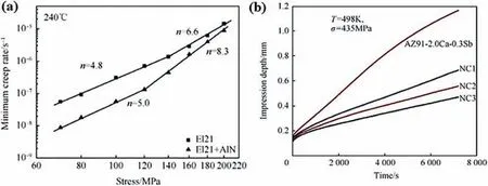
Fig. 15. (a) Double logarithmic plot of minimum creep rate versus applied stress from tests performed at 240 °C [216], and (b) Typical impression creep plots for AZ91–2.0Ca-0.3Sb alloy and it’s three SiC reinforced NCs characterized at 435 MPa stress and 498 K temperature displaying the changes of impression depth against time [190].
Katsarou et al. [216] investigated the creep response of 1 wt% AlN NPs reinforced Elektron 21 (El21) Mg alloy (Mg-2.85Nd-0.92Gd-0.41Zr-0.29Zn) fabricated using ultrasoundassisted stirring.In this research,the compressive creep experiment was performed on a lever-arm testing machine at 240°C with constant stresses ranging from 70 MPa to 200 MPa.Based on experiments on the matrix(El21 Mg alloy)and AlN reinforced El21 composite at 240 °C, they presented their results in a log-log plot which shows the changes of minimum creep rate against applied stress depicted in Fig. 15a [216].A bi-linear trend was seen; in which at applied stresses lower than about 120 MPa the stress exponent (n) was 4.8 for the matrix and 5.0 for the composite while for the stress values higher than 120 MPa the stress exponent was 6.6 for the matrix and 8.3 for the composite. The study’s findings revealed that the reinforced composite has a lower minimum creep rate than the monolithic matrix at all applied stresses and the difference decreases with increasing stress. Ganguly et al. [190] investigated the microstructure and impression creep properties of AZ91–2.0Ca-0.3 Sb magnesium alloy and its three SiC-reinforced NCs with 0.5,1,and 2 wt%reinforcement concentration. In their impression creep experiment, the temperature range was between 448 K and 523 K and the stress range was between 300 MPa and 480 MPa, and the test duration was 2 h. The creep resistance of NCs was higher than the matrix and the highest creep resistance was seen in 2 wt% reinforced NC (Fig. 15b) [190]. They also proposed that the alloy and NCs’ governing creep mechanism is dislocation climb controlled by pipe diffusion. This climb motion is usually accomplished through one of two vacancy diffusion mechanisms: volume or lattice diffusion at high temperatures and dislocation core or diffusion along the dislocation (i.e.pipe diffusion) at low temperatures [37,217]. In this respect,pipe diffusion-climb controlled dislocation creep is a form of dislocation creep in which the creep rate is controlled via climbing dislocations and atom diffusion happens in dislocation pipes [218]. Nami et al. [205] examined the influence of Ca incorporation on the microstructure and imprint creep performance of cast AZ61 Mg alloy. The enhancement in creep characteristics is related to a reduction in the quantity of Mg17Al12phase and the development of the extremely thermally stable (Mg,Al)2Ca phase. The findings of the creep study indicate pipe diffusion-climb regulated dislocation creep as the dominant creep mechanism, and Ca introduction has no influence on this mechanism [205].
The presence of nanoparticles can efficiently help to enhance the creep behavior of the Mg-based NCs at high temperatures through the prevention of grain boundary sliding(GBS) by pinning the grain boundaries. It should be noted that GBS is one of the primary mechanisms of creep failure in metals and alloys,particularly at elevated temperatures.For applications where a high creep resistance at high temperatures is required,Mg NCs with NPs decorated at grain boundaries may be a favorable option. Through precipitation hardening,precipitates would aid in making the materials stronger.However,when the particle size exceeds the size of the matrix grains (as in ultrafine/nanocrystalline-grained materials), the Hall-Petch effect will predominate, making the precipitates’contribution to the material’s creep resistance less significant.As a result, fine precipitates achieve the greatest strengthening. When exposed to high-temperature creep, those equilibrium low-melting temperature intermetallic phase precipitates may become thermally unstable in the matrix. At high temperatures, the precipitates either coarsen or dissolve in the matrix. Externally added NPs, on the other hand, are insoluble in the matrix and resist dissolution and coarsening. This aids in the retention of strength (and creep resistance) at elevated temperatures [193]. Yang et al. [187] dispersed 1%of AlN/Al nanoparticles in El21 magnesium alloy utilizing a novel stirring technique called the high shearing dispersion technique (HSDT). Microstructure evolution of as-cast, T4,and T6 conditions for the matrix and NC are shown in Fig.16[187]. The as-cast El21 is consisted of Mg3RE and Mg12Nd,while as-cast NC (El21 + 1% AlN/Al) including Mg3RE and Al2RE phases. However, some Mg3RE were dissolved within the matrix during T4 modification, which caused RE to enter solid solution. According to the results of the creep evaluation, the T6 heat treatment decreased NC’s creep resistance while increasing the creep resistance of the matrix. This may be due to the fabrication of plate-like Al2(Nd, Gd) (Al2RE)precipitates, which led to a decrease in the amount ofγ’’andβ´precipitates in T6-treated NC after aging. It was also observed that the T6-treated El21 matrix has a lower minimum creep rate with a shorter duration of secondary creep stage compared to the T6-treated nanocomposite at elevated temperatures.This might be a result of precipitates over-aging and the thermal stability of the Al2RE particles. Whether in the as-cast or T6-treated conditions, AlN/Al reinforced NC demonstrated a much longer duration of secondary creep than the matrix. The formation of the particle/plate Al2RE phase and the incorporation of AlN NPs were identified as the possible causes of the improvement [187].

Fig. 16. Illustration of the microstructure evolution of El21 matrix and 1% AlN/Al reinforced nanocomposite NC (El21 + 1% AlN/Al): (a) as-cast matrix, (b)T4-treated matrix, (c) T6-treated matrix, (d) as-cast NC, (e) T4-treated NC and (f) T6-treated NC [187].
Ferkel et al. [219] extruded pure Mg and two types of 3 wt% SiC NPs reinforced NCs at 593 k and evaluated their RT and high-temperature mechanical properties. The difference between the two types of NCs was their preparation method,with one being mechanically ball-milled and the other being traditionally mixed. At all RT, 373 K, 473 K, and 573 K testing temperatures, the ball-milled NC had the highest strength but also the lowest formability. Furthermore, at 473 K, a remarkable difference in creep response was observed on the ball-milled NC. The concentration of reinforcing NPs can improve NC strength by assisting with Hall-Petch, efficient load transfer, and the Orowan strengthening mechanisms. Nevertheless, there is normally some limitation to increasing the content of NPs in the matrix, as the concentration of the reinforcing particles in the matrix is always constrained in some way. Due to the high surface-to-volume ratio of the NPs and strong Van-der Waals forces that pull the particulates together,agglomeration of the particles in the matrix is a significant problem that limits the NP concentration. If agglomeration occurs, the particles are not regarded as nanosized but rather as micron-sized.As a result,the particle’s effectiveness in various mechanisms of strengthening is diminished. This has a negative impact on the material’s ability to resist creep. If the reinforcing particles are not distributed evenly throughout the matrix, there are typically some voids. The fabrication of the Mg NCs in such a way as to guarantee an even distribution of the NPs throughout the matrix may therefore be challenging[193]. Kumar et al. [220] used a combination of stir casting and ultrasonic processing to produce 2 and 5 wt% aluminareinforced Mg-4Al-1Si (AS41) Mg alloys. The results of their indentation creep experiment with 109, 125, and 140 MPa stresses at 448, 473, 498, and 523 K temperatures are shown in Fig. 17 [220]. The 5 wt% Al2O3reinforced nanocomposite has the highest creep resistance. Additionally, rising temperatures and stress levels accelerate the creep rate. As cast AS41 alloy and NCs exhibited an accelerated creep rate at 250 °C,as well as a smaller primary stage in their creep curves at this temperature compared to other temperatures.
Internal stresses produced by twin growth exceed the YS of the matrix and are thus accommodated by plastic deformation processes such as slip [221]. Through its restriction on twin nucleation and growth, NP loses some of its ability to enhance stress,which could lead to a reduction in yield stress.In other words, an increase in strain rate reduces the strengthening effect of NPs on grain boundaries in terms of retarding twin nucleation/growth.NPs can influence twin nucleation and growth,increasing the number of smaller twins[35].Twin growth can be completely stopped (in the case of large precipitations) or the growing twin can swallow up (engulf) the precipitates (in the case of small precipitations), leading to particle rotation but not necessarily particle shearing, depending on the relative sizes of the twins and the size/distribution of the NPs [193].
Fig. 18a compares alloy’s the minimum creep rate to that of other creep-resistant Mg alloys, comprising Mg-RE-based cast alloys and benchmark die-cast Mg alloys [222]. Despite its low RE content, the alloy possesses adequate creep resistance when compared to other Mg-RE-based cast alloys in the same creep situation [1,11,27,29,222]. The alloy has approximately the same minimum creep rate at 200oC/60 MPa as the typical WE43 alloy, indicating that both alloys have equal creep resistance. As a result, the alloy is expected to be a suitable replacement for WE43 alloy in a variety of applications. Furthermore, the alloy’s lowest creep rate is nearly an order of magnitude less than that of common QE22 and EV31 [1,11,27,29,222]. Of course, the alloy’s creep properties are lower than those of heavy RE alloys including Mg alloys. On the other hand, the alloy has a greater advantage over die-cast Mg alloys, and its lowest creep rate is significantly lower than the benchmark die-cast Mg alloys. The creep resistance of cast Mg alloys is determined by the subsequent particle strengthening and solid solution hardening.Fig. 18b presents the atomic misfit and atomic radii of regularly utilized solutes and Mg [222]. Since the atomic radii of RE atoms are greater than those of Mg atoms, it is fair to believe that RE atoms are responsible for the larger order strengthening that of RE-free atoms [5,10]. Furthermore,the majority of RE solutes have a higher atomic misfit with Mg solvent, as well as a greater solid solution in Mg, which significantly decreases the creep rate [5,10,222]. The superior creep resistance of the Mg-based alloy in comparison to other creep resistant Mg alloys, including recognized Mg-RE-based cast alloys and die-cast Mg benchmark alloys, is because of both thermally stable intermetallic phases and greater stable order strengthening owing to RE solutes with large atomic radii at high temperatures.
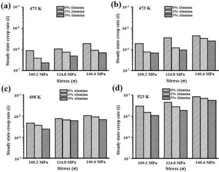
Fig. 17. A creep rate comparison between as-cast AS41 alloy versus alumina-reinforced NCs under various stresses at (a) 448 K, (b) 473 K, (c) 498 K, and(d) 523 K temperatures [220].

Fig. 18. (a) A comparison of the minimum creep rate between the alloy and some creep-resistant Mg alloys including Mg-RE-based cast alloys and benchmark Mg alloys produced by die casting, and (b) A comparison of atomic misfit between commonly adopted solutes and Mg and their atomic radii [222].
5. Fatigue properties
In the modern manufacturing field, long-life service and exceptional dependability was recognized as both an urgent need and a future aim. Fatigue damage is undoubtedly posing a danger to long-life service reliability, particularly the very-high-cycle fatigue (VHCF) issue [223,224]. The veryhigh-cycle regime is a range of cyclic loading that exceeds 107cycles, and fatigue failure in such a regime is classified as VHCF failure, also known as gigacycle fatigue failure[223]. It is well known that fatigue failure can occur under conditions of comparatively low cyclic stress below the usual fatigue limit after 107loading cycles (i.e., in the very-highcycle regime) [225,226] As a result, the VHCF failure issue has garnered widespread concern and has evolved into a focus of investigation. It is related not just to the broad engineering application, however to the scientific attraction that has developed over the last two decades.It has often been demonstrated that the fracture initiation stage consumes almost all of the total fatigue life in VHCF failure [227,228]. As a result, the fracture initiation process is now recognized as the most important aspect of VHCF failure in terms of scientific importance [229].
Because of their unique properties, Mg-based composites have proven to be a promising material for wide range in aerospace, automotive, defense, biomedical and consumerrelated applications. A cardiovascular stent experiences cyclic tension loads due to heartbeat,and femoral implant endure axial compressive loading and cyclic bending throughout normal walking and running[230].These loads are repetitive and variable, with one million cycles per year [231].
In their lifetime, the Mg-based MMCs used in various applications are subjected to fatigue and dynamic load. Therefore,a systematic evaluation of the behavior of the parts under the same circumstances is necessary. Multiple variables influence the fatigue performance of Mg-matrix alloys and composites, comprising microstructure, alloying elements, loading circumst- ances, surface modification, reinforcing properties,and fabrication process [232].
Ochi et al. [233] looked into how the concentration of Al2O3short fibers affected the high-cycle fatigue characteristics of the AZ91D alloy. Their findings demonstrated that the matrix’s fatigue strength had been increased by the addition of reinforcement. Additionally, they demonstrated that the agglomerated reinforcing fibers are the origin of the composite crack. Fatigue crack almost originates along the highest shear stress (i.e. Mode II crack) and subsequently deflects outward of the original cracked grain. It deflects perpendicular to the distant greatest primary stresses (i.e. Mode I crack).Evidently, the grain boundary hinders the propagation of such micro-cracks. In this situation, particle size may influence microstructural fatigue parameters, and grain refinement could boost fatigue strength [229]. Wrought Mg alloys have better mechanical characteristics compared to cast alloys under cyclic and quasi-static loadings, which makes them desirable candidates for load-bearing parts [234]. Following these deformations, the c-axis of the Mg unit cell reorients itself to be parallel to the specific deformation direction, resulting in a strong basal texture [234,235]. It is believed that this texture evolution in the microstructure could be caused by rotational dynamic recrystallization (DRX), which is induced by the activation of non-basal slip systems such as pyramidal II
By using a solidification process followed by hot-extrusion,Srivatsan et al. reinforced AZ31 Mg alloy with 1.5 vol.% alumina’s [236] and 1.0 vol.% CNTs [237]. The AZ31 matrix’s endurance limit was 81 MPa at 106cycles. With the incorporation of 1.5 vol.% of alumina, the endurance limit was increased by 36% to 110 MPa, and by 40% to 113 MPa with the incorporation of 1 vol.% of CNTs. They claimed that by delaying crack initiation and preventing crack growth within the matrix, the addition of NPs could enhance the fatigue properties of the Mg-based matrix. Improvement of the NC’s fatigue resistance compared to the matrix could be due to several reasons. The agglomeration of reinforcing particles,which is a site for the initiation of cracks, could be avoided by setting the proper parameters for the fabrication process of NCs [236,237]. Dislocation densities, pores, and inclusions introduced into composites during the fabrication process all have a remarkable influence [238]. When compared to a non-reinforced matrix, the components of NC underwent less strain because the high-strength addition carried most of the load at the fine microscopic scale. Grain refinement has a noticeable influence on delaying the onset of cracks, improving cyclic fatigue life in the process [236,237,239]. The fabrication of NCs under the appropriate circumstances can lead to better compatibility between the components of a composite (wetting between NPs and the matrix) and make it easier to transfer applied loads from the matrix to high-strength reinforcing particulates without de-bonding [240,241].
The high cycle fatigue curves (stress amplitude-life) of pure Mg, Mg/2.5 wt.% HA, and Mg/5 wt.% HA are shown in Fig.19a-c[242].As compared to pure Mg specimens,Mg/2.5 wt.% HA and Mg/5 wt.% HA exhibit better fatigue characteristics, as shown in Fig. 19a. HA additions may serve as crack propagation barriers, leading in increased fatigue life [30].Furthermore, the presence of nanoadditions in the matrix may lead to cleavage fractures emerging in front of fatigue cracks,spreading stress concentrations and converting the plane stress state on the crack tip to plane stress one [80,84]. The quantity of YS and UTS, respectively, influence the start of plastic deformation and crack initiation. The normalized stresses against the number of cycles to failure are shown inFig. 19b,c and c to study the effect of yield stress and ultimate tensile strength on high cycle fatigue behavior. The curves show that YS improvement may be an important variable in improving the fatigue life of composites. The fatigue life of the composites increased at lower stress amplitudes when compared to pure Mg specimens. Because reinforcing particles can operate as stress concentration points, local plastic deformation may occur near them at greater stress amplitudes,inducing fracture initiation in the composite and, as a result, reducing the good influence of additions.Fig.19d depicts a schematic illustration of fatigue damage in T4 and T6 WE43 Mg alloys [243]. As a crack caused by basal slip propagates to the grain boundary along the cleavage plane, stress concentration happens at the grain boundary. Dislocation on the properly oriented cleavage plane is initiated, and the fracture propagates forward along the new cleavage plane. It may be developed that basal slip is the primary mechanism of fatigue damage in the T4 alloy. Because of the impediment influence of precipitation on basal slip and twin growth, a significant number of pyramidal slip is activated, promoting the slow enhance of plastic strain amplitude under cyclic deformation. At the same time, due to the presence of PFZ with less strength in comparison to the grain, the crack develops easily along the grain boundary(Fig. 19e) [243].
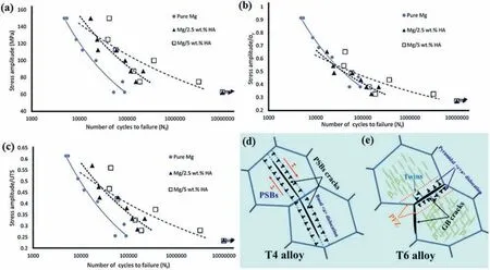
Fig. 19. High cycle fatigue curves of the Mg/HA composite specimens: (a) stress amplitude versus the number of cycles to failure, (b) normalized stress amplitude (to yield stress) versus the number of cycles to failure, and (c) normalized stress amplitude (to UTS) versus the number of cycles to failure [242].Schematic diagram of fatigue damage of T4 and T6 alloys: (d) T4 alloy; (e) T6 WE43 magnesium alloys [243].
Forging and rolling are examples of secondary postprocessing that aid in deagglomerating, homogenizing distribution, removing porosity, and strengthening interfacial bonds[14]. The pores tend to be sites of origin for cracks, and they reduce the time for crack initiation and the material’s fatigue life. In this regime and for defect-free materials, the fatigue crack initiation step is expected to take up to 90% of the fatigue life at low-stress amplitude compared to the crack propagation step[244].Nonetheless,the existence of microstructure defects, such as particulate accumulation, pores, and microcracks can shorten the time for crack initiation, resulting in decreased fatigue resistance[245].Jabbari et al.[239]demonstrated that using a post-process application of plastic strains(such as a closed-die forging process or extrusion) can enhance the NC’s high cycle fatigue behavior. In this respect,Goh et al. [123] studied the fatigue resistance of the extruded monolithic magnesium and its MWCNTs reinforced NC. According to their findings, the NCs had a shorter fatigue life than the matrix in the same range of applied plastic strain.The existence of cavities and particle agglomeration caused a reduction in fatigue life. Similarly, Anes et al. [246] investigated the fatigue performance of the magnesium alloy extrusion in both high and low cycle regimes during fully reversed axial tension-compression, torsional, and multiaxial loads with proportional and 90°out-of-phase non-proportional circumstances. The findings showed that the loading path had a major effect on the material’s fatigue strength in the high cycle fatigue (HCF) regime at the same equivalent stress.Fatigue cracks typically form at cyclic slip bands and twin boundaries[232,246],typically at stress concentration sites including geometric discontinuities like corners and notches, as well as manufacturing imperfections such as inclusions,pores,and shrinkage voids developed during casting and scratches formed during the machining process [247,248]. The initial stage of crack propagation is highly susceptible to microstructure, and fatigue crack propagation occurs at an exceedingly slow and variable rate. It needs to be highlighted that fatigue fracture nucleation and early propagation happen in the internal vacuum-like environment at the specimen interior for internal failures. It is determined that fatigue cracks develop through slip bands along the basal plane, leading to the production of a fatal facet on the fracture surface [229]. Fatal facets occur at crack initiation locations, and the initiation mechanism is highly crystallographic on planar slip systems along the direction of highest shear stress [229]. Likewise,Sabet et al. [249] evaluated the HCF characteristics of the Mg/HA biocomposite containing 2.5 and 5 wt% HA during rotating-bending loading. The results reveal that biocomposites outperform commercially pure Mg extrusion in terms of overall HCF performance. In all stress amplitudes, the fatigue life of the Mg/2.5 wt% HA composite was greater than that of pure Mg. However, with greater stress amplitudes, HA powder agglomerations may produce stress concentration and boost the crack initiation stage. The S-N curves with normalized stress magnitudes to yield stress show that increasing yield stress in composites improves overall fatigue life in comparison with pure samples.

Fig. 20. Potential and current uses of Mg-based alloys and nanocomposites [2].
6. Potential applications
The use of NPs to reinforce magnesium matrix composites is not yet widespread. Fig. 20 lists some of the current commercial uses for magnesium and its alloys [2]. Mg is the lightest metal and is used in a variety of applications that call for light weights due to its outstanding low density. It works in power tools, automotive, and aerospace devices [250]. In the automotive sector, a 10% weight reduction will result in a 7% reduction in fuel consumption [251]. There would be a weight reduction of 22–70% if Mg and Mg-based composites can replace the currently used automotive materials[252].Some AZ and AM alloys with high strength and formability at RT have been used as sheets or other car parts [144]. Some of the Mg-based materials that are used in the aerospace industry are engine castings parts, casting components of the transmission system, and landing gears. Also, Mg is widely used in the helicopter industry for the production of different parts, such as gearboxes. Despite its lightweight, airplane manufacturing companies do not use Mg for structural applications because of its high corrosion rate [253].
Mg has found applications in electronics and power tools.Mg dissipates heat about 100 times better than plastic [254].Aside from that, Mg has a lot of potential in electronics applications due to its strong electromagnetic shielding performance, excellent vibration-damping capacity, good machinability, and good recyclability [255]. In the consumer electronics industry, the ability to endure ambient or outdoor conditions and electromagnetic shielding performance are two crucial needs for electronic equipment [256]. Recently, Mg has become increasingly appealing for biomedical fields because of its cytocompatibility, biodegradability, and comparable density, elastic modulus, and TS with human cortical bone [30,257,258]. Furthermore, biomedical applications for magnesium matrix NCs are a possibility [28,259–262]. Mg is a mineral that is found in abundance in the human body,so Mg-based biomaterials for applications like implants, suture wires, and micro-clips have garnered a lot of interest.Studies have shown that excess magnesium ions that are released during the dissolution of Mg-based implants may be quickly eliminated through urination [76,263,264]. Therefore,the current limitations of Mg matrix materials for bioapplications may be overcome by developing new magnesium-based NCs with satisfactory corrosion rates.
7. Conclusion and outlook
Magnesium-based matrix NCs reinforced with NPs have a wide range of applications, including energy-saving components and lightweight structural parts [250,265,266], because of having both high strength and acceptable ductility simultaneously.In the present work,the effect of different reinforcing particles on the mechanical properties of Mg matrix nanocomposites has been critically reviewed. The development of new Mg-based NCs offers improved hardness, tensile and compressive mechanical characteristics, fatigue, and creep behavior over traditional Mg-based composites reinforced with microparticles due to the growing availability of ceramic and metallic NPs. In this study, the potential applications of NPreinforced Mg-based nanocomposites are highlighted. Also,formulas to predict the mechanical characteristics of composites according to the effect of adding reinforcing particles are presented. Different strengthening mechanisms could enhance the mechanical properties of the Mg-based matrix because of the addition of particulate reinforcement,such as load transfer from matrix to reinforcements, Orowan looping, DEM, Hall–Petch grain refinement, work hardening of the matrix, and solid solution. Although some models have been developed for predicting the addition of reinforcing particles on composites’mechanical properties,further studies still are required to modify them with a deeper understanding of different mechanisms and their synergistic effects to develop more accurate models. Despite the many advantages of using nanoscale reinforcement particles, their presence in the matrix can create areas where cleavage cracks open in advance of the crack front and change the local effective stress from plane strain to plane stress near the crack tip.
The potential conventional uniaxial and indentation creep resistance of Mg NCs was also briefly discussed in this paper.Mg NCs with NPs decorated at grain boundaries may be a promising alternative for applications at elevated temperatures where creep resistance is required.
The fatigue resistance of Mg-based composites is dependent on many parameters including reinforcing particle specifications (size, geometry, content, etc.), matrix alloy material type, and composite fabrication process. The incorporation of reinforcing particles can help to prevent crack propagation and improve the NC fatigue performance. According to an overview of the factors influencing the fatigue properties of various materials, a combination of large grain sizes, poor strength, and a lack of substructures (i.e., planar slip) is predicted to worsen fatigue properties. Particle size affects the SN fatigue behavior and the threshold for fatigue crack growth,with benefits seen for composites containing finer particles.
Declaration of competing interest
The authors declare that they have no known competing financial interests or personal relationships that could have appeared to influence the work reported in this paper.
Acknowledgement
H.R. Bakhsheshi-Rad and S. Sharif would like to acknowledge UTM Research Management for the financial support through the funding (Q.J130000.2409.08G37).
杂志排行

Journal of Magnesium and Alloys的其它文章
- Characterizations on the instantaneously formed Ni-containing intermetallics in magnesium alloys
- Corrosion resistance of Mg-Al-LDH steam coating on AZ80 Mg alloy:Effects of citric acid pretreatment and intermetallic compounds
- Gradient structure induced simultaneous enhancement of strength and ductility in AZ31 Mg alloy with twin-twin interactions
- In-depth analysis of the influence of bio-silica filler (Didymosphenia geminata frustules) on the properties of Mg matrix composites
- Effect of Cd on matrix structure ordering and aging precipitation evolution in a Mg-Gd-Cd solid-solution alloy
- A multifunctional osteogenic system of ultrasonically spray deposited bone-active coatings on plasma-activated magnesium