Fe-Zn相图不同相区温度合金化锌镀层生长过程模拟
2023-11-06刘诗文孟宪陆赵彦吴广新张捷宇
刘诗文,孟宪陆,赵彦,吴广新*,张捷宇
Fe-Zn相图不同相区温度合金化锌镀层生长过程模拟
刘诗文1,孟宪陆2,赵彦1,吴广新1*,张捷宇1
(1.上海大学 a.材料科学与工程学院 b.省部共建高品质特殊钢冶金与制备国家重点实验室,上海 200444;2.宝钢湛江钢铁有限公司,广东 湛江 524033)
优化GA镀层的成形性能,建立GA镀层物相生长模型,调控镀层物相组成,得出最佳合金化镀层物相组成对应的工艺参数,以指导生产。依据最新的Fe-Zn相图,构建镀层合金化模型,模拟镀层物相η、ζ、δ和Γ生长过程及物相沿镀层截面分布、镀层合金化过程Fe含量变化。成功模拟了Fe-Zn相图不同相区物相的生长过程,模拟530 ℃以下温度物相转变为η→ζ→δ→Γ,530 ℃以上温度物相转变为η→δ→Γ。模拟得到最佳镀层物相组成对应的合金化工艺为,510 ℃保温9.7 s,540 ℃保温6.8 s。研究得到了合金化过程中镀层Fe含量的变化规律,在合金化前期,Fe含量增加的速率较快,随着合金化程度的提高,镀层中Fe含量的增加速率减慢。建立的GA镀层物相生长模型可以模拟得到不同合金化温度下最佳的工艺参数,为合金化热处理生产GA镀层提供了工艺参考。
合金化镀锌板;高强钢;数学模型;合金化工艺;Fe-Zn合金
合金化热浸镀锌镀层(GA)是将热浸镀锌镀层(GI)在450~550 ℃保温一定时间,进行合金化扩散退火处理,锌镀层(Al的质量分数约0.135%)转变为Fe-Zn金属间化合物。GA镀层的焊接性、耐蚀性、耐热性和涂装性[1-2]等性能优异,被广泛应用在汽车、家电和建材等领域。美系汽车外板GA钢板使用比例为13%~15%,日系汽车外板全部采用GA钢板[3]。
合金化镀层物相包括η、ζ(FeZn13)、δ1p(Fe13Zn126)、δ1k(FeZn7)、Γ1(Fe21.02Zn80.8)、Γ(Fe4Zn9)[4],不同物相的晶体结构和力学性能差异较大。ζ相摩擦系数较高,在冲压时与模具间摩擦力较大,导致镀层脱落;Γ相(Γ1/Γ)是镀层中最硬的物相,极易发生粉化和剥落,造成镀层失效,合金化镀层物相应由δ相组成[5-6]。Mataigne等[7]认为,最佳的镀层物相组成是镀层表面ζ相刚好消失而δ相还未长大时。Zhong等[8]研究发现,镀层的粉化量随δ相铁含量的增加而逐渐增加。由上述结果可知,最佳的镀层物相组成是镀层表面ζ相刚好消失、δ相生长到镀层表面。因此,通过材料设计调控GA镀层的物相组成十分必要。
Fe-Zn相图是GA镀层设计的重要工具,当前最常用的Fe-Zn相图是Kubachewski等[9]修订的。随着检测手段的提升,研究人员对富锌角物相进行了细致分析。Belin等[10]提出了ζ相的晶胞结构,并确定分子式为FeZn13。Hong等[11]使用TEM研究得出δ1k相的晶格参数是δ1p相的3倍,通过硬度测试发现,δ1k相的硬度高于δ1p相。Kainuma等[12]采用扩散偶法发现,δ1p相形核在δ1k和ζ之间。Kainuma等[13]将δ相划分成δ1p相区和δ1k相区,重新划分δ相边界。Norihiko等[14]通过实验测定δ1P相的化学式为Fe13Zn126。Han等[15]通过实验测定Fe-Zn相图,并对Kainuma提出的相图进行了修订。Norihiko等[16]用单晶同步X射线衍射法对Γ相和Γ1相的晶体结构进行了细化,并重新划定了Γ相和Γ1相相区边界。
目前,研究者[17-19]构建镀层合金化模型大多依据1986年修订的相图,随着研究者对Fe-Zn相图的不断修订,使得以往构建的模型与实验误差较大。因此,本文根据Norihiko发表的相图构建模型,模拟热浸镀锌镀层合金化过程中镀层物相η、ζ、δ和Γ生长过程、物相分布和镀层Fe含量变化,同时对比Fe-Zn相图不同相区物相生长的差异。
1 Fe-Zn相图不同相区合金化过程镀层物相变化
合金化热浸镀锌镀层的合金化温度在450~550 ℃,相图中530 ℃是富锌角上下相邻相区的临界温度,合金化处理时,不同相区温度物相转变过程不同,如图1所示。
根据Fe-Zn相图,当合金化温度在530 ℃以下时,物相演变过程为η→η+ζ→ζ→ζ+δ→δ→δ+Γ。合金化过程中,Fe2Al5抑制层首先破裂,然后在锌镀层界面上ζ相向表面生长,ζ/η界面向表面移动;镀层与基板界面的Fe含量达到δ相浓度时,界面处δ相消耗ζ相向表面生长,δ/ζ界面向表面移动;当界面处Fe含量达到Γ相浓度值时,Γ相通过消耗δ相缓慢生长,Γ/δ界面向镀层表面移动。合金化温度在530 ℃以上时,物相演变过程为η→η+δ→δ→δ+Γ。合金化过程中,Fe2Al5抑制层破裂后,镀层界面处η相直接转变为δ相,δ/η界面向表面移动;镀层界面处Fe含量达到Γ相浓度值时,Γ相消耗δ相向镀层表面缓慢生长,Γ/δ界面移动向镀层表面。两者的差别在于,合金化温度高于530 ℃时,镀层物相生长过程中不会出现ζ相。

图1 合金化镀层不同相区物相转变示意图
2 构建热浸镀锌镀层合金化数学模型
2.1 构建Fe-Zn相图相区边界方程
Fe-Zn相图如图2所示,GA镀层物相包含η、ζ、δ1p、δ1k、Γ1和Γ等6个物相。通过实验发现,δ1p和δ1k、Γ1和Γ物相形貌相近,难以区分,因此将δ1p和δ1k当作δ相、Γ1和Γ当作Γ相。模拟过程涉及η、ζ、δ和Γ等4个物相的生长过程,以及η/ζ、ζ/δ、δ/Γ、Γ/α-Fe等4个相界面的移动过程。

图2 Fe-Zn相图相区物相和相边界[16]
η相Fe在Zn中的溶解度:

ζ/L的界面浓度:

425 ℃≤≤530 ℃ (1)
δ/L的界面浓度:
530 ℃≤≤550 ℃ (2)
η与ζ相界面浓度:
界面浓度为94.198 9%≤425 ℃ (3)
ζ与L相界面浓度:
425 ℃≤≤530 ℃ (4)
ζ与δ+ζ两相区界面浓度:
δ+ζ两相区与δ界面浓度:

L+δ两相区与δ界面浓度:
530 ℃≤≤550 ℃ (7)
δ与δ+Γ1的界面浓度:
300 ℃≤≤550 ℃ (8)
Γ1与δ+Γ1的界面浓度:
Γ+α-Fe与Γ的界面浓度:
300 ℃≤≤550 ℃ (10)
2.2 基本假设
1)合金化模拟计算过程中,假定镀层中各物相界面平行均匀移动。
2)假定镀层中物相的扩散系数只与温度有关,与浓度无关。
3)假定相界面的浓度符合相图相边界浓度方程,相界面处于动态平衡状态。
4)由Fe-Zn相图相区物相边界可知,η相无浓度梯度,物相ζ、δ和Γ相浓度梯度呈线性分布。
2.3 合金元素对镀层合金化过程的影响
2.3.1 Fe2Al5抑制层对合金化过程的影响
Fe2Al5抑制层阻碍Fe-Zn原子互扩散,延迟镀层合金化进程,式(11)表示延迟时间与温度(=+273 K)和Al含量的关系[20]:
Al-delay(Al,)=(Al/0.14)×[1.074 74×
1 010exp(–/34.731 29)]+0.70 (11)
Fe2Al5抑制层被破坏后,抑制层中Fe原子进入镀层,增加镀层中Fe的含量,因此必须计算抑制层进入镀层的Fe含量。式(12)为锌液中铁的溶解度与温度的关系式[21]:

Fe2Al5抑制层进入镀层Fe含量的关系式为:
2.3.2 钢基板中合金元素对镀层物相生长的影响:
钢基板中合金元素对镀层物相生长有重要影响,合金元素有促进和抑制合金化进程的作用[22-25]。根据文献[26],用有效钛(Ti)描述合金元素对镀层合金化过程的影响:

2.4 物相转变控制方程
根据Fe-Zn相图,合金化温度低于530 ℃时,η相转变为ζ相;合金化温度高于530 ℃时,η相直接形成δ相。不同相区物相的转变方程[27]如下。
当合金化温度低于530 ℃时,进入锌镀层的Fe转变为ζ相:
ζ相通过消耗液相η相生长,消耗η相的厚度为:
当合金化温度高于530 ℃时,进入锌镀层的Fe直接转变为δ相:
生成的δ相通过消耗液相η相生长,消耗η相的厚度为:
2.5 模型中Γ相的出现时间
Γ相生长在ζ相和δ相之后,出现在镀层过合金化时。Γ相对镀层抗粉化性能有较大影响,因此模型应计算Γ相的出现时间。根据文献[28]得出Γ相出现时间随温度变化的公式:

2.6 求解扩散方程和物相界面移动方程
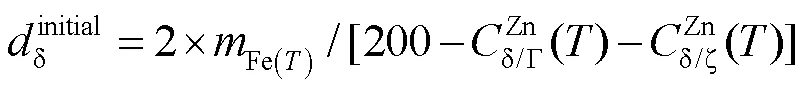
物相厚度起始值的设定:
1)合金化温度低于530 ℃时,η相转变为ζ相。η相厚度等于镀层厚度减去η相转变为ζ相的厚度,ζ相生长为式(15),设定其余两相的厚度等于0.01 μm。
2)合金化温度高于530 ℃时,η相转变为δ相。η相厚度等于镀层厚度减去η相转变为δ相的厚度,δ相生长公式为式(17),设定其余相的厚度等于0.01 μm。
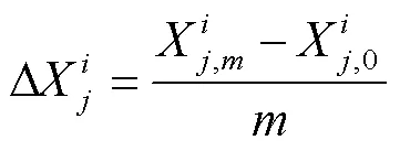
离散Fe-Zn相图不同相区物相,将物相等分成份(如图3所示),物相η-Zn、ζ、δ、Γ、α-Fe分别用1、2、3、4、5表示。
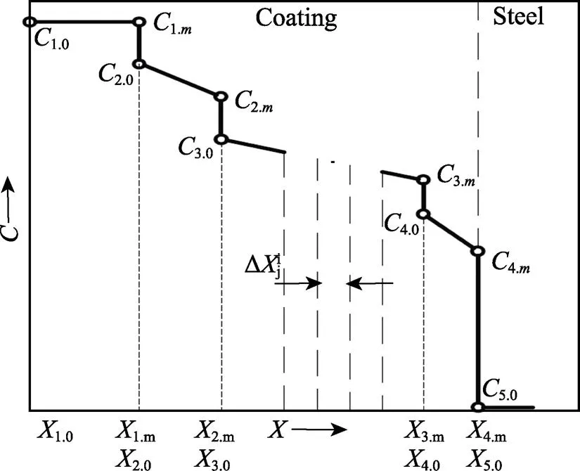
图3 镀层物相扩散区域离散示意图[27]
合金化模拟时,各物相界面随扩散时间不断移动,用式(20)表示距离步长[29]:

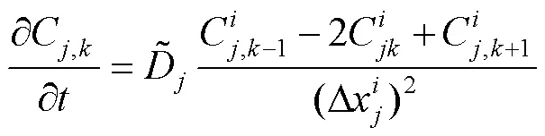
用菲克第二定律求解物相浓度:
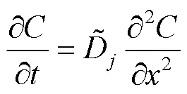
式中:为扩散元素的浓度;为扩散距离。

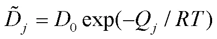
其中,气体常数值为8.314 J/(mol·K),物相扩散常数和扩散激活能见表1。
表1 物相扩散常数和扩散激活能[31]
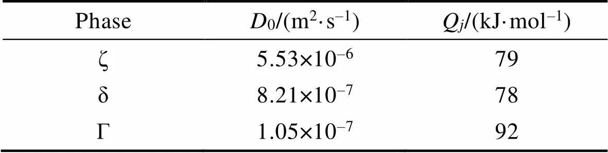
Tab.1 Phase diffusion constant and diffusion activation energy[31]
合金化模拟中,根据菲克第二定律,物相界面上积存质量等于流入质量减去流出质量。因此,物相界面移动速度由式(23)计算。

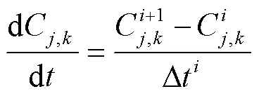
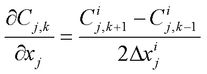
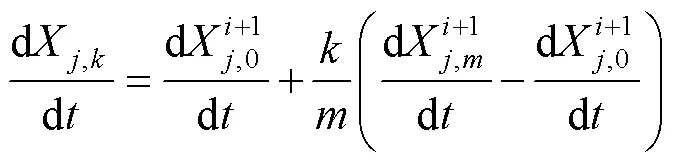
采用Murray-Landis可动网格公式(24)计算相图中离散点在不同时刻和位置的浓度值:

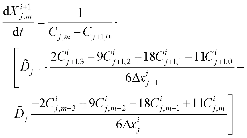
在界面(,)处,式(23)中界面移动速度用有限差分法转换为式(25)。
结合四点公式和有限差分法把式(23)转变 为(26):
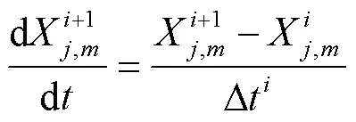
用前置差分方程表示公式(21)。
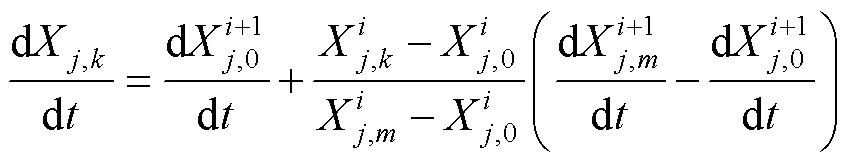
结合公式(20),将公式(30)转换为公式(31)。
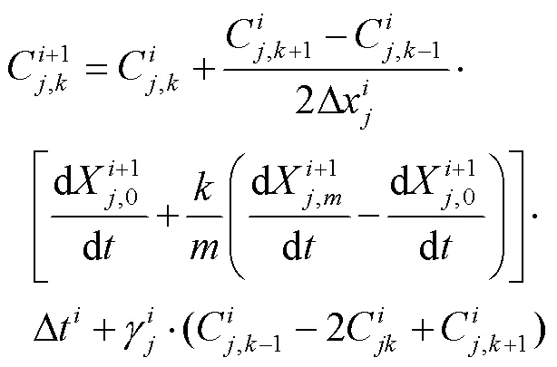
把公式(27)、(28)、(29)和(31)代入(24)中,计算(+1)时刻离散点的浓度值:
为保证模拟计算的收敛性,0满足:0≤0≤0.5。
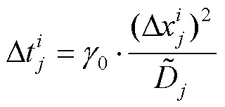
模型中采用最小的时间步长:
模拟结束后,求和模拟时间:
反复循环计算上面的模拟过程,达到设定合金化时间后,结束循环。
合金化模拟计算完成后,用式(37)计算镀层中铁含量。
3 镀层合金化模拟结果
模拟镀层合金化过程,实验材料选用无间隙原子钢(IF),钢的成分见表2。镀层中Al的质量分数为0.130%,镀层厚度为8 μm。模拟过程中,设定样品起始温度为350 ℃,感应加热分别升温到510 ℃和540 ℃,保温段分别在510 ℃和540 ℃保温相应时间。合金化工艺参数见表3。
实验设备采用自主搭建的分区控温多段式合金化设备,分为预热段、感应段和保温段3部分,在预热段,将样品加热到350 ℃;样品移动到感应段,快速升温到合金化温度510 ℃和540 ℃;进入保温段,分别在510 ℃和540 ℃保温一定时间,进行合金化处理。
表2 IF钢成分与含量

Tab.2 Composition and content of IF steel
表3 合金化工艺参数

Tab.3 Galvannealing process parameters
3.1 镀层物相生长过程模拟
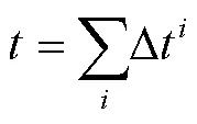
510 ℃合金化温度镀层物相生长过程的模拟结果如图4a所示,510 ℃时在相图相区的物相变化为η→ζ→δ→Γ。随合金化时间延长,η相逐渐被ζ相和δ相消耗,η相在8.2 s时被消耗完毕,η相消失后,ζ相也生长到镀层表面,并停止生长,然后δ相开始消耗剩余的ζ相快速生长到镀层表面,在9.7 s 时δ相停止生长,由于Γ相生长所需的合金化程度较高,Γ相通过消耗δ相缓慢生长。540 ℃合金化温度镀层物相生长过程的模拟结果如图4b所示,540 ℃时在相图相区的物相变化为η→δ→Γ,不会出现ζ相。镀层中η相直接转变为δ相,并在6.8 s消失,δ相生长到镀层表面时停止生长。随合金化时间的延长,镀层中Γ相通过消耗钢基板处的δ相生长。根据Arrhenius方程[30],合金化温度升高,镀层中原子的扩散系数也升高,Fe-Zn原子互扩散速率加快,因此合金化速率更快。相比510 ℃下Γ相的生长过程,540 ℃合金化温度模拟过程中Γ相生长速率更快。
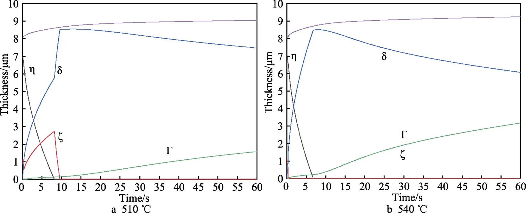
图4 镀层物相生长过程模拟
3.2 Fe含量模拟
合金化温度分别为510 ℃和540 ℃镀层Fe含量随时间变化如图5所示。随合金化温度的升高,相同时间下镀层的Fe含量更高。原因是温度升高,Fe-Zn原子扩散速率更快,合金化速率加快,合金化镀层Fe含量也更高。由Fe含量随时间的变化曲线可知,Fe含量在合金化前期增加速率较快,后期镀层Fe含量增加缓慢。由表1可知,物相扩散系数大小为ζ>δ>Γ。随合金化程度加深,镀层物相组成倾向于Fe含量更高的物相,合金化镀层物相扩散系数逐渐减小,Fe-Zn原子扩散速率降低,造成镀层Fe含量上升速率逐渐减慢。将实验测定Fe含量与模拟结果中Fe含量对比,两者Fe含量数值相近,模拟结果中Fe含量变化规律与实验相符,证明了模型的可信度。
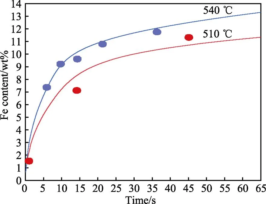
图5 Fe含量模拟与实验验证
3.3 镀层合金化过程物相分布模拟结果
为了更加直观地观察合金化过程中物相的生长过程,模拟不同保温时间下物相沿镀层截面的分布情况。合金化温度510 ℃分别保温0、3、8、15、30、45 s物相沿镀层截面分布如图6所示。在保温0 s时,镀层出现少量ζ相和δ相,主要由η相组成;保温3 s时,η相减少,转变为ζ相和δ相;保温8 s时,η相消失,镀层由ζ相和δ相组成;保温15 s时,ζ相消失,镀层主要由δ相组成;延长保温时间,Γ相缓慢生长。
合金化温度540 ℃分别保温0、3、8、15、30、45 s物相沿镀层截面分布如图7所示。保温0s时,η相少量转变为δ相;保温3s时,η相大量转变为δ相;保温8 s时,η相消失,镀层由δ相组成;随保温时间延长,Γ相通过消耗δ相生长。
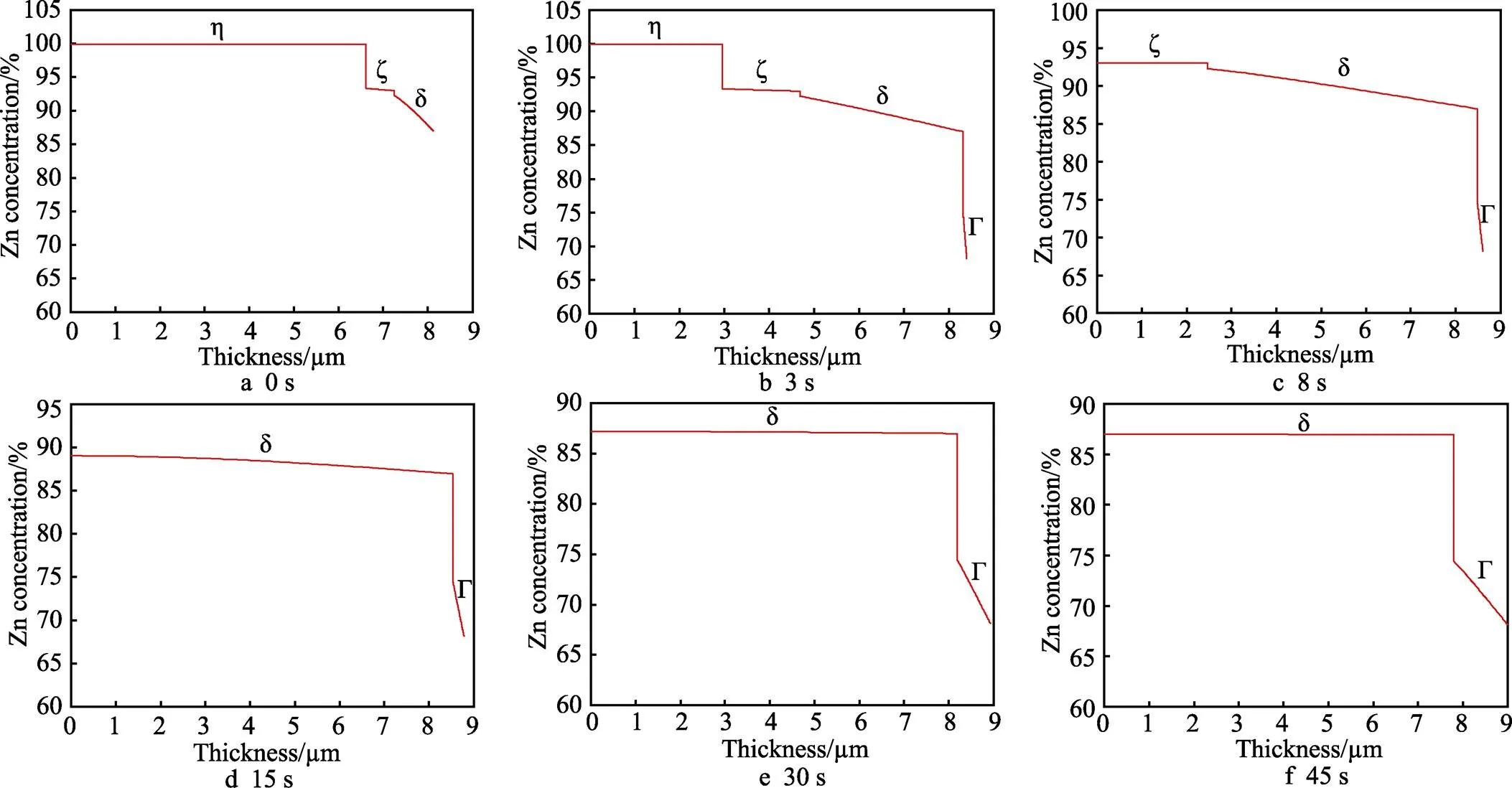
图6 510 ℃保温不同时间的物相沿镀层截面分布

图7 540 ℃保温不同时间的物相沿镀层截面分布
4 结论
1)模拟Fe-Zn相图不同相区温度镀层合金化过程,模拟510 ℃合金化温度物相转变为η→ζ→δ→Γ,540 ℃合金化温度物相转变为η→δ→Γ,模拟得到最佳镀层物相组成对应的合金化工艺:510 ℃保温9.7 s,540 ℃保温6.8 s。
2)研究得出合金化过程镀层Fe含量变化规律:在合金化前期Fe含量增加速率较快,随合金化程度提高,物相扩散系数降低,镀层Fe含量增加速率减慢。
[1] SHIBLI S M A, MEENA B N, REMYA R. A Review on Recent Approaches in the Field of Hot Dip Zinc Galvanizing Process[J]. Surface and Coatings Technology, 2015, 262: 210-215.
[2] CHAKRABORTY A, BHATTACHARJEE D, PAIS R, et al. Effect of Galvannealing Power on the Texture and Powdering Resistance of Industrially Produced Galvannealed Coating on Interstitial Free Steel[J]. Scripta Materialia, 2007, 57(8): 715-718.
[3] 徐秀清, 王顺兴. 连续热镀锌工艺进展与展望[J]. 表面技术, 2007, 36(1): 71-74. XU Xiu-qing, WANG Shun-xing. Development and Prospect of Continuous Hot-Dip Galvanized Process[J]. Surface Technology, 2007, 36(1): 71-74.
[4] INUI H, OKAMOTO N L, YAMAGUCHI S. Crystal Structures and Mechanical Properties of Fe-Zn Intermetallic Compounds Formed in the Coating Layer of Galvannealed Steels[J]. ISIJ International, 2018, 58(9): 1550-1561.
[5] YU Xue-bin, LI Mang-mang. Research on the Lack of Alloying in the Galvannealed Coating of Automotive Sheet Steel[J]. Baosteel Technical Research, 2008, 2(4): 17-20.
[6] PARK H, JEONG Y J, LEE K, et al. Effect of Galvannealing Temperature on Coating Microstructure Evolution Correlated to Flaking Degradation on Galvannealed Interstitial-Free Steel[J]. Surface and Coatings Technology, 2020, 404: 126446.
[7] Mataigne J M, Drillet P, Pra J M, et al. Optimized Galvannealed Coatings Microstructure for Automotive Applications[C]// 3rd in Conf on Zinc and Zinc Alloy Coated Steel Sheet. Chicago: Iron and Steel Society, 1995.
[8] ZHONG W, NG H F, ICHIKAWA M. Effect of Coating Characteristics on Powdering Performance of Galvanneal Coatings[C]// The 4th International Conference on Zinc and Zinc Alloy Coated Steel Sheet. Makuhari: Iron and Steel Institute of Japan, 1998.
[9] MASSALSKI T B. Binary alloy phase diagrams[M]. 2nd ed. Materials Park, Ohio: ASM International, 1990.
[10] BELIN R, TILLARD M, MONCONDUIT L. Redetermination of the Iron-Zinc Phase FeZn13[J]. Acta Crystallographica Section C Crystal Structure Communications, 2000, 56(3): 267-268.
[11] HONG M H, SAKA H. Transmission Electron Microscopy of the Iron-Zinc1Intermetallic Phase[J]. Scripta Materialia, 1997, 36(12): 1423-1429.
[12] KAINUMA R, ISHIDA K. Microstructural Evolution of Intermetallic Compound Layers Formed in Fe/Zn Binary Diffusion Couples[J]. Tetsu-to-Hagane, 2005, 91(3): 349- 355.
[13] KAINUMA R, ISHIDA K. Reactive Diffusion between Solid Fe and Liquid Zn at 723 K[J]. ISIJ International, 2007, 47(5): 740-744.
[14] OKAMOTO N L, TANAKA K, YASUHARA A, et al. Structure Refinement of the Δ1p Phase in the Fe-Zn System by Single-Crystal X-Ray Diffraction Combined with Scanning Transmission Electron Microscopy[J]. Acta Crystallographica Section B, Structural Science, Crystal Engineering and Materials, 2014, 70(Pt 2): 275-282.
[15] HAN K, OHNUMA I, OKUDA K, et al. Experimental Determination of Phase Diagram in the Zn-Fe Binary System[J]. Journal of Alloys and Compounds, 2018, 737: 490-504.
[16] OKAMOTO N L, INOMOTO M, TAKEBAYASHI H, et al. Crystal Structure Refinement of the Γ- and Γ1-Phase Compounds in the Fe-Zn System and Orientation Relationships among Α-Fe, Γ and Γ1 Phases in the Coating Layer of Galvannealed Steel[J]. Journal of Alloys and Compounds, 2018, 732: 52-63.
[17] KANAPA L, BOONYONGMANEERAT Y, SUPRADIST M. Finite Difference Kinetics Modeling for Galvanized Steels with Post Heat Treatments[J]. Advanced Materials Research, 2014, 1025-1026: 723-730.
[18] GAO Hai-yun, LI Xiao-bo, FENG Wen-ying, et al. Numerical Modeling of Zinc Diffusion during Sherardizing Process[J]. Journal of Phase Equilibria and Diffusion, 2018, 39(2): 237-245.
[19] VERMA A K, CHANDRA S, BANDYOPADHYAY N, et al. Optimization of Galvannealing Parameters through Numerical Modeling of Galvannealing Process[J]. Metallurgical and Materials Transactions A, 2009, 40(5): 1153- 1159.
[20] KANAMARU T, NAKAYAMA M. Alloying Reaction Control in Production of Galvannealed Steel[J]. Journal of the Society of Materials Science, Japan, 1995, 44(504): 150-156.
[21] 苏旭平, 李智, 尹付成, 等. 热浸镀中硅反应性研究[J]. 金属学报, 2008, 44(6): 718-722. SU Xu-ping, LI Zhi, YIN Fu-cheng, et al. A Study of the Silicon Reactivity in Galvanizing[J]. Acta Metallurgica Sinica, 2008, 44(6): 718-722.
[22] JORDAN C E, MARDER A R. Fe-Zn Phase Formation in Interstitial-Free Steels Hot-Dip Galvanized at 450℃: Part II 0.20wt% Al-Zn Baths[J]. Journal of Materials Science, 1997, 32(21): 5603-5610.
[23] KOBAYASHI S. Effects of Si Solid Solution in Fe Substrate on the Alloying Reaction between Fe Substrate and Liquid Zn[J]. Tetsu-to-Hagane, 2017, 103(7): 429- 433.
[24] MIYATA M, FUSHIWAKI Y, SUZUKI Y, et al. Effect of Si/Mn Ratio on Galvannealing Behavior of Si-Added Steel[J]. ISIJ International, 2018, 58(9): 1600-1607.
[25] HERTVELDT I, DE COOMAN B C, CLAESSENS S. Influence of Annealing Conditions on the Galvanizability and Galvannealing Properties of TiNb Interstitial-Free Steels, Strengthened with Phosphorous and Manganese[J]. Metallurgical and Materials Transactions A, 2000, 31(4): 1225-1232.
[26] MARDER A R. The Metallurgy of Zinc-Coated Steel[J]. Progress in Materials Science, 2000, 45(3): 191-271.
[27] SU Xu-ping, XU Peng, LIU Ya, et al. Mathematical Modeling and Numerical Simulation of Layer Growth and Phase Transformation during Galvannealing Process[J]. Surface and Coatings Technology, 2012, 206(23): 5012- 5021.
[28] ONISHI M, WAKAMATSU Y, MIURA H. Formation and Growth Kinetics of Intermediate Phases in Fe-Zn Diffusion Couples[J]. Transactions of the Japan Institute of Metals, 1974, 15(5): 331-337.
[29] TSUJI S. Numerical Modeling of Multiphase Diffusion in the Process of Homogenizing in Binary Alloys[J]. Metallurgical and Materials Transactions A, 2001, 32(3): 681- 690.
[30] 胡赓祥, 蔡珣, 戎咏华. 材料科学基础[M]. 3版. 上海: 上海交通大学出版社, 2010. HU Geng-xiang, CAI Xun, RONG Yong-hua. Fundamentals of Materials Science[M]. 3rd ed. Shanghai: Shanghai Jiao Tong University Press, 2010.
[31] 徐鹏. 合金化热镀锌镀层组织模拟及应用[D]. 湘潭: 湘潭大学, 2012. XU Peng. Microstructure Simulation and Application of Alloying Hot Dip Galvanized Coating[D]. Xiangtan: Xiangtan University, 2012.
Simulation of the Growth Process of Galvannealed Coatings at Different Zone Temperature in Fe-Zn Phase Diagram
1,2,1,1*,1
(1. a. School of Material Science and Engineering, b. State Key Laboratory of Advanced Special Steel, Shanghai University, Shanghai 200444, China; 2. Baosteel Zhanjiang Iron & Steel Co., Ltd., Guangdong Zhanjiang 524033, China)
Galvannealed steel (GA) is widely used in the automotive industry, household appliances and construction for its good weldability, paintability, corrosion resistance and heat resistance. However, compared to GI coatings, GA coatings often fail in the press forming because the brittle and high hardness Fe-Zn phases can easily cause coating to undergo powdering and flaking, which results in severe decrease of its corrosion resistance and quality. Therefore, in order to improve the formability of GA coatings, the work aims to establish a GA coating phases growth model to control the coating phase composition, and obtain the best galvannealing process parameters to guide production. Based on the latest Fe-Zn phase diagram, the phase zone boundary concentration equation was formulated and combined with the phase zone boundary concentration equation, the phase boundary movement equation and the phase growth equation, GA coating phase growth model was constructed. The galvannealing model was constructed to simulate the growth process of phases η, ζ, δ and Γ in different phase zones of GA coating, the distribution of the phases along GA coating cross-section, and the change of GA coating Fe content during the galvannealing process. The established model could successfully simulate the phase growth process in different phase zones of the Fe-Zn phase diagram, and compare the growth differences of different phases in different phase zones. The phase transformation below the galvannealing temperature of 530℃ was η→ζ→δ→Γ, while the phase transformation above the galvannealing temperature of 530 ℃ was η→δ→Γ. The galvannealing temperature was set at 510 ℃ and 540 ℃. According to the simulation results at 510 ℃, η phase was gradually consumed by ζ phase and δ phase, and disappeared at 8.2 s. At the same time, ζ phase also grew to the surface of coating and stopped growing. Then the δ phase consumed the remaining ζ phase and grew rapidly to the coating surface at 9.7 s, Γ phase grew slowly by consuming δ phase and the thickness of Γ phase reached 1μm at 38 s. Simulation results at 540 ℃ indicated that η phase directly transformed to δ phase and disappeared at 6.8 s. δ phase stopped growing when reaching the surface of the coating at 6.8 s. With the extension of galvannealing time, Γ phase grew slowly by consuming δ phase from the steel substrate and the thickness of Γ phase reached 1 μm at 17 s. The galvannealing process to obtain the best coating phases was simulated: 510 ℃ for 9.7 s and 540 ℃ for 6.8 s. The study shows that the change rule of Fe content in GA coating during the galvannealing process is that the increase rate of Fe content is faster at the initial stage of galvannealing, and the increase rate of Fe content slows down with the increase of galvannealing degree, because the phase diffusion coefficient of Fe-Zn phase diagram is ζ>δ>Γ. Therefore, as galvannealing time goes on, phases with high Fe content in GA coating increase, GA coating phase diffusion coefficient decreases with the increase of Fe content and the diffusion rate of Fe-Zn atoms decreases. GA coating phases growth model can simulate the best process parameters at different galvannealing temperature, and provide a process reference for the production of GA coatings.
galvannealed steel; high strength steel; mathematical model; galvannealing process; Fe-Zn alloy
2022-08-30;
2023-02-08
TG335.22
A
1001-3660(2023)10-0403-08
10.16490/j.cnki.issn.1001-3660.2023.10.036
2022-08-30;
2023-02-08
上海市自然基金(21ZR1423600);中央引导地方项目(216Z1004G)
Shanghai Natural Fund (21ZR1423600); Central Guidance Local Project (216Z1004G)
刘诗文, 孟宪陆, 赵彦, 等. Fe-Zn相图不同相区温度合金化锌镀层生长过程模拟[J]. 表面技术, 2023, 52(10): 403-410.
LIU Shi-wen, MENG Xian-lu, ZHAO Yan, et al. Simulation of the Growth Process of Galvannealed Coatings at Different Zone Temperature in Fe-Zn Phase Diagram[J]. Surface Technology, 2023, 52(10): 403-410.
通信作者(Corresponding author)
责任编辑:刘世忠
