Design and Structure Optimization of Plenum Chamber with Airfoil Baffle to Improve Its Outlet Velocity Uniformity in Heat Setting Machines
2023-10-29QIANMiaoWEIPengli魏鹏郦LINZijie林子杰XIANGZhongHUXudong胡旭东
QIAN Miao(钱 淼), WEI Pengli(魏鹏郦), LIN Zijie(林子杰), XIANG Zhong(向 忠), HU Xudong(胡旭东)
Zhejiang Provincial Key Lab of Modern Textile Machinery, School of Mechanical Engineering, Zhejiang Sci-Tech University, Hangzhou 310018, China
Abstract:The plenum chamber of a heat setting machine is a key structure for distributing hot air to different air channels. Its outlet velocity uniformity directly determines the heating uniformity of textiles, significantly affecting the heat setting performance. In a traditional heat setting machine, the outlet airflow maldistribution of the plenum chamber still exists. In this study, a novel plenum chamber with an airfoil baffle was established to improve the uniformity of the velocity distribution at the outlet in a heat setting machine. The structural influence of the plenum chamber on the velocity distribution was investigated using a computational fluid dynamics program. It was found that a chamber with a smaller outlet partition thickness had a better outlet velocity uniformity. The structural optimization of the plenum chamber was conducted using the particle swarm optimization algorithm. The outlet partition thickness, the transverse distance and the longitudinal distance of the optimized plenum chamber were 20, 686.2 and 274.6 mm, respectively. Experiments were carried out. The experimental and simulated results showed that the optimized plenum chamber with an airfoil baffle could improve the outlet velocity uniformity. The air outlet velocity uniformity index of the optimized plenum chamber with an airfoil baffle was 4.75% higher than that of the plenum chamber without an airfoil baffle and 5.98% higher than that of the conventional chamber with a square baffle in a commercial heat setting machine.
Key words:velocity distribution uniformity; structure optimization; numerical simulation; airfoil; plenum chamber; heat setting
0 Introduction
The heat setting machine is widely used in the textile industry, which is the key equipment to ensure the dimensional accuracy and the geometric stability of fabrics and directly affects the quality of textiles[1-5]. A typical heat setting machine consists of 8-12 drying rooms with plenum chambers and air ducts. The high-temperature air generated by the cycle blower and the heat exchanger flows into the plenum chamber and air ducts for flow distribution and then blows onto the fabric to dry the wet fabric[6-7]. Usually, in a drying room, more than ten air ducts are connected to a plenum chamber, and there are dozens of nuzzles on an air duct[8]. Owing of the complex flow passage, flow maldistribution among different nozzle outlets always exists, leading to uneven drying and inadequate heat setting, affecting the efficient and high-quality production of fabrics[9]. Therefore, it is essential to design the structure and optimize the flow passage of the drying room in a heat setting machine for flow distribution uniformity[10].
So far, there have been a series of studies on the optimization of flow passage for flow distribution uniformity[11-16]. Some studies focus on the optimization of the runner structure and size based on different optimization algorithms[17-18]. Gaoetal.[19]adopted a genetic algorithm and computational fluid dynamics(CFD) to design and optimize the runner shape and size for an even flow distribution. Zhangetal.[15]studied the structural effects on flow uniformity in dividing manifold systems. It was found that the area ratio had an important effect on flow uniformity. Novel flow passage configurations have been proposed for flow distribution uniformity[20-21]. Caoetal.[21]proposed a novel bifurcating flow distributor and discussed the effects of the bifurcation angle on flow distribution performance.
The flow distribution can also be controlled by adding baffles to the channel[22-25]. Xieetal.[22]added two baffles into the flow passage, and the numerical simulation results indicated that the baffles could increase flow uniformity. Weietal.[26]designed a baffle and arranged it at the inlet of a fluid distributor. Structural optimization of the baffle was carried out via numerical simulation, and a smaller fluid maldistribution factor was obtained with the optimized baffle. Kitayamaetal.[24]have optimized the baffle structure by sequential approximate optimization, and the results showed that the flow maldistribution was reduced by 34% by using the optimized baffle in the flow passage of heat exchangers. The above researches show that the addition of baffles can improve the uniformity of flow. However, the baffle structures in the above researches are not suitable for balancing the airflow distribution between the inlets of the plenum chamber.
Previous studies have mainly focused on the heat and mass transfer of textiles during the heat setting process for energy conservation and consumption reduction[27-28], and there are few reports on fluid field analysis and structural optimization of plenum chambers and air ducts. Although the structural effects of the air ducts on the flow uniformity are investigated, and the structure of the plenum chamber is optimized in several studies[9-10,29], the flow maldistribution at the outlet of the plenum chambers in the heat setting machine still exists, which needs to be further improved.
At present, to improve the uniformity of the outlet velocity distribution, most companies that make heat setting machines use square deflectors in the static pressure box. It is found that the outlet velocity distribution is uneven. However, the airfoil deflector might be more effective than the square deflector in diverting and guiding the flows. Since the airfoil baffle has the better merit to direct fluid flow[30]mentioned above, in this paper, the airfoil structure is introduced into the design of the plenum chamber, and a novel plenum chamber with an airfoil baffle is developed.
Firstly, an airflow field simulation is carried out using CFD, and the structural influence of the plenum chamber on the velocity distribution at the outlet is studied using the central composite design method. Secondly, the relationship between the outlet velocity distribution and the structural parameters of the plenum chamber is established, and a better plenum chamber is obtained using the particle swarm optimization(PSO) algorithm. Thirdly, comparisons of the outlet velocity uniformity between the proposed plenum chamber and conventional chambers are conducted. Finally, experiments are conducted to evaluate the theoretical results and demonstrate that the addition of an airfoil structure can improve the velocity distribution uniformity.
1 Physical and Mathematical Modelling
1.1 Geometrical model
A geometrical model of the plenum chamber with an airfoil baffle was developed, and the influence of the structure on the outlet velocity uniformity was studied. The geometrical model of the plenum chamber consisted of a collector, an impeller, and a chamber, as shown in Fig.1(a). To increase the calculation accuracy of the outlet velocity, a rectangular external airflow field was added next to the plenum chamber outlet. The external air passed through the collector into the plenum chamber because of the rotation of the impeller, and was injected into the external airflow field through the plenum chamber outlet.
An airfoil baffle (NACA M27 AIRFOIL) was added to the middle of the chamber to control the airflow field. The structural parameters are shown in Fig.1(b). The outlet of the plenum chamber was equipped with 12 outlet partitions to separate the outlet into 12 small air outlets that connected the 12 air ducts. A 2D schematic diagram is shown in Fig.1(b), whereDis the thickness of the outlet partition;TandLare the transverse and longitudinal distances between the airfoil baffle and the impeller center, respectively.
1.2 Governing equations
Because the velocity of the fluid was less than 0.3Ma, it is assumed that the fluid airflow inside the plenum chamber is in a steady-state, turbulent airflow, and incompressible state for simplification.
The continuity equation is
(1)
whereρis the fluid density;uiis the velocity component alongX,YandZ;xiis the coordinate ofX,YandZ.
The conservation of the momentum equation is
(2)
wherePis the static pressure of the fluid;τijis the stress tensor;ρgiis the body force caused by gravity along theidirection.
The equation ofkis
(3)
wherekis the turbulent kinetic energy.
The equation ofεis
(4)
with
(5)
(6)
(7)
(8)
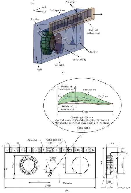
Fig.1 Plenum chamber with airfoil baffle: (a) geometric model; (b) 2D structural schematic diagram(unit:mm)
whereεis the turbulence energy dissipation rate;μis the fluid viscosity;μtis the turbulent viscosity;Gkis the generation of turbulent kinetic energy of the average velocity gradient.
1.3 Boundary conditions
The multi-reference frame (MRF) method, commonly used for the airflow field analysis of fans, was chosen to simulate the rotation of the impeller in the plenum chamber. Because it is a steady-state model, the computational efficiency can increase significantly without affecting the calculation precision. In the plenum chamber, only the impeller zone was set to rotate together with the wall surface, and its rotation speed was 720 r/min. The working fluid air velocity of 4.5 m/s was specified as the inlet condition (Fig.1(a)). A gauge pressure of zero was set as the outlet condition, and all the other surfaces were set as walls.
1.4 Calculation methods
The differential equations were solved using ANSYS FLUNET 19.2. The pressure-velocity coupling scheme was set as the coupled scheme. The equations of the momentum, the turbulent kinetic energy, and the turbulent dissipation rate were discretized using a second-order upstream scheme.
To study the effect of the grid number on the numerical results, the grid independence was first examined. In this paper, six grid configurations with numbers of 1.8×10⁵, 1.0×10⁶, 1.8×10⁶, 2.6×10⁶, 3.4×10⁶, and 4.5×10⁶were used to verify the grid independence. The average velocities at the outlet of the plenum chamber for different grid numbers are listed in Table 1. It was found that the change in the average velocity was within 3% when the grid number was greater than 2.6×10⁶. Considering the calculation accuracy and the performance of the computer, a grid number of 2.6×10⁶was chosen for the numerical simulation.
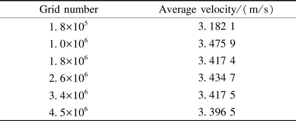
Table 1 Average velocities of chamber outlet with different grid numbers
2 Results and Discussion
2.1 Effect of geometrical parameters
To optimize the structure of the plenum chamber proposed in this study, the effects ofD,T, andLon the velocity distribution uniformity at the outlet of the plenum chamber were first studied. Considering the structural limitations of the plenum chamber, the changing ranges of the three parameters were set, as shown in Table 2.
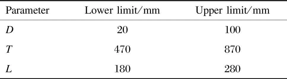
Table 2 Range of central composite design parameters
In this study, the values of the plenum chamber structural parameters were obtained by using the central composite design method to comprehensively analyze the effect ofD,TandL. The data analysis software JMP was used based on Table 2, and 16 groups of structural parameters were obtained as shown in Table 3. The geometrical models of the plenum chamber were adjusted according to the parameters listed in Table 3, and a related numerical simulation was performed to study the outlet velocity uniformity.
For quantitative analysis of the airflow distribution uniformity at the outlet of the plenum chamber, the total velocity uniformity indexUItwas used:
(9)

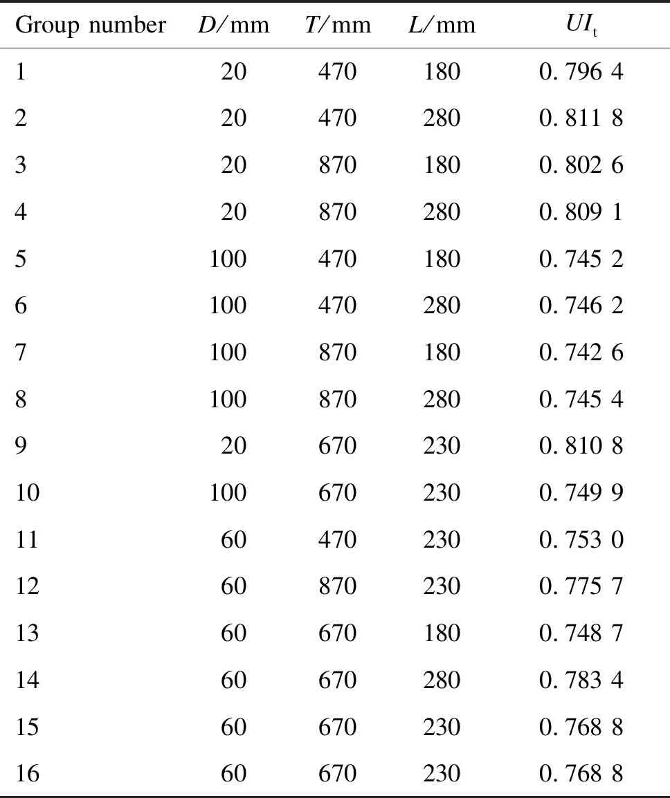
Table 3 Structural parameters obtained by center composite design method
2.1.1Effectofoutletpartitionthickness
Figure 2 shows the velocity contours at the outlet of the plenum chamber with different outlet partition thicknesses (D=20, 60, 100 mm). From Fig.2, it can be observed that the velocity difference in a single air outlet increases with an increase inD. This is because, with an increase in the outlet partition thickness in the chamber, the airflow generated by the impeller rotation is introduced into each air outlet by the partition before it spreads sufficiently, resulting in a large difference in velocity in a single air outlet.
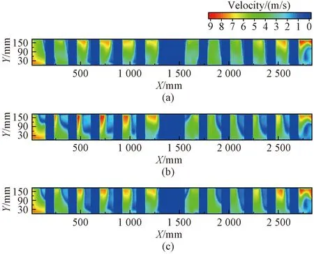
Fig.2 Velocity contours with different outlet partition thicknesses: (a)Group 9 ; (b)Group 10; (c)Group 15
From Table 3, the velocity uniformity index for Group 9 is larger than that for Groups 10 and 15, indicating that the plenum chamber with the airfoil structure for Group 9 has a better outflow distribution performance.
2.1.2Effectoftransversedistance
The calculated velocity distributions with various transverse distances under the condition thatDandLare 20 mm and 280 mm, respectively, are shown in Fig.3. When the airfoil baffle was close to the impeller (T= 470 mm), more gas was directed to the left side of the plenum chamber along the left side of the airfoil, so the airflow was mainly concentrated in Nos. 1-6 air outlets (Fig.3) where a high-velocity region appeared. WhenTincreased to 870 mm, the gas on the right side of the chamber increased, and thus the velocity on the left side decreased. When the deflector was close to the impeller, the airflow velocity of the left air outlets (Nos. 1-6 air outlets) was significantly higher than that of the right air outlets (Nos. 7-12 air outlets). This is because the deflector is too close to the left impeller, resulting in a relatively closed environment on the left side of the static pressure box, so that the airflow is concentrated at Nos. 1-6 air outlets.
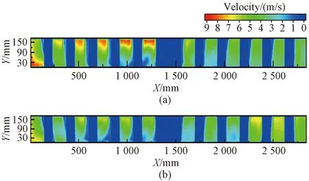
Fig.3 Velocity contours with different transverse distances: (a) Group 2; (b) Group 4
To further analyze the velocity distribution uniformity among 12 air outlets, the velocity of each air outlet was calculated as shown in Fig.4. The air outlet velocities on the left side (Nos. 1-6) were larger than those on the right side (Nos. 7-12) when the airfoil baffle was located near the impeller position. Similarly, an adverse phenomenon was observed when the airfoil baffle was located away from the impeller (T=870 mm). However, as shown in Fig.4, the velocities on the right side increased significantly when the airfoil baffle was far from the impeller, which was also harmful to the velocity distribution uniformity.
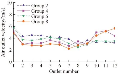
Fig.4 Velocities of 12 air outlets
2.1.3Effectoflongitudinaldistance
The calculated velocity distributions with various longitudinal distancesLfor Groups 13, 14, and 15, are shown in Fig.5.

Fig.5 Velocity contours with different longitudinal distances: (a) Group 13; (b) Group 14; (c) Group 15
AsLincreased, the airfoil baffle was closer to the bottom of the plenum chamber, and the airflow generated by the impeller was better distributed. The airflow passing along the upper surface of the airfoil baffle to the middle air outlets increased, and that moving along the lower surface to the right air outlets was reduced, thereby improving the airflow distribution uniformity at the outlets of the plenum chamber. The airfoil baffle then guides the fluid more obviously, thereby improving airflow maldistribution. Therefore, it can be observed from Fig.5 that the airflow distribution is evener whenL= 280 mm. The same demonstration was also obtained by calculating the total velocity uniformity indices for Groups 13, 14, and 15, as shown in Table 3.
Based on the velocity contours and the total velocity uniformity index in Table 3, it can be concluded that when the airfoil deflector from the impeller has a transverse distance of 670 mm and a longitudinal distance of 280 mm, the plenum chamber outlet can obtain a better uniformity of the airflow field.
2.2 PSO optimization
2.2.1Modellingfitting
To further optimize the airflow field, the relationship among the total velocity uniformity indexUItand the structural parametersT,LandDwas fitted using the standard least-squares method based on the data in Table 3. The formula is defined as
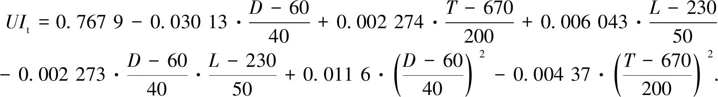
(10)
The fitting accuracy was evaluated in this study. Table 4 lists the coefficients ofR2and adjustedR2. For a fitting model, largeR2and adjustedR2values close to 1 correspond to high accuracy of the model. From Table 4, the values ofR2and adjustedR2are 0.946 2 and 0.910 4, respectively. These values are close to 1, demonstrating that the values predicted by the fitting model agree well with the simulation results shown in Table 3. In this study, the model was used to optimize the structural parameters of the plenum chamber.
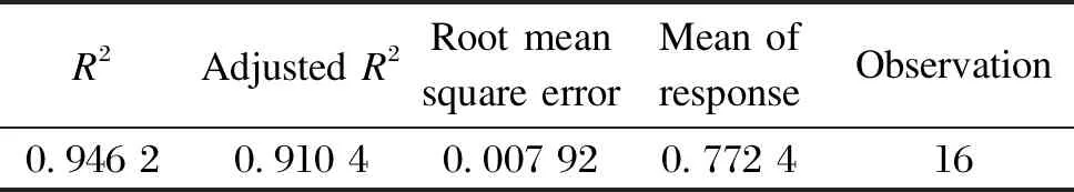
Table 4 Summary of fit
2.2.2Optimizationcalculation
The PSO was chosen to optimize the structural parameters of the plenum chamber. Considering the production process and installation of the plenum chamber, the size constraints ofT,LandDwere set as
20≤D≤100,
(11)
470≤T≤870,
(12)
180≤L≤280,
(13)
(14)
2.2.3Optimizationresults
The maximum total velocity uniformity indexUItof 0.817 is obtained based on the PSO algorithm mentioned above whenD,T, andLare 20, 686.2 and 274.6 mm, The airflow field of the plenum chamber was simulated using these structural parameters, and the outlet velocity uniformity was compared with that of a plenum chamber without an airflow baffle, as shown in Fig.6. The air outlet velocities of the plenum chamber without an airflow baffle were higher on both sides and lower in the middle. By adding an airfoil baffle, the lower airflow in the plenum chamber was better separated by the airflow baffle. Part of the airflow was directed to the middle air outlets, which increased the air velocity from outlets Nos. 6 - 8. Because of the airfoil baffle, the airflow decreases, and the airflow distance between the right air outlets and the impeller increases, causing the airflow to spread sufficiently. The existence of the airfoil baffle makes the velocity of Nos. 10-12 air outlets more evenly distributed, and the velocity uniformity of the plenum chamber is improved.
The total velocity uniformity index obtained via the numerical simulation was 0.816 7. The difference between this value and the predicted value of 0.817 2 obtained from the fitting model was small, further verifying the accuracy of the fitting model.
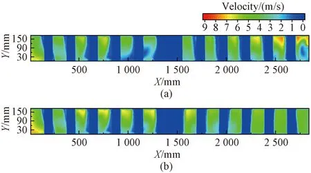
Fig.6 Velocity contours at outlet of plenum chamber: (a) no baffle (D=20 mm) ; (b) with airfoil baffle (D=20 mm, T=686.2 mm, L=274.6 mm)
The velocity of each air outlet was calculated, and an air outlet uniformity indexUIewas developed to evaluate the velocity distribution maldistribution among 12 air outlets. The formula forUIeis
(15)

The air outlet uniformity indices in the two types of plenum chambers were obtained through simulations. For the plenum chamber without a baffle,UItandUIewere 0.783 4 and 0.919 9, respectively, whereas for the plenum chamber with an airfoil baffle,UItandUIewere 0.816 7 and 0.947 5, respectively. Compared with the plenum chamber without a baffle, itsUItincreased by 4.25%, and itsUIeincreased by 3.00%, indicating that the plenum chamber with an airfoil baffle had better air outlet performance.
3 Experimental Validation
3.1 Experimental setup
Experiments were conducted to verify the reliability of the theoretical results. Figure 7 shows a schematic of the experimental system for the outlet velocity measurement of the plenum chamber. The experimental system mainly consisted of a plenum chamber, anX-Ymoving platform, an anemometer, and a microcontroller. The anemometer was a hot-wire anemometer (Model RS-FS-V05-9TH), with a measuring range of 0 to 30 m/s and a precision of ±(0.2+2% FS) m/s. TheX-Ymoving platform included a horizontal displacement mechanism and a vertical displacement mechanism, whose stepper motors were controlled by the microcontroller MEGA2560 programmed by Arduino. The air outlet velocity was measured using an anemometer installed on the horizontal displacement mechanism, and then transferred to a computer.
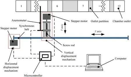
Fig.7 Schematic diagram of experimental platform
3.2 Experimental procedure
In this study, three types of plenum chambers were used to verify the merits of the optimized plenum chamber. These were a chamber without a baffle, a chamber with an airfoil baffle, and a chamber with a conventional square baffle. The structures and the sizes of three chambers were identical, except for the set of baffles. The structural size of the chamber with a conventional square baffle was obtained from a commercial heat setting machine widely used in the market. The length, the width, the transverse distance, and the longitudinal distance were 250, 115, 670, and 230 mm, respectively. Before the measurement, the rotation speed of the fan in the chamber was 720 r/min. During the measurement process, the anemometer was moved along vertical and horizontal directions and driven by theX-Ymovement platform to measure the air outlet velocity of the plenum chamber. The step size is controlled by a microcontroller. The velocities of 5 032 points at the outlet of the plenum chamber were measured. A total of 296 points were in the horizontal direction with an interval of 9.5 mm, and 17 points were in the vertical direction with an interval of 10.0 mm. The anemometer was stayed for 4 s at every point to guarantee the measurement stability and enhance the measurement accuracy of the velocity. After the measurement, the velocity of each point was transmitted to the microcontroller and the computer used for data reduction.
3.3 Comparison between experimental results and simulated ones
The variation in the velocity of each air outlet for two types of plenum chambers is shown in Fig.8. The outlet velocity distribution uniformity obtained via experiments for the chamber without a baffle was compared with that obtained via simulation (Fig.8(a)). Under the condition of a fan speed of 720 r/min, the measured inlet velocity was just 3.5 m/s for the plenum chamber without a baffle; therefore, the inlet velocity was 3.5 m/s for the simulation. It can be observed that the difference between the experimental and the simulated results is small, and the distribution law of the air outlet velocities from the experiments is consistent with the simulation. The air outlet velocities of the plenum chamber without the baffle were higher on both sides of the chamber outlet. Figure 8(b) shows a comparison of the experiment with the simulation for a chamber with an airfoil baffle. Both the simulated and the experimental results show that the air velocities in the middle of the chamber outlet increase by adding an airfoil baffle into the plenum chamber.
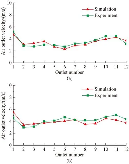
Fig.8 Velocity of each air outlet obtain from simulation and experiment: (a) no baffle; (b) airfoil baffle
3.4 Comparison among three types of plenum chambers
Three types of plenum chambers were used to verify the merits of the optimized plenum chamber with an airfoil baffle. These were a contrast among a chamber with no baffle, a chamber with an airfoil baffle, and a chamber with a traditional square baffle. The air outlet velocities were measured in these three chambers experimentally. Figure 9 shows the velocity distribution contours for the three types of plenum chambers. As shown in Fig.9, at the same fan speed of 720 r/min, the total outlet velocity of the plenum chamber with a baffle was larger than that without a baffle. This is because the addition of a baffle into the chamber can create a negative pressure near the impeller, thereby increasing the inlet airflow rate of the chamber.
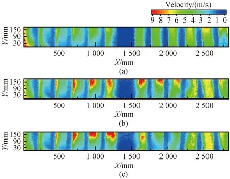
Fig.9 Velocity distribution contours obtained via experiments for three types of plenum chambers: (a) no baffle; (b) airfoil baffle; (c) square baffle
In the plenum chamber without a baffle, air is more likely to flow sideways; therefore, the velocities at both sides of the outlet are larger than those in the middle, resulting in airflow maldistribution, which is consistent with the simulation. By adding a square baffle, the velocities in the middle of the outlet increase, as shown in Figs.9 and 10. However, the airflow was directed to the upward side of No. 6 air outlet along the side of the square baffle, resulting in a large velocity difference along the height of No. 6 air outlet, as shown in Fig.10. Therefore, the air outlet velocity is larger near the upper wall and smaller near the lower wall at No. 6 air outlet. In the plenum chamber, more airflow is directed to air outlets Nos. 5 and 6 along the side of the square baffle, reducing the airflow into air outlets Nos. 8 and 9. Thus, it can be observed from Fig.9 that the velocity maldistribution at the outlet of the plenum chamber is obvious.
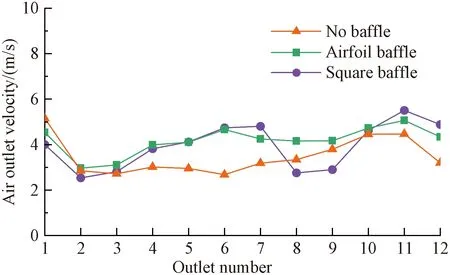
Fig.10 Velocity of each air outlet obtained via experiments for three types of plenum chambers
An optimized plenum chamber with an airfoil baffle can improve airflow distribution. The airfoil baffle can separate the airflow below the impeller so that part of the airflow moves to the middle area of the plenum chamber with the airfoil baffle, increasing the airflow rate of tuyeres 6-8. At the same time, it reduces the airflow moving to the right area, making the airflow fields of tuyeres 10 - 11 on the right more evenly distributed so as to achieve the role of airflow diversion.
The experimental values ofUIefor three types of plenum chambers were calculated. The results are listed in Table 5. It can be seen thatUIeof the plenum chamber with the airfoil baffle was 4.75% higher than that without a baffle and 5.98% higher than that with a conventional square baffle. The experimental results show that the optimized plenum chamber with an airfoil baffle exhibites a better airflow performance at the outlet.
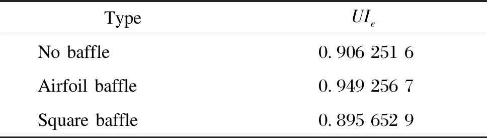
Table 5 UIe for three types of plenum chambers
4 Conclusions
In this study, a novel plenum chamber with an airfoil baffle was developed to improve the airflow distribution performance at the outlet of the plenum chamber. The airflow field was investigated via a numerical simulation. The effects of the structural parameters on the velocity distribution uniformity were discussed using the central composite design method, and the plenum chamber was optimized using the PSO algorithm. The main conclusions are as follows.
1) Through the analysis of 16 groups of simulation results, the influence of the thickness of the outlet partition and the position of the airfoil baffle on the outlet velocity uniformity of the plenum chamber was investigated. It was found that a chamber with a smaller outlet partition thickness, such as 20 mm, had a better outlet velocity uniformity. Comparing the airfoil baffles at different positions, it was found that when the transverse distance between the baffle and the impeller center was 670 mm and the longitudinal distance was 280 mm, the airflow velocity at the left and the right sides of the outlet could be balanced, and the outlet velocity distribution was more uniform.
2) An optimized plenum chamber with an airfoil baffle was obtained using the PSO algorithm. The optimized outlet partition thickness was 20 mm, the optimized transverse distance was 686.2 mm and optimized longitudinal distance was 274.6 mm. Compared with a plenum chamber without a baffle, the proposed plenum chamber could improve the velocity distribution maldistribution at the outlet.
3) It was also found experimentally that the uniformity of the velocity distribution at the outlet of the chamber with the airfoil baffle was better than that of the chamber without a baffle and the chamber with a square baffle.UIewas 4.75% higher than that without a baffle and 5.98% higher than that with a square baffle. It indicated that the optimized plenum chamber with an airfoil baffle had a better outlet airflow performance, which agreed well with the simulated results.
The present study could provide a theoretical guide for the design and the optimization of airflow passages in heat setting machines.
杂志排行

Journal of Donghua University(English Edition)的其它文章
- Preparation of Cellulose Acetate Butyrate Porous Micro/Nanofibrous Membranes and Their Properties
- Highly Sensitive Electrochemical Detection of Nitrite Based on Cationic Surfactant Modification of Conductive Carbon Black
- Concise Synthesis and Fertility-Promoting Activity of Thiamidol
- Calculation and Analysis of Acoustic Characteristics of Straight-Through Perforated Pipe Muffler Based on Multilayer Sound Absorbing Material
- Modeling of Micropores Drilling Force for Printed Circuit Board Micro-holes Based on Energy Method
- Image Retrieval Based on Vision Transformer and Masked Learning