Calculation and Analysis of Acoustic Characteristics of Straight-Through Perforated Pipe Muffler Based on Multilayer Sound Absorbing Material
2023-10-29LIURongji刘镕基ZHUCongyun朱从云DINGGuofang丁国芳YUANLei
LIU Rongji(刘镕基), ZHU Congyun(朱从云), DING Guofang(丁国芳), YUAN Lei(院 蕾)
School of Mechatronics Engineering, Zhongyuan University of Technology, Zhengzhou 450007, China
Abstract:Using the multi-physical field simulation software COMSOL, the acoustic characteristics of the multilayer sound absorbing material straight-through perforated pipe muffler are studied by the finite element method. The results show that the finite element calculation of the multilayer sound absorbing material straight-through the perforated pipe muffler agrees well with the experimental measurement results. The reliability of the finite element method for studying the acoustic performance of the straight-through perforated pipe muffler with multilayer sound absorbing materials is shown. Furthermore, the influence of some structural parameters of porous sound absorbing material and micro-perforated plate on the acoustic performance of the multilayer sound absorbing material straight-through perforated pipe muffler is analyzed. The muffler based on multilayer sound absorbing material is different from the traditional muffler. After applying the multilayer sound absorbing material to the straight-through perforated pipe muffler, the transmission loss value greatly increases, which provides new ideas and directions for future research on the muffler.
Key words:porous sound absorbing material; perforated tube; finite element method; muffler; acoustic characteristics
0 Introduction
Straight-through perforated tube muffler is often applied to the import and export of automobile engine to reduce the noise of automobile intake and exhausts[1]. At present, most of the research on straight-through perforated tube muffler is based on single-layer micro-perforated pipes, and it is rare to see the straight-through perforated pipe mufflers based on the combination of multi-layer micro-perforated pipes and porous sound-absorbing materials (porous medium). And although there are one-dimensional frequency domain and time domain methods for predicting the silencer performance of perforated pipe silencers, they are only applicable to the calculation of low-frequency acoustic characteristics of silencers[2-5]. In order to effectively predict high-frequency acoustic characteristics, three-dimensional numerical methods are needed[6]. Seybertetal.[7]applied the boundary element method for noise attenuation characteristics of resistant mufflers and sound absorption pipes, but they did not consider the existence of perforated pipes. Considering the influence of perforated pipes, Xuetal.[8]used the finite element method to predict and analyze the acoustic performance of circular straight perforated pipe mufflers, and the calculated results were in good agreement with the experimental results.
But their analysis was based on a single layer of sound-absorbing material and perforated pipes. The multilayer sound-absorbing material and perforated pipes are not calculated and analyzed.
In this paper, the Galerkin weighted parameter method is used to derive the finite element equation in the presence of perforated structures[9]. COMSOL has additional functional modules(such as acoustic module) and extended software functions,which are widely used in numerical simulation[10-11]. Therefore, the multi-physical field simulation software COMSOL is used to conduct simulation calculation and compare the experimental results. The influences of porous sound-absorbing materials on the multilayer sound-absorbing material straight-through perforated pipe muffler (including filling density, thickness and air cavity) and some structural parameters of the micro-perforated plate (including the effect of aperture and thickness) on the acoustic performance of multilayer sound absorbing material straight-through perforated pipe muffler are studied.
1 Three-Dimensional Finite Element Calculation
The muffler composed of multilayer sound absorbing materials as shown in Fig.1 is divided into four areas which are respectively represented byA1,A2(porous medium 1),A3(cavity) andA4(porous medium 2). At the same time, the boundary is divided into inlet, outlet, perforated tube surface 1, perforated tube surface 2, perforated tube surface 3 and rigid wall surface. They are respectively represented bySi,So,Sp11,Sp12,Sp21,Sp22,Sp31,Sp32andSw, as shown in Fig.1.His the external diameter of the muffler.Lis the length of the muffler.D1andD2are the diameters of the inlet and the outlet, respectively. The governing equations of 3D sound propagation in areasA1,A2,A3,andA4[12]are respectively as
(1)
(2)
(3)
(4)
whereP1,P2,P3andP4represent the sound pressures in four areas.k1,k2,k3andk4represent the wave numbers of the medium in each region.
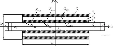
Fig.1 Multilayer sound absorbing material straight-through perforated pipe muffler
In the acoustic finite element calculation, the interpolation function is used to represent the sound pressure
Pi={N}T{Pi},
(5)
where {Pi} (i=1, 2, …, 4) is the column vector of sound pressure of each node in regionAi(i=1, 2, …, 4); and {N} is the column vector of the shape function.
There are four types of boundary conditions for perforated pipe mufflers[13-14].
(a) Rigid wall boundary conditions, in which the vibration velocity of the normal particle is zero,
(6)
(b) The perforated tube exists at the interface between air and sound-absorbing material. In this case, the velocity of the normal particle is continuous and the normal pressure gradient on both sides is in direct proportion to the density ratio:
ua·na=-ub·nb,
(7)
(8)
whereuais particle vibration velocity on the air side;ubis the particle vibration velocity on the side of sound absorbing material;ρais air density;ρbis the density of sound absorbing material;nais the unit external normal force on the air side of the perforated pipe wall;nbis the unit external normal force on the sound-absorbing material side. Therefore, the relationship between the sound pressure difference on both sides of the perforated wall and the vibration velocity of the normal particleuncan be established through the characteristic acoustic impedance of the perforated pipe.
(i) If the sound first passes through the air layer and enters the sound-absorbing material through the perforated element,
(9)
(ii) If the sound first passes through the sound absorbing material and enters the air layer through the perforated element,
(10)
whereζpis the characteristic acoustic impedance of the perforated pipe;Ppais the sound pressure of the perforated tube on both sides of the air side;Ppbis the sound pressure of the sound-absorbing material on either side of the perforated pipe. The perforated tube is a thin-walled structure with a high perforation rate and uniform distribution of holes. The momentum equation is used to obtain,
(11)
(12)
(c) If the boundary condition of the inlet is known, then
(13)
(d) If the outlet is set to a non-reflective boundary condition, then
(14)
Using the Galerkin weighted parameter method[15]in regionA1, it can be
(15)
From the transformation of Green's formula, we can obtain

(16)
Using the same method in areasA2,A3andA4, respectively, we can obtain
(17)
(18)
(19)
According to Fig.1, Eqs. (6)- (7), Eqs. (11)- (14) are substituted into Eqs. (16)-(19)by using applicable conditions, the following rearranged formulaA1,A2,A3, andA4can be obtained
(20)
(21)
(22)
(23)
Add Eqs. (20)-(23) and substitute Eq. (5) into the formula:
(24)
In the above formula:
(25)
(26)
(27)
(28)
(29)
(30)
(31)
(32)
(33)
(34)
(35)
(36)
(37)
(38)
(39)
(40)
The sound pressure at each node can be obtained by solving Eq.(24), and then the transmission loss of the muffler can be calculated according to Eq. (41). The expression of the transmission loss (L) is[16]
(41)
whereS1is the cross-sectional area of the muffler inlet;S2is the muffler outlet cross-sectional area;Piis the muffler inlet incident sound pressure;Pois the muffler outlet transmission sound pressure.
2 Acoustic Characteristics of Sound Absorbing Material and Perforation Acoustic Impedance
The sound absorbing material inside the muffler is ideal status to be uniform adiabatic and equivalent to a fluid with complex sound velocity and density. The internal structure of the sound-absorbing material is complex, and its acoustic characteristics are not easy to be obtained and are generally obtained through experimental measurement[17]. The expressions of complex impedance and complex wave number of sound absorbing materials used in this paper are[18]
Z′/Z0=[1+0.085 5(f/R)-0.754]+
j[-0.076 5(f/R)-0.732],
(42)
k′/k0=[1-0.147 2(f/R)-0.577]+
j[-0.173 4(f/R)-0.595],
(43)
wherefis the frequency;Z' is the complex impedance of sound-absorbing material;k′ is the complex wave number of the sound-absorbing material;Z0=ρ0c0is air characteristic acoustic impedance;k0=2πf/c0is the wave number in the air (air densityρ0=1.156 kg/m3and sound speedc0=340 m/s);Ris the flow resistance rate of the sound-absorbing materials (fiberglass silk cotton). When the filling density of sound-absorbing material is 100 kg/m3, the flow resistance rate is 5 000 N/m2, and when it is 200 kg/m3, the flow resistance rate of this material is 15 000 N/m2. The flow resistance rate of the sound-absorbing material is measured with the standing wave tube[19]. The complex sound velocity and density of the sound-absorbing materials are
(44)
(45)
Because the media on both sides of the perforated tube are different, air on one side and the sound-absorbing material on the other side, the modified acoustic impedance expression of perforated characteristicsξp[20]is
ξp=(0.006+jka[t+0.375dh(1+Zbka)]),
(46)
wheredhrepresents the thickness of the cavity.
3 Discussion and Analysis
Figure 2 is the three-dimensional picture of the multilayer sound absorbing material straight-through perforated pipe muffler.Its specific dimensions are the expansion cavity lengthL=500 mm, the expansion cavity heightH=140 mm, three layers of the micro-perforated pipe, the distance between each layer of micro-perforated tube is 10 mm, the areasA2andA4are porous sound absorbing materials, the areaA3is the cavity (the cavity set after the micro-perforated plate can form a resonance cavity), the inner diameterD1=D2=50 mm, the sound speedc0=340 m/s. The basic parameters of sound absorbing materials (including micro-perforated plates and porous sound-absorbing materials) are set as shown in Table 1.
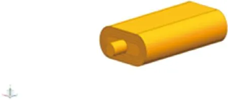
Fig.2 Three-dimensional model of multi-layer sound absorbing material straight-through perforated pipe muffler
The multilayer sound-absorbing material straight-through perforated pipe muffler is divided into finite element meshes with the free quadrilateral body, and the meshes contain 51 524 domain elements, 19 074 boundary elements and 10 491 nodes. The meshing diagram is shown in Fig.3.
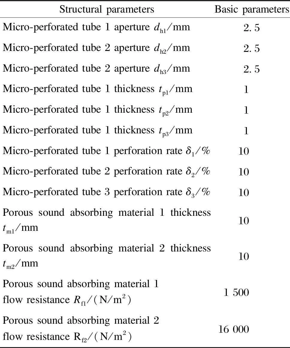
Table 1 Basic parameters of sound absorbing materials
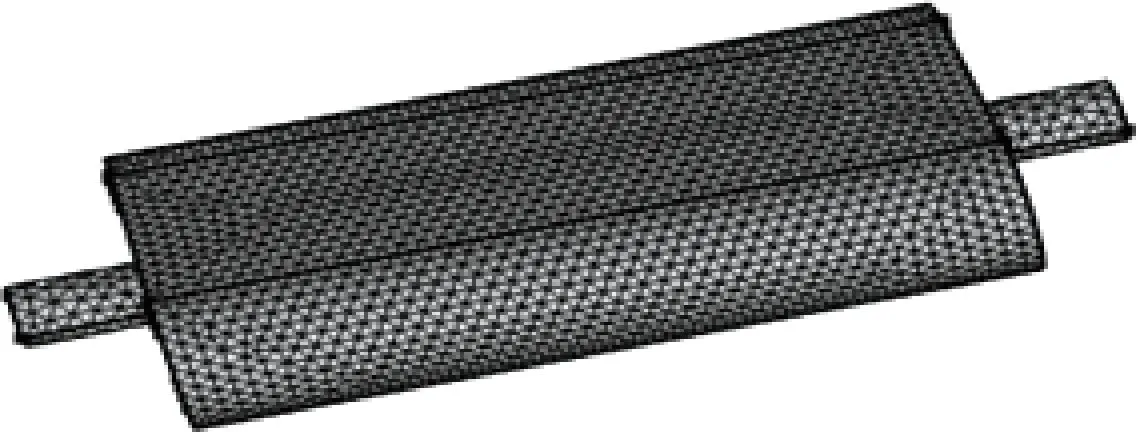
Fig.3 Finite element mesh of multilayer sound-absorbing material straight-through perforated pipe muffler
The experimental schematic of transfer loss is shown in Fig.4.
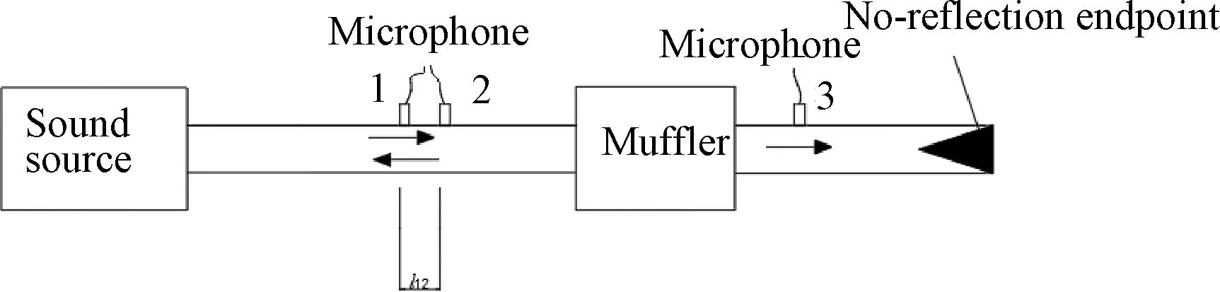
Fig.4 Experimental schematic of transfer loss
According to the experimental schematic diagram in Fig.4, the experimental block diagram of muffler transmission loss shown in Fig.5 can be designed.
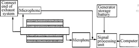
Fig.5 Experimental block diagram for measurement of transmission loss of multilayer sound-absorbing material straight-through perforated pipe muffler
The experimental platform as shown in Fig.6 is built according to the experimental block diagram.
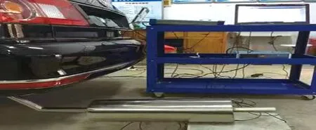
Fig.6 Experimental platform for measurement of transmission loss of multi-layer sound absorbing material straight-through perforated pipe muffler
3.1 Verification of numerical calculation results
In order to verify the correctness of the finite element method used to study the multi-layer sound absorbing material straight-through perforated tube muffler, the finite element results are compared with the experimental results, as shown in Fig.7. It can be seen that the muffler with multi-layer sound-absorbing material straight-through perforated pipe muffler has much better muffler effect than that with the resistant muffler. The results of the finite element calculation and experimental measurement are in good agreement in the whole frequency range, which indicate that the finite element method can accurately predict the acoustic characteristics of the multilayer sound absorbing material straight-through the perforated pipe muffler. The viscous damping effect is the reason for the error between the experimental results and the simulation results at high frequency.
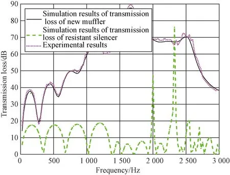
Fig.7 Simulation results of transmission loss compared with experimental results
3.2 Influence of flow resistance rate on transmission loss
Flow resistance is one of the important parameters of porous sound absorbing materials. It affects the complex impedance and the complex wave number of porous sound absorbing material and perforated acoustic impedance, and ultimately affects the acoustic characteristics of the muffler[21]. The porous media with low flow resistance (1 500 N/m2) and high flow resistance (16 000 N/m2) were combined in pairs to conduct the research. The transmission loss is shown in Fig.8. It can be seen from Fig.8 that in the low-frequency regions, porous medium 1 and porous medium 2 have little influence on the transmission loss regardless of the low or high flow resistance; while in the high-frequency regions, porous medium 1 and porous medium 2 have better flow resistance, and the sound attenuation effect is better. When porous medium 1 has a low flow resistance rate and porous medium 2 has a high flow resistance rate, the noise frequency before 1 750 Hz has a good noise attenuation effect. When porous medium 1 has a high flow resistance rate and porous medium 2 has a low flow resistance rate, the noise frequency after 1 750 Hz has a good noise attenuation effect. In order to reduce the mass of the muffler, the bulk density of the porous media could be reduced, and the flow resistance of each layer of the porous media could be selected according to the noise reduction requirements.
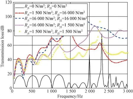
Fig.8 Influence of flow resistance rate on transmission loss
3.3 Effect of micro-perforated pipe thickness on transmission loss
The influence of thicknessestp1,tp2andtp3of micro-perforated pipe 1, perforated pipe 2 and perforated pipe 3 on the transmission loss is shown in Fig.10.
As can be seen from Fig.9(a), at the noise frequency lower than 1 500 Hz, the transmission loss is the largest when the thickness of perforated pipe 1tp1=1 mm; at the moise frequency higher than 1 500 Hz, the transmission loss is the largest whentp1=2 mm, followed by the transmission loss attp1=3 mm, and the transmission loss is the smallest attp1=4 mm is between 1 500 Hz and 2 300 Hz. At about 2 500 Hz, there is a sharp increase in the transmission loss whentp1=4 mm, because at about 2 500 Hz, perforated pipe 1 reaches the resonant frequency of noise and produces resonance, followed by a sharp decline. It can be seen from Fig.9(b) thattp2=1 mm has the largest transmission loss before 1 500 Hz, and there is almost no difference in transmission loss whentp2is 2, 3 and 4 mm, respectively. At the noise frequency about 1 550 Hz, the transfer loss attp2=4 mm reaches the resonant peak, following by a sharp decline. After the noise frequency of 1 550 Hz, the transmission loss oftp2=2 mm is the largest, the muffler frequency band is the widest, and the muffler effect is the best. It can be seen from Fig.9(c) that the thickness of perforated pipe 2 has little influence on the transmission loss before the noise frequency of 2 200 Hz, but at about 1 500 Hz, the transmission loss oftp3=4 mm reaches the resonance peak. After the noise frequency of 2 200 Hz, the larger the thickness of micro-perforated pipe 3, the smaller the transmission loss.
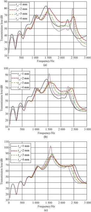
Fig.9 Effect of different thicknesses of micro-perforated pipe on transmission loss: (a) perforated pipe 1; (b) perforated pipe 2; (c) perforated pipe 3
3.4 Influence of perforation rate of micro-perforated pipe on transmission loss
The effect of perforation ratesδ1,δ2andδ3of micro-perforated pipes 1, 2 and 3 on the transfer loss is shown in Fig.10.
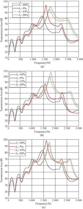
Fig.10 Effect of perforation rate of different micro-perforated pipes on transfer loss: (a) perforated pipe 1; (b) perforated pipe 2; (c) perforated pipe 3
As can be seen from Fig.10, when the perforation rate of micro-perforated pipes 1, 2 and 3 is 10%, the transmission loss is the greatest and the noise attenuation effect is the best.At the noise frequency lower than 1 500 Hz, when the perforation rate of the three pipes is equal to 5%, the transmission loss reaches the resonance peak and then decline sharply around 1 550 Hz. When the perforation rate of the three micro-perforated tubes is 20%, the transmission loss is the largest, and the sound attenuation effect is good. The reason is that in the high-frequency stage, the larger the perforation rate of the micro-perforated pipe, the more high-frequency noise passes through the micro-perforation. The more high-frequency noise is absorbed by the porous sound absorbing material, the sound attenuation effect is better.
3.5 Influence of center distance of inlet and outlet pipe on transmission loss
In order to study the influence of distance between the axes inlet and outlet on the transmission loss, the distance of the inlet and outlet was set as 0, 50, 100 and 150 mm, respectively. Its plane diagram is shown in Fig.11, where the center distance of inlet and outlet pipes isl. The results are shown in Fig.12.
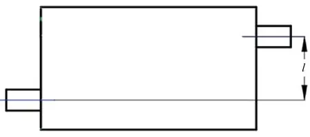
Fig.11 Layout diagram of distance between the axes inlet and outlet
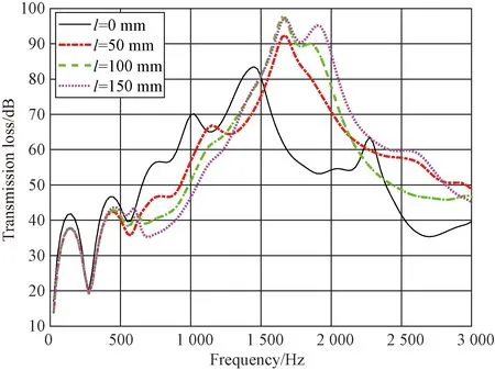
Fig.12 Influence of center distance of inlet and outlet pipes on transmission loss
It can be seen from Fig.12 that in the low-frequency band, at the noise frequency lower than 1 400 Hz, the transmission loss is the largest whenl=0 mm. The noise frequency is 1 400-1 600 Hz, the transmission loss is almost the same atl=50 mm andl=100 mm. In the high-frequency band higher than 1 600 Hz, the distance between the axes of inlet and outlet for the transmission loss is biggest atl= 150 mm. Because this arrangement makes the propagation path longer, the high-frequency noise is absorbed more by the absorbing porous medium.The better noise reduction effect can be achieved. Therefore, in order to design a muffler with a better effect, the center distance between the axes of inlet and outlet pipe can be properly deviated.
4 Conclusions
The finite element method is used to calculate the acoustic characteristics of the muffler based on multilayer sound absorbing materials. The finite element calculation results of the muffler based on multilayer sound absorbing material straight-through perforated pipe agree well with the experimental measurement results, which indicates the reliability of the finite element method used to study the acoustic performance of the muffler based on multi-layer sound absorbing material straight-through perforated pipe muffler. Through the influence of racetrack cross section multi-layer sound absorbing material directly through the perforated pipe muffler, some structural parameters of the perforated plate and the center distance between the inlet and outlet of the pipe on the acoustic performance of the muffler, the following conclusions are drawn.
1) Among the above parameters, the aperture of perforated pipe 1 and the thickness of perforated pipe 3 have little influence on the acoustic performance of the muffler at low frequencies. The other parameters are the basic parameters in Table 1. The muffler has a good noise attenuation characteristic in the low-frequency bands.
2) In the high-frequency bands, the smaller the aperture of the perforated pipe, the greater the transmission loss of the muffler. With the increase of the perforation rate and the distance between the inlet and outlet of the perforated pipe, the high-frequency transmission loss in the muffler increases. The thicknesses of perforated pipes 1, 2 and 3 do not show strong regularity in middle and high-frequency bands, so it is necessary to select appropriate values to achieve large transmission loss.
3) Different from the traditional straight-through perforated pipe muffler, this paper applies the multilayer sound absorbing material to the straight-through perforated pipe muffler. The new type muffler increases the transmission loss and improves the sound attenuation effect of the straight-through perforated pipe muffler, which has strong guiding significance and application value for the future research of such mufflers.
杂志排行

Journal of Donghua University(English Edition)的其它文章
- Preparation of Cellulose Acetate Butyrate Porous Micro/Nanofibrous Membranes and Their Properties
- Highly Sensitive Electrochemical Detection of Nitrite Based on Cationic Surfactant Modification of Conductive Carbon Black
- Concise Synthesis and Fertility-Promoting Activity of Thiamidol
- Design and Structure Optimization of Plenum Chamber with Airfoil Baffle to Improve Its Outlet Velocity Uniformity in Heat Setting Machines
- Modeling of Micropores Drilling Force for Printed Circuit Board Micro-holes Based on Energy Method
- Image Retrieval Based on Vision Transformer and Masked Learning