Development and preliminary results of a large-pixel two-layer LaBr3 Compton camera prototype
2023-09-18MingHaoDongZhiYangYaoYongShunXiao
Ming-Hao Dong · Zhi-Yang Yao · Yong-Shun Xiao
Abstract Lanthanum bromide (LaBr3) crystal has a high energy resolution and time resolution and has been used in Compton cameras(CCs) over the past few decades.However, LaBr3 crystal arrays are difficult to process because LaBr3 is easy to crack and break; thus, few LaBr3-based CC prototypes have been built.In this study, we designed and fabricated a large-pixel LaBr3 CC prototype and evaluated its performance with regard to position, energy, and angular resolution.We used two 10 × 10 LaBr3 crystal arrays with a pixel size of 5 mm × 5 mm, silicon photomultipliers (SiPMs), and corresponding decoding circuits to construct our prototype.Additionally, a framework based on a Voronoi diagram and a lookup table was developed for list-mode projection data acquisition.Monte Carlo (MC) simulations based on Geant4 and experiments were conducted to evaluate the performance of our CC prototype.The lateral position resolution was 5 mm, and the maximum deviation in the depth direction was 2.5 and 5 mm for the scatterer and absorber, respectively.The corresponding measured energy resolutions were 7.65% and 8.44%, respectively, at 511 keV.The experimental results of 137Cs point-like sources were consistent with the MC simulation results with regard to the spatial positions and full widths at half maximum (FWHMs).The angular resolution of the fabricated prototype was approximately 6° when a point-like 137Cs source was centrally placed at a distance of 5 cm from the scatterer.We proposed and investigated a large-pixel LaBr3 CC for the first time and verified its feasibility for use in accurate spatial positioning of radiative sources with a high angular resolution.The proposed CC can satisfy the requirements of radiative source imaging and positioning in the nuclear industry and medical applications.
Keywords Compton camera · Large pixel · Gamma camera · LaBr3 detector · Prototype evaluation
1 Introduction
To overcome the low detection efficiency of traditional image-forming systems for high-energy gamma rays, the Compton camera (CC) was proposed in 1974 [1].The CC uses electronic collimation rather than mechanical collimation; therefore, it has a wider field of view (FOV) and higher detection efficiency.It can be used for detecting gamma rays over a wide energy range of 100 keV-10 MeV, which covers natural radioactivity of nuclear materials and waste[2-4] and the typical gamma-ray energy used in medical applications such as radiopharmaceutical imaging [5-8] and prompt gamma imaging [9-11].The earliest prototype of a CC was a single-layer system that could distinguish the photon scattering position and the photon-absorbed position with a single layer of scintillator detector.However, owing to the limitations of the detector material and data-acquisition technology, the CC was not applied in practice.
To improve the performance of the CC, several CC prototypes have been proposed and built over the past few decades.CC prototypes can be divided into two main categories: single-layer and multilayer.The single-layer CCs are similar to the earliest CCs prototypes but are based on the latest developments of detector materials and circuit readout technology.Among them, the three-dimensional (3D) cadmium zinc telluride (CZT) CC is the representative singlelayer CC.Considerable research on the 3D CZT CC has been performed, and prototypes have been developed [12].Single-layer CCs have the advantages of a large FOV of 4π,high spatial resolution, and high energy resolution; however,the detector material is expensive.Additionally, the distance between the scattering position and the absorbed position is far shorter than that in multilayer CC, resulting in a larger deviation of the spatial orientation of Compton cones.Multilayer CCs determine the scattering position and the absorbed position in separated detectors; thus, only photons incident in a specific direction are received.Multilayer CCs have been developed and used in the detection of radioactive materials [13] and prompt gamma imaging during hadron therapy [14].Among the multilayer CCs, three- or morelayer CCs have a high detection efficiency, but they are more expensive than two-layer CCs while having comparable performance, and the probability of three-point interaction events is far lower than that of two-point interaction events[15].Thus, two-layer CCs are the mainstream prototypes for multilayer CCs.
The scintillator materials used in CCs have been researched in the past few years [16-19].The scintillator material has relatively high detection efficiency and time resolution.There are many types of scintillators, such as LYSO, GAGG, and lanthanum bromide (LaBr3).Each has advantages and disadvantages.Thus, different scintillators have been used in CCs for different purposes.LYSO and GAGG crystals have higher densities (7.2 and 6.6 g/cm3,respectively) than LaBr3.However, LYSO has background radiation ranging from 88 to 597 keV, which reduces the energy resolution-particularly for detecting natural radioactivity [20].Additionally, GAGG has a long light decay time of approximately 90 ns, making it easier to obtain an error coincidence energy signal compared with the 20-ns coincidence time window used in this study.The LaBr3scintillator has a light decay time of 20 ns and relatively low intrinsic background radiation.Moreover, it has the highest energy resolution among the three outstanding and cost-effective scintillators.Extensive research has been conducted on the LaBr3scintillator owing to its excellent performance [21-24].Therefore, it was used in our CC prototype in this study.
The existing CC prototypes usually have a small pixel size(e.g., 1 mm × 1 mm) and a large number of pixels in every layer (e.g., several hundreds of pixels per layer) for obtaining accurate reconstruction results.There has been little research on the influence of the large pixel size of the CC on the reconstruction accuracy.Additionally, the LaBr3crystal is easy to crack and break during processing, making it difficult to obtain small-pixel size LaBr3crystal arrays.Among the research on LaBr3-based CCs, only MACACO had a small pixel size (3 mm × 3 mm) [15].Although a large pixel size leads to a low position resolution, one promising solution is using the reconstruction algorithm with resolution recovery(RR).Recently, RR-based reconstruction algorithms have proven to be useful in correcting the error caused by the limited resolutions of actual CCs [25, 26].Among them,RR-based maximum likelihood expectation-maximization(MLEM) [6] and origin ensemble (OE) [7] algorithms have attracted considerable attention, and optimization methods such as graphics processing unit (GPU) acceleration [6] and deep learning [8] have been applied.Additionally, radioactive source imaging with a CC prototype during nuclear decommissioning based on the subset-driven origin ensemble with resolution recovery (SD-OE-RR) algorithm was demonstrated [3].Thus, CC systems with large pixel sizes are expected to reconstruct images with a high spatial resolution with the help of RR-based reconstruction algorithms,making them promising for practical applications.
In this study, we developed and evaluated a two-layer LaBr3CC prototype with a large pixel size for nuclear material and waste detection.Two LaBr3crystal arrays with a relatively large pixel size of 5 mm × 5 mm × 5 (10) mm,silicon photomultipliers (SiPMs), and coding circuits were used to construct our prototype.We used a data-acquisition card (DAQ) to select and decode the coincidence events and developed a framework to obtain the list-mode data from time-series projection data including the interaction positions and energies deposited in the scatterer and absorber.Finally, we evaluated the performance of our prototype via simulations and preliminary experiments.
2 Materials and methods
2.1 Structure of two-layer LaBr3 Compton camera prototype
The LaBr3CC prototype consisted of a scatterer and an absorber, both of which had the same cross-sectional area.As shown in Fig.1, the LaBr3detectors consisted of a 10 × 10 LaBr3array with a thickness of 5 mm for the scatterer and 10 mm for the absorber (Kinheng Crystal,Shanghai, China) and a coding circuit module that contained the SiPM (TOFTEK, Wuxi, China).The pixel size of the LaBr3array was 5 mm × 5 mm × 5 (10) mm, and the pixels were separated by a 0.1-mm BaSO4spacer.A 1-mm-thick glass plate and a 1.2-mm-thick Al shell were used for vacuum packing.The volume of the LaBr3array was 56.4 mm × 56.4 mm × 9.3 (14.3) mm.Both layers had a coding circuit module behind the scintillator arrays,which included an 8 × 8 array of SiPMs and a 4-channel output encoding circuit.The voltage values of the 64-channel signals output from the SiPMs were proportional to the number of scintillating photons distributed in the corresponding area of 64 SiPM pixels.The 4-channel output encoding circuit transferred the 64-channel signals of the SiPMs to the 4-channel output through a resistance weight network.Finally, the output signals were input into the DAQ (TOFTEK, Wuxi, China).The eight signals (four channels from the scatterer and four channels from the absorber) were input into the same DAQ simultaneously,and the DAQ outputs the total voltage values of the eight signals in every time window.The two layers were fixed by a 3D-printed resin bracket.The distance between the center of the two LaBr3arrays was adjustable, and the default value was 50 mm.
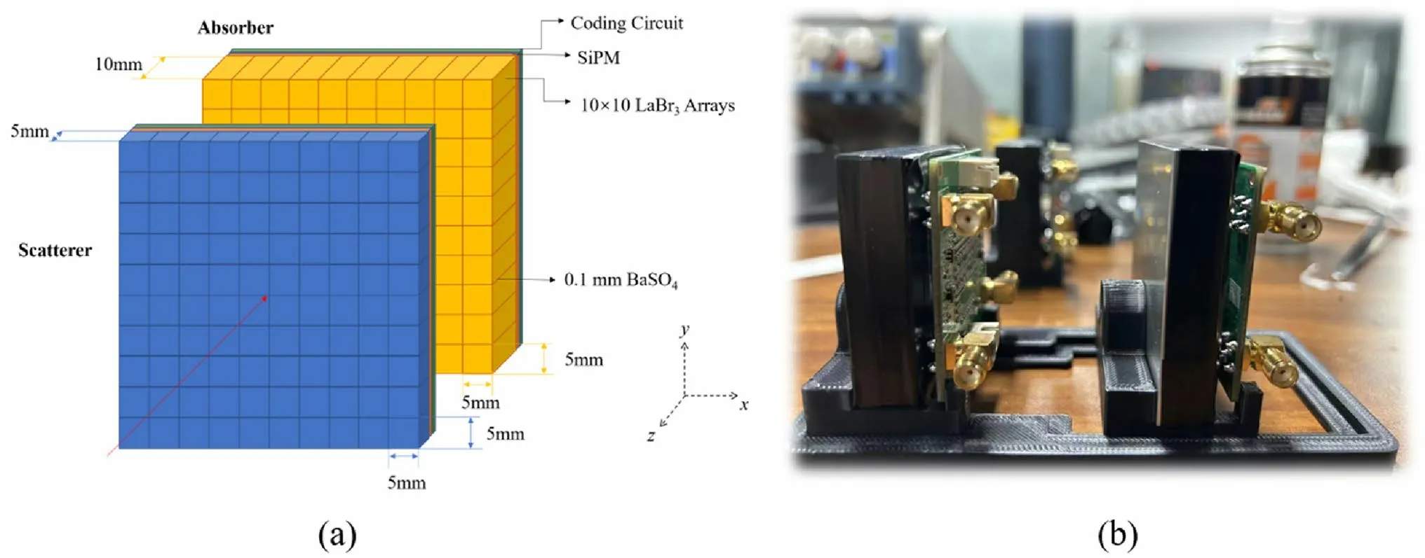
Fig.1 (Color online) Fabricated two-layer LaBr3 CC prototype: a structure diagram; b photograph
3 List-mode data acquisition through lookup table
The DAQ output a row of data including nine integers: a timestamp andV1-V8.V1-V8were the eight voltage signals;V1-V4were the scatterer voltage signals, andV5-V8were the absorber voltage signals.The subscripts from smallest to largest corresponded toA,B,C, andDin Fig.2.The positions in scatterplots (xV1,yV1,xV2,yV2) where the scintillating photons were generated and received were calculated via the method used in the Anger camera [27].

Fig.2 (Color online) Encoding circuit and position decoding diagram: a structure diagram of the LaBr3 CC detector; b photograph of the LaBr3 detector
Here,ρis the gain factor used to discretize the interaction positions.By default, we setρ=0.78125 , and the corresponding 512 × 512 pixelated space was used to store and display the original scatter plot.
Because the responses to the scintillating photons varied among different crystals and positions, the original scatterplot did not exhibit a standard scattered point array.A connection between the initial scatterplots and the pixel coordinates of the crystal arrays was established via the following steps.The original scatterplot was subjected to image processing, e.g., enhancement, denoising, and smoothing, whereby the most representative positions of different scatters were found and marked with a crystal index.Then, a Voronoi diagram whose seed points were the selected positions was created according to the principle of the minimum distance between position seeds and every point in the scatterplot [28].Using the diagram,a lookup table (LUT) of photon events’ decoded positions and corresponding crystal indices was constructed.Through the LUT, the acting positions of gamma photons were efficiently determined.In the study, we used the center coordinates of the crystal pixel to represent the spatial position where the gamma photon interacted with the detectors to achieve the optimal estimation.Thus, the lateral position resolution was 5 mm, and the maximum deviation in the depth direction was 2.5 and 5 mm for the scatterer and absorber, respectively.
The next step was to obtain the energy responses of different crystals.The sum of the voltage signals of all the layers is the address of the channel in the energy spectrum.Every crystal unit must be calibrated using the following formula:
whereeijrepresents the deposited energy in theith pixels of thejth layer, andaijandbijare the parameters.Three types of natural radioactive sources (22Na,57Co, and137Cs) and their four characteristic energies were used for energy calibration.
For every two-point event, the output list-mode data were in the format of (x1,y1,z1,e1,x2,y2,z2,e2).Here,x1,y1,z1represented the interaction position in the scatter.x1andy1represented the lateral position depending on the crystal pixel the event clustered to.z1represented the position in the depth direction and was set as a constant (0 mm).x2represented the interaction position in the absorber, andz2was set to - 50 mm.In some cases,L1andL2were used to replacex1,y1,z1andx2,y2,z2, respectively.e1ande2represented the deposited energy in the scatterer and absorber,respectively, calculated via Eq.(5) (Fig.3).
As the developed prototype is expected to be used in detecting sources that may emit photons of different energies, event selection methods are used in projection data acquisition to obtain the valid events used for reconstruction.In our study, the characteristic energy window depended on prior knowledge, or the measured energy spectrum was used to select events with certain total deposited energies for corresponding radioactive sources.In addition, if only locating the radioactive sources and reconstructing the relative activity were needed, a large energy window that covered all the characteristic energies but eliminated noise was allowed,because the CC could reconstruct the locations and activities of sources where photons with different energies would make equal contributions in the formula of back-projected Compton cones.
4 Reconstruction algorithm
In this study, the previously proposed SD-OE-RR algorithm was used for reconstruction [3].It is an optimized origin ensemble (OE) algorithm that was developed for CC reconstruction in a large FOV with a projected coordinate system (θx,θy,z) during nuclear decommissioning source term investigation, and it can also be used to evaluate the angular resolution of the proposed LaBr3CC prototype.The OE algorithm has been proven to have the same estimate as the MLEM algorithm under some approximation [29].However,OE algorithms have reconstruction speeds several orders of magnitude higher than that of the MLEM algorithm [26].

Fig.3 Framework of the list-mode projection data acquisition for the prototype
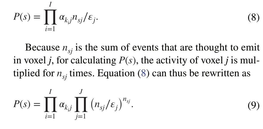
OE algorithms use transitions of different states as the iterative process.In a typical case of locating gamma rays,the detector withKbins receivesIevents from the image volume divided intoJvoxels.States can be defined as the locations ofIevents assigned toJvoxels individually; in this case, there areJIstates.The reconstruction process finds the most probable state.The probability of a certain stateswas defined as the product of the probability that events emitting in the certain voxel, as follows:
whereP(s) represents the probability of statesandpsnirepresents the probability that the origin of eventiis located in voxelj(while eventiwas thought to be located in voxeljin states).psijcan be defined as follows:
whereαkijrepresents the probability that eventidetected in binkemits in voxelj, which is the differential cross section of the current scattering angle and is calculated via the Klein-Nishina formula in the CC system.nsjrepresents the number of events whose origin is in voxeljin states, andεjrepresents the sensitivity of voxeljto the detector.Thus,nsj∕εjis the estimate of the activity of voxeljin states.In this case, Eq.(6) can be rewritten as
A higherP(s) indicates that the state is closer to the optimal estimation; thus, the OE algorithm iterates by comparing the probabilities of two adjacent states and transforming the current state.Here, “adjacent states” refers to two states that differ in the location of only one event.The probability ratio can be simplified as follows:

Usually, the initial estimate of activity has no restrictions,but a more accurate initial state will lead to a higher convergence rate and a better reconstruction result.In the OE algorithm, events are stochastically assigned to the voxel that is on the corresponding Compton cone as an initial state.However, owing to the finite energy resolution and position resolution of the detector and the Doppler broadening effect,the Compton cone calculated using the list-mode data cannot cover all the possible voxels where the event really emitted.In the SD-OE-RR algorithm, these effects on the angular resolution are considered.The influence of the energy resolution and the Doppler effect on the deviation of the calculated scattering angle can be expressed as follows [3]:
whereδrepresents the energy resolution of the detectors,andE2, ΔE2s, and ΔEdopplerrepresent the deposited energy in the absorber, the energy deviation of the deposited energy in the absorber in terms of statistical fluctuations, and the energy deviation caused by the Doppler broadening effect,respectively.m0c2represents the static energy of the electron.For the position resolution, the effects of the interaction position deviation on the deviation of the scatter angle can be expressed as follows [30]:

In contrast to the OE algorithm, the SD-OE-RR algorithm stores all the voxels’ indices (subsets of the OEs)by traversing all possible voxels of photon events with the cones and deviations via Eq.(15).Δ(cosθi) was 0.06 for the fabricated LaBr3CC prototype, as given by Eqs.(12)-(14).
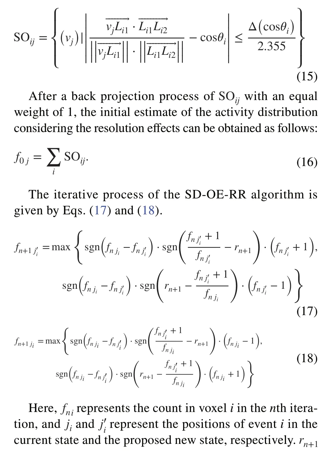
Step 1: Calculate the deviations Δ(cosθ) of all photon event cones by using Eq.(14) with the position and energy uncertainties and the Doppler broadening effect.Use Eq.(15) to obtain the subsets of the OEs of eventi.
Step 2: Use the sum of all the initial event counts of the voxels in SOijas an initial estimate of the source distribution.
Step 3: Randomly select one eventi.Randomly select a new location (i.e., voxelj′) of this event in theith row vector of SOijfor states′.Obtain the corresponding event countsnj′andnjof the voxel where eventIis located for statessands′, respectively.
Step 4: Determine the acceptance probabilityAfor the new location of eventiby using Eq.(19) and generate a random number α uniformly distributed between 0 and 1.
Step 5: Eventimoves to the new location ifA >α and remains at the current location ifA≤α.The voxel where eventiis located after the above operation becomes the old location of the next iteration, and the corresponding event counts of the voxels in SOijare updated.
Step 6: Repeating Steps 2-4Ntimes corresponds to one full iteration of the algorithm.After a sufficient number of iterations (3 × 10⁶), the event counts in the voxels are approximately invariant, and the reconstructed image is obtained by summing all the weights of the same voxel in the sparse matrix SOij.
4.1 Monte Carlo simulation
Geant4 p10.03 was used to model the CC with the same structure and position and energy resolutions as the fabricated CC prototype.The Doppler broadening effect was included in the simulations.Four simulations were conducted to evaluate the angular resolutions of the CC with different angles, distances, source areas, and source energies.
(i) Angular resolutions with different angles: an ideal point-like source was placed at 25 positions along the lateral and diagonal directions in the FOV (Fig.4).The distance between the source and the scatterer of the CC was 10 cm.
(ii) Angular resolutions with different distances: an ideal point-like source was placed at the center of the FOV,and the distance between the source and the scatterer of the CC was varied from 5 cm to 1 m.
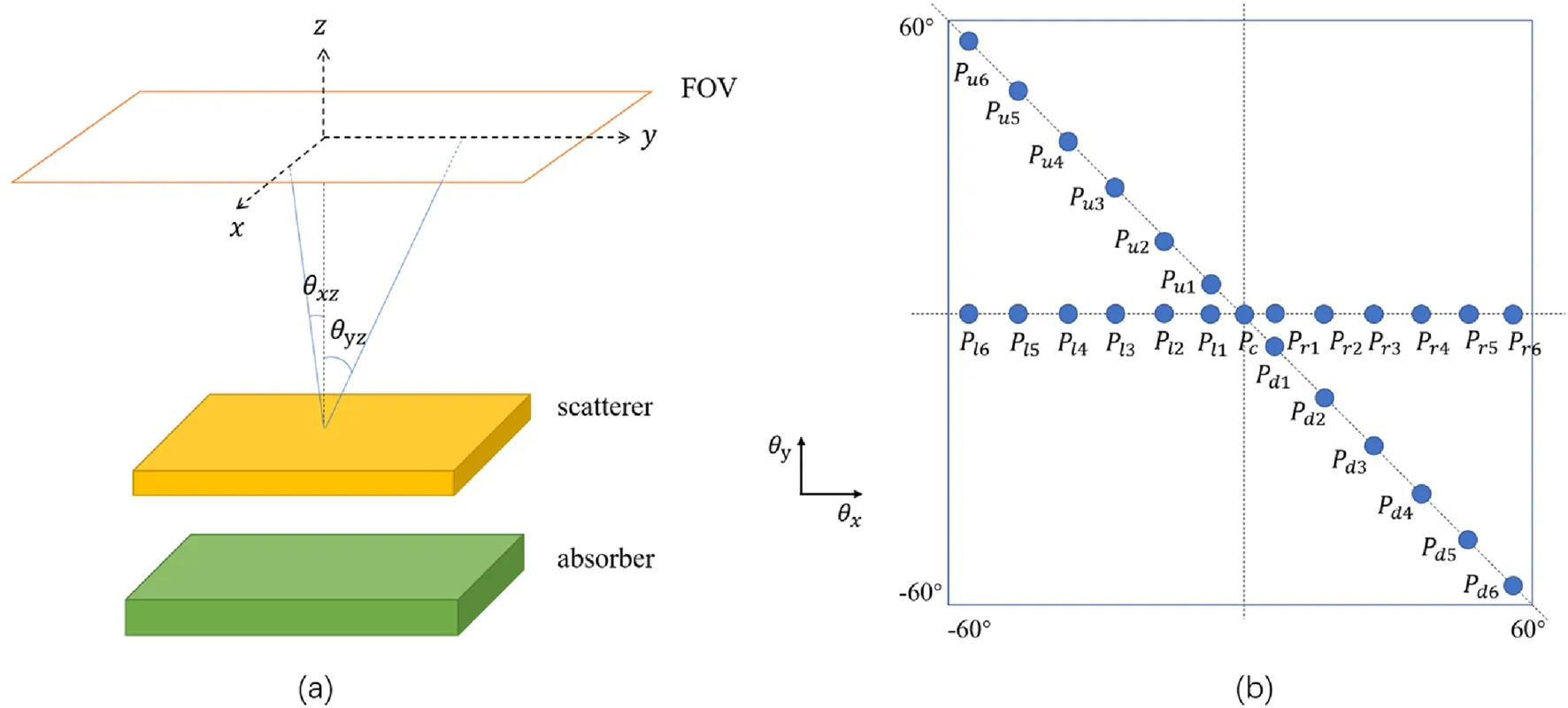
Fig.4 (Color online) a Setup of the LaBr3 CC in the simulation.b Schematic of simulated ideal point-like sources in the FOV
(iii) Angular resolutions of sources with different areas:circular plane sources with radii varying from 0.5 to 5 cm were placed at the center of the FOV, and the distance between the source and the scatterer of the CC was 10 cm.
(iv) Angular resolutions of sources with different energies: an ideal point-like source was placed at the center of the FOV.The energy of the source was set as 511, 662, and 1275 keV for single-energy source simulation.For multiple-energy sources, the energy of the source was set as a combination of two of the aforementioned three energies, with each energy accounting for 50%.Another combination of 64.3%511 keV and 35.7% 1275 keV was used as an imitation of a real22Na source.The distance between the source and the scatterer of the CC was 5 cm.Because the variation caused by the deviation of the energy was relatively small, a short distance would amplify the variation and make it more perceptible.
Approximately 10,000 events were used for reconstruction in each simulation.The projection data obtained in the simulations considered the position resolution and energy resolution of the CC, which were consistent with the fabricated prototype, as well as the Doppler broadening effect.The lateral positions of the events were moved to the center coordinates of the nearest pixels.The positions in the depth direction were set as 0 or - 50 mm for the scatterer and absorber.The deposition energy was degraded by Gaussian noise representing the uncertainty caused by the Doppler broadening effect and energy resolution.As the noise and the simulation data were stochastic, the results were the averages of five reconstructions under the same condition.
The aforementioned angular resolution was defined as follows in a plane coordinate system [32]:
where FWHMorepresents the mean value of the full widths at half maximum (FWHMs) in the profiles taken from different angles through the source, anddrepresents the distance between the source and the scatterer.For the projected coordinate system used in this study, Eq.(20) is transformed into
where FWHMahas a similar definition to FWHMoexcept that FWHMawas measured in projected coordinates with the unit of degrees,φrepresents the angle between theZ-axis and the line passing through the source and the center of the scatterer.For convenience, the FWHM is used to representσθhereinafter, and it has units of degrees.
5 Experiments
In the experiments, a point-like137Cs source with activity of approximately 9000 Bq was placed at three positions matching those used in the simulations labeledPl2,Pc, andPd2.The distance between the source and the scatterer of the prototype was 5 cm.Each measurement took 5 min.The numbers of obtained coincident events with a total energy of 600-700 keV were 315, 360, and 205, respectively (Fig.5).
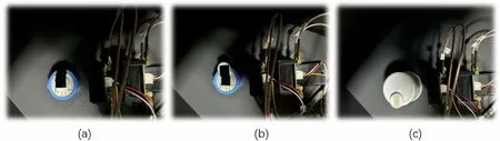
Fig.5 (Color online) 137Cs point-like source imaging experiments involving the LaBr3 CC prototype at three positions

Fig.6 (Color online) a, b Initial scatterplots of the scatterer and absorber from 22Na obtained using the decoding Eqs.(1)-(4).c, d Voronoi diagram of each layer.e, f Corresponding decoding interaction positions
6 Results
6.1 Position decoding and energy spectrum calibration
The scatterplots of the scatterer and absorber constructed using the detection results of the22Na source are shown in Fig.6.An LUT was created after numbering all the centroids, providing a fast-clustering method.The distances between all the pixel points in the scatterplots and every centroid of the point group were compared; each pixel was labeled with the number of the nearest centroid.Two Voronoi diagrams of each layer are shown in Fig.6c, d.In the diagrams, the scatterplots are segmented by the white line,indicating that any event decoded in a single area would be clustered to the corresponding scatter and pixel.The final decoding interaction positions of all the events are also shown in Fig.6.
To obtain the total energy response of the scatterer and absorber, the energy responses of every crystal were measured and calibrated.22Na,57Co, and137Cs and their characteristic energies of 122, 511, 662, and 1275 keV were used for calibration through experiments.Figure 7 shows the energy responses of a pixel in the corner, an edge pixel,and a center pixel to the22Na source.The calibration result of the positive center pixel is also shown as a typical result.The energy resolution of each layer was evaluated using the total energy spectrum obtained from all pixels.The mean energy resolution of the scatterer was 20.63% at 122 keV,7.64% at 511 keV, 6.34% at 662 keV, and 4.64% at 1275 keV,and the mean energy resolution of the absorber was 24.12%at 122 keV, 8.44% at 511 keV, 7.99% at 662 keV, and 5.97%at 1275 keV.The trend of the energy resolution was fitted by the following formula:
wherejdenotes thejth layer.The results in Fig.8 indicate thatkjwas 2.727 for the scatterer (j= 1) and 3.020 for the absorber (j= 2), andljwas - 0.0345 for the scatterer (j= 1)and - 0.0359 for absorber (j= 2).For the characteristic energy of60Co (1.33 MeV), the expected energy resolution was 4% and 5% for the scatterer and absorber, respectively.For a typical high energy of 4.44 MeV used in hadron therapy based on12C de-excitation, the expected energy resolution was approximately 1% for both layers.
7 Simulations
As shown in Figs.9 and 10, the CC distinguished and accurately reconstructed the spatial positions of the radioactive sources.The angular resolution of the CC was approximately 5.5° in the region close to the center of the FOV but was degraded to approximately 8° at the edge of the FOV.The proposed CC had good performance, i.e.,a uniform and high angular resolution in the region of- 50° to 50°.Figure 11 shows the reconstruction results of the point-like source at three characteristic positions,which were compared with the results of the prototype experiments.

Fig.7 Partial results of the single-pixel energy spectra of 22Na: a-c corner, edge, and center pixels of the scatterer, respectively; d-f corner,edge, and center pixels of the absorber, respectively
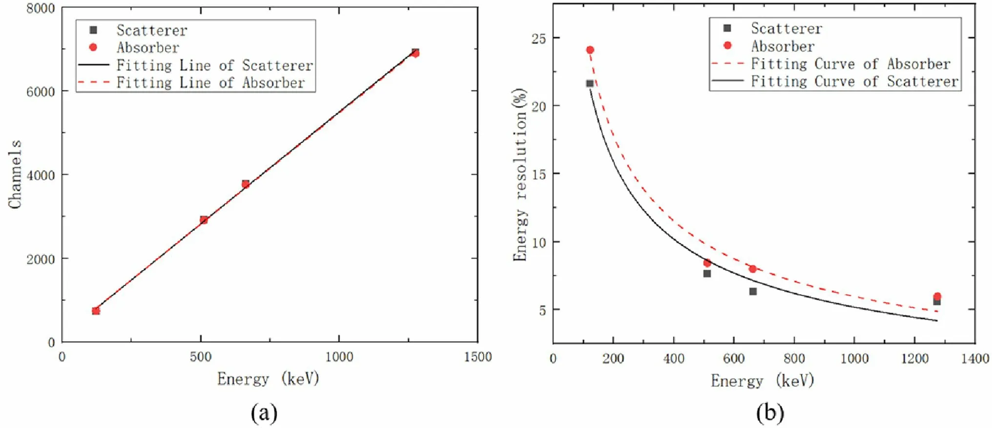
Fig.8 (Color online) Spectral performance of the scatterer and absorber measured using the prototype at four energies (122, 511, 662, and 1275 keV) of 22Na, 137Cs, and 57Co: a linear relationship between energies and channels; b measured energy resolutions and fitting curves

Fig.9 (Color online) Reconstruction results obtained with the point-like source placed at different lateral positions in the simulations: a joint two-dimensional images; b profiles along the x-axis; c FWHMs of the corresponding positions
Table 1 presents the trend of the angular resolution with respect to the distance between the source and the scatterer.The FWHM decreased as the distance increases but of which the downward trend becomes stable.Tables 2 and 3 present the angular resolutions of circular plane sources of different radii and the angular resolutions of point sources of different energies, respectively.As the radius of the source increased, the FWHM increased.Meanwhile, the FWHM decreased as the energy increased for both single-energy sources and multiple-energy sources.
8 Experiments

Fig.10 (Color online) Reconstruction results obtained with the point-like source placed at different positions along the diagonal of the FOV in the simulations: a joint two-dimensional images; b profiles along the diagonal line; c FWHMs of the corresponding positions

Fig.11 (Color online) Reconstruction results for the point-like source at three positions in the simulations

Table 1 FWHMs (degrees) for the reconstructed radioactive source (137Cs) at different distances (cm)

Table 2 FWHMs (degrees) for reconstructed radioactive sources (137Cs) of different radii (cm)

Table 3 FWHMs (degree) for reconstructed radioactive sources of different energies (keV) at 5 cm
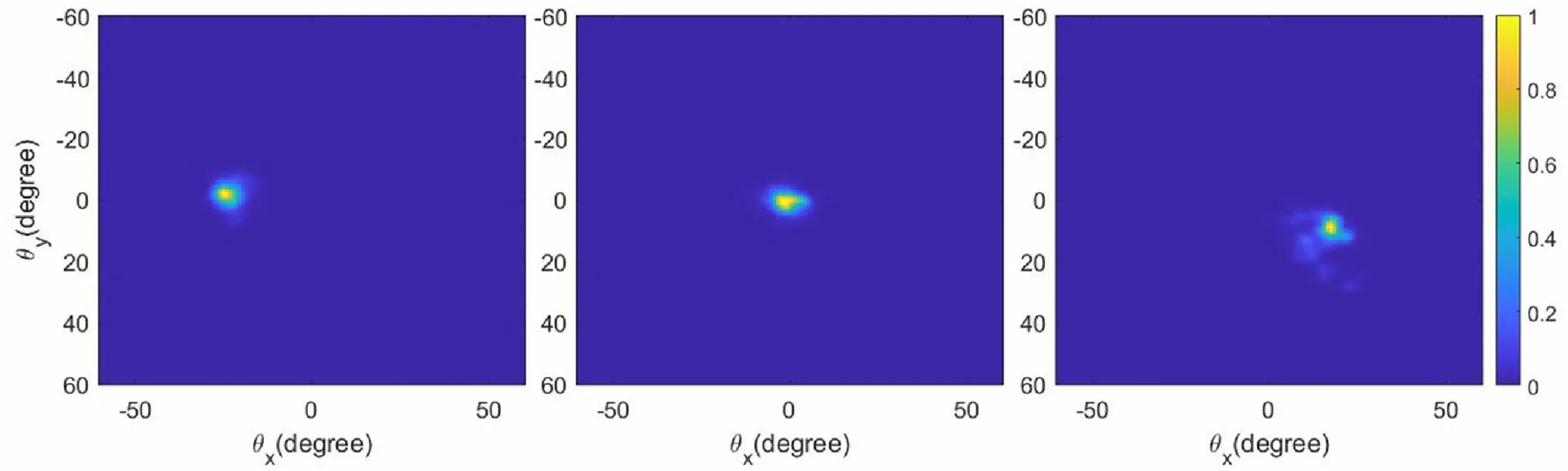
Fig.12 (Color online) Reconstruction results for the 137Cs point-like source with the fabricated LaBr3 CC prototype at three positions

Table 4 Deviations (degree) between the reconstruction positions and exact values in the experiments

Table 5 FWHMs (degree) of the reconstructed radioactive source at three different positions for the MC simulations and prototype experiments presented in Figs.11 and 12, respectively
As shown in Fig.12, the reconstruction results obtained using the LaBr3CC were consistent with the simulation results.Table 4 indicates that the deviations between the reconstruction positions and exact values in the three experiments were < 1.5°.Additionally, as shown in Table 5, the FWHMs of the reconstructed radioactive source at three different positions of the137Cs point-like source experiments agreed well with those of the corresponding simulations.The preliminary experimental results indicated that the angular resolution was approximately 6°.However, limited by the activity of the137Cs source and the measurement time, the number of coincidence events obtained in our experiments was only several hundred.Thus, the reconstruction image would have relatively large amounts of noise and artifacts owing to the small amount of projection data [33].As shown in the rightmost frame of Fig.12, which presents the source placed inPd2, because the sensitivity here was lower than that at the center of the FOV, the number of detected events was the smallest among the three positions.The deviation of the projection data, including the interaction positions and deposited energies, as well as the fewer statistics, led to reconstruction with more significant artifacts compared with the two other positions.
9 Discussion
In this study, we designed and developed a two-layer LaBr3-based CC with a large pixel size and evaluated the performance of our prototype through MC simulations and experiments.We used an LUT to acquire list-mode data and the SD-OE-RR algorithm to reconstruct images for evaluating the feasibility of the CC prototype.
To spatially cluster the energy-depositing events in the crystal unit, the Voronoi diagrams and LUTs were created.For each layer, 4-channel voltage signals representing the number of scintillation photons were output in every time window, and the locating method used in Anger cameras was used to decode the 4-channel data.Finally, we created a scatterplot of energy-depositing events.The centroids of the crystal units were selected to be the interaction positions of events decoded in the corresponding area in the scatterplot for achieving the optimal estimation.The Voronoi diagrams and LUTs were created for clustering events.In the Voronoi diagrams, the distance from any point in each separated area to the seed point in this area was the shortest among the distances to all the seed points,which was the principle we used to cluster events.We selected the most representative points in the bright points by seeking peaks in the processed scatterplots and created the Voronoi diagrams for both the scatterer and absorber.Then, the LUTs were created accordingly.However, the whole complex process was based on nonstandard scatterplots owing to the hardware and structure.We used a lightabsorbing material around the LaBr3crystal to differentiate the responses of the energy of edge pixels, resulting in a relatively low-voltage signal with high noise in the edge pixels (shown in Fig.7).The resistances in the encoding circuit had a deviation of approximately 1%, introducing a spatial error in the decoding process.Another defect was the incomplete correction for baseline drift of coding circuits, which caused an approximately 200-channel deviation in the voltage signals, affecting the decoding of both the position and energy.
The detection efficiency of the prototype for the137Cs point-like source used in our experiment was 1.67 × 10⁻³at 662 keV.Compared with the LaBr3-based CC developed by the IRIS group of MACACO, the energy resolution of our prototype was slightly lower.This may have been due to system defects of our CC.Because the LaBr3crystal deliquesces easily, we used a 1-mm-thick glass plate and a 1.2-mm-thick Al shell for the vacuum packaging of each layer.The glass plate behind the crystal would absorb part of the scintillating photons, and the Al shell surrounding the crystal would cause Compton scattering of the gamma photons; both effects would lead to an incorrect value of the deposited energy and reduce the energy resolution.Additionally, the minor background radiation of138La would influence the energy resolution [23, 34].However, the natural abundance of138La is approximately 0.09%, and it has a long half-life; thus, the influence of background radiation of138La would be negligible.Furthermore, the overall energy resolution of our prototype was the average of the energy resolutions of all the pixels in the detectors.The energy response of the edge pixels would reduce the overall energy resolution owing to the structure of our prototype, as mentioned previously.As shown in Fig.13, the best energy resolution of the LaBr3pixels in our CC was approximately 5% for 511-keV gamma rays, and the worst was approximately 15%.Thus,the overall energy resolution of the LaBr3CC developed in this study is worse than that achieved in a previous experiment involving an LaBr3scintillator detector (approximately 4%) [35] but comparable to the result of a simulation of a similar experimental situation [22].Another examplethe MACACO-is a similar LaBr3-based CC to ours but employs a whole LaBr3crystal and a 3-mm2SiPM array.Its angular resolution of approximately 5% was better than that of our CC owing to the advantages of its structure but was worse than that achieved in the previous experiment because the mutual decoding mode prevented it from achieving the ideal value.Although the energy resolution was affected by these system defects, our CC had a good energy resolution and is expected to achieve accurate nuclear material waste detection.In addition, if SiPMs larger than the scintillator array or one-to-one corresponding to the crystal array are used to reduce the loss of scintillation photons, the developed CC can achieve a better energy response of edge pixels.

Fig.13 (Color online) Energy resolutions of all the pixels in the developed LaBr3 CC prototype: a pixels in the scatterer; b pixels in the absorber
The reconstruction simulation results indicated that the angular resolution of our CC improved when the sources were moved away from the center of the FOV, indicating that a larger scattering angle corresponded to a better resolution [36].When the distances between the sources and the scatterer increased, the angular resolution improved, which was consistent with the results of a previous study [32].Two factors may have led to this phenomenon.First, the deviation of the scattering angle decreased as the distance increased,in accordance with Eq.(13).Second, the system was more satisfied with far-field conditions, improving the resolution.Moreover, the angular resolutions of point sources improved slightly as the energy increased owing to the better energy resolution of higher energies.The imaging performance for sources of multiple energies exhibited a similar trend to that for single-energy sources, and the excellent simulation results for a real point-like22Na (64.3% 511 keV and 35.7% 1275 keV) source indicated the applicability of the developed CC to nuclear decommissioning.The angular resolutions of circular plane sources worsened as the radii increased.For the point-like137Cs source, the reconstruction results of our experiments agreed well with the simulation results, as shown in Table 2.The average FWHM of the reconstructed source was approximately 6° in the experiments and 5.5° in the simulation.Additionally, there was a small deviation in the reconstruction positions.The imaging results for the prototype indicated that in our experimental condition, a high energy resolution led to good imaging performance even though the spatial resolution was low owing to the large pixel size.Compared with a previously reported LYSO CC prototype using the same reconstruction algorithm, the performance of the LaBr3CC was far better,even though the LYSO detectors had a small pixel size of 1 mm [17].Similarly, in Dennis et al.’s study, the effects of the energy resolution on the performance were more pronounced than those of the spatial resolution in the case where the detected gamma energy was < 2 MeV [37].The same trend was derived through a theoretical analysis using Eqs.(12) and (13).In our system, the radioactive source had a low energy of 662 keV-close to the static energy of the electron-which made thepart have a larger impact on the total deviation.Thus, when the CC is used for radioactive-material detection, improving the energy response may be more effective for enhancing the imaging performance than improving the geometric structure.In the case of a high energy resolution of the detector, a relatively loose restriction on the geometric structure to obtain a better sensitivity is allowed, as long as the CC system exhibited sufficient imaging performance for the expected applications.We investigated other CCs with large pixel sizes, such as a GAGG CC used in Fukushima to detect radioactive material [18, 19] and a CZT CC [38].The GAGG CC has similar geometric parameters to ours, but its results were significantly worse than those achieved in our experiments,mainly owing to the poor energy resolution of the GAGG scintillator.In contrast, the MLEM reconstruction results of the CZT CC, whose pixel size was even larger than that of our CC, were comparable to the results of our experiments.This first-ever practical verification demonstrated that the two-layer LaBr3-based CC with a large pixel size developed in the present study has a high angular resolution and good reconstruction performance, and it is expected to be used for radioactive source positioning in nuclear industry applications (e.g., nuclear decommissioning).Although its detection efficiency is relatively low, our prototype indicates that a thicker crystal array can be used in future CCs, and the LaBr3-based CC is also expected to be used in nuclear medical imaging.
In future research, we will further evaluate the performance of our prototype in actual usage scenarios through more detailed experiments and simulations-with a focus on applications in nuclear decommissioning, natural radioactive background monitoring, and nuclear medical imaging.We will also optimize the structure of our CC, e.g., improving the packing mode and reducing the pixel size, to improve the performance of our prototype.A better technique for locating the position of interaction is also under consideration.A bilayer SiPM can be used in each layer to obtain not only the lateral position but also more accurate depth information of the events.
10 Conclusion
We developed a two-layer LaBr3-based CC prototype with a large pixel size, along with a highly efficient technique for determining interaction positions by decoding 4-channel voltage signals and performing clustering using Voronoi diagram-based LUTs.On the basis of the calibration of the energy response of each crystal pixel, we provided a framework for obtaining list-mode data of two-point events.The results of experiments and simulations indicated the developed CC prototype achieved an angular resolution of approximately 6° for a137Cs point-like source at 5 cm and a detection efficiency of 1.67 × 10⁻³.The imaging performance of the developed prototype satisfies the requirements of radioactive source positioning in nuclear industry applications and the nuclear medical domain.
AcknowledgementsWe thank TOFTEK and Mr.Hu for assistance with the detector assembly and radioactive source experiments.
Author contributionsAll authors contributed to the study conception and design.Material preparation, data collection and analysis were performed by Ming-Hao Dong, Zhi-Yang Yao and Yong-Shun Xiao.The first draft of the manuscript was written by Ming-Hao Dong, and all authors commented on previous versions of the manuscript.All authors read and approved the final manuscript.
Data availabilityThe data that support the findings of this study are openly available in Science Data Bank at https:// www.doi.org/ 10.57760/ scien cedb.j00186.00137 and https:// cstr.cn/ 31253.11.scien cedb.j00186.00137.
Declarations
Conflict of interestThe authors declare that they have no competing interests.
杂志排行

Nuclear Science and Techniques的其它文章
- Measurement of the cavity-loaded quality factor in superconducting radio-frequency systems with mismatched source impedance
- Source-less density measurement using an adaptive neutron-induced gamma correction method
- Deep learning for estimation of Kirkpatrick-Baez mirror alignment errors
- Reference device for calibration of radon exhalation rate measuring instruments and its performance
- Fault locating for traveling-wave accelerators based on transmission line theory
- Establishment and study of a polarized X-ray radiation facility