Fault locating for traveling-wave accelerators based on transmission line theory
2023-09-18TongNingHuHaiMengWangYiFengZengHongJieXuLiChenGuangYaoFengYuanJiPei
Tong-Ning Hu · Hai-Meng Wang · Yi-Feng Zeng · Hong-Jie Xu · Li Chen · Guang-Yao Feng · Yuan-Ji Pei
Received: 9 December 2022 / Revised: 6 April 2023 / Accepted: 5 May 2023 / Published online: 17 August 2023
© The Author(s), under exclusive licence to China Science Publishing & Media Ltd.(Science Press), Shanghai Institute of Applied Physics, the Chinese Academy of Sciences, Chinese Nuclear Society 2023
Abstract Radio-frequency (RF) breakdown analysis and location are critical for successful development of high-gradient travelingwave (TW) accelerators, especially those expected to generate high-intensity, high-power beams.Compared with commonly used schemes involving dedicated devices or complicated techniques, a convenient approach for breakdown locating based on transmission line (TL) theory offers advantages in the typical constant-gradient TW-accelerating structure.To deliver such an approach, an equivalent TL model has been constructed to equate the TW-accelerating structure based on the fundamental theory of the TL transient response in the time domain.An equivalence relationship between the TW-accelerating structure and the TL model has been established via analytical derivations associated with grid charts and verified by TL circuit simulations.Furthermore, to validate the proposed fault-locating method in practical applications, an elaborate analysis via such a method has been conducted for the recoverable RF-breakdown phenomena observed at an existing prototype of a TW-accelerating-structure-based beam injector constructed at the Huazhong University of Science and Technology.In addition, further considerations and discussion for extending the applications of the proposed method have been given.This breakdown-locating approach involving the transient response in the framework of TL theory can be a conceivable supplement to existing methods, facilitating solution to construction problems at an affordable cost.
Keywords Traveling-wave structure · RF breakdown · Fault locating · Transmission line
1 Introduction
In recent years, with the development of high-power radiofrequency (RF) sources as well as microwave devices, rapid growth has been witnessed in high-gradient traveling-wave(TW) accelerators in support of various scientific applications [1-5], such as high-energy colliders, free electron lasers (FELs), and synchrotron radiation.However, for commercial and civil use, the accelerator facility is expected to be confined within a relatively small scale, which means the length of the TW structure should be reduced by further increasing the accelerating gradient [6].Furthermore, from the perspective of accelerator-based industrial applications,a high repetition rate and even continuous wave operations are required for generating high-intensity, high-power beams[7-9].In other words, adequate accelerating fields are supposed to be established in such TW structures by feeding a high RF power with a high work ratio.
However, after being fed into the accelerating structure, the RF power dissipates along its inner wall, and the associated pulsed RF heating, along with field emission,is considered to be a limiting factor in the design of roomtemperature high-gradient accelerators [10].Such pulsed heating induces not only cavity deformation but also vacuum arcing or breakdown [11, 12] becoming dramatically serious at high work ratios.Consequently, efforts have been made to analyze and reduce its influences [7, 13].Breakdown, which mainly depends on conductor materials, machining accuracy, and vacuum level, is one of the primary phenomena limiting the achievable accelerating gradient in normal-conducting RF structures [6, 12].To make the TW-accelerating structure suitable for normal operations, a process of gradually increasing fed-in power,namely RF conditioning, is commonly deployed after a long period of vacuuming [14, 15].Most of the breakdowns caused by gas ionization and machining burrs can be avoided by sufficient RF conditioning under the conditions of both low and high power.However, in the case of high gradient or high work ratio, there will still be occasional ignition, which might affect the normal operation of the accelerator and even cause permanent damage to the RF structure, while associated reflection power might destroy the microwave device or even the RF source [16].Therefore, it is vital to find the breakdown position and analyze the cause, thereby maintaining beam quality and ensuring machine safety but also helping us to understand the underlying physics of TW accelerator.This will then drive continuing interest in further improvement in cases of higher gradient and higher power and even guide the in-depth development of X-band and higher frequency TW accelerators [17, 18].
Extensive efforts especially over the past decade, involving both simulations and experiments, have been made to identify and analyze the formation mechanism and underlying physics of RF breakdown [19-22].Many works have contributed greatly to the in-depth study of RF breakdown physics and the improvement of accelerator facilities[23-26].Because the experimental results are significant for evaluating the simulation models and improving practical engineering, a considerable number of dedicated devices and techniques have been developed to conduct online diagnostics of RF breakdowns [27-31].Unfortunately, most of them are inevitably accompanied by complex peripheral subsystems, which lead to an enlarged facility scale as well as extra economic costs, not to mention other costs of necessary upgrades for existing facilities.However, for constructed accelerators, if the breakdown is recoverable and does not cause permanent damage, compared to disassembling the facility, it is preferred to analyze the phenomenon and identify the cause online, bringing commensurate cost savings.One attractive approach is employing predictive methods to limit the impact of the breakdowns [6, 32], such as using data-driven machine learning algorithms, which have been recently applied for design, commissioning, and diagnosis in the accelerator field [33-36].Nevertheless, such machine learning-based predictions require a considerable volume of data to form the training set.Therefore, it is imperative to seek a more convenient and cost-efficient approach with the lowest possible cost to analyze and locate RF breakdowns in TW-accelerating structures.
According to the fundamental theory upon which TW accelerators are based, the entire TW-accelerating structure can be regarded as a transmission line (TL) with accelerating voltage traveling at group speed, while the voltage presents as a TW.Therefore, it is logical to introduce fault-locating methods based on the TL theory used in power and signal systems [37-40].This context concentrates on investigating an equivalence relation between the TW-accelerating structure and the TL by recalling the fundamental TL theory and exploring how to apply the TL-based fault-locating method to the TW-accelerating structure.In this method, circuit simulations are conducted and analytical derivations associated with grid charts are formulated.In addition, the RF breakdown phenomena, which have been observed at a prototype of an TW-accelerating-structure-based injector constructed at the Huazhong University of Science and Technology (HUST injector) [41, 42], are reviewed and taken as an example for validating the proposed method.Moreover, we also discuss how to further extend the proposed approach.
2 Fault-locating method based on TL theory
As mentioned in Sect.1, the approaches based on TW and TL theories are commonly applied for fault locating in both power and signal systems.Among such approaches, the pulse-reflection method is widely used in TLs owing to its simplicity and low cost [43, 44].In this method, a voltage pulse is applied to the faulty line and traverses as a TW therein.When it arrives at the fault point, both reflection and transmission phenomena will occur at the same time.Then, by measuring and analyzing the voltage waveform at the initial terminal of the TL, the location of the fault point can be determined.Nevertheless, when the TL is very short, even the wave propagation time is close to the applied pulse width, and overlap of incident and reflected pulses will inevitably occur at the line.It thus becomes necessary to shorten the pulse.However, the high-frequency components of such short pulses will be lost, and the voltage waveform will be distorted as it traverses the line, which might cause information loss and a reduction in the accuracy of fault locating [43].
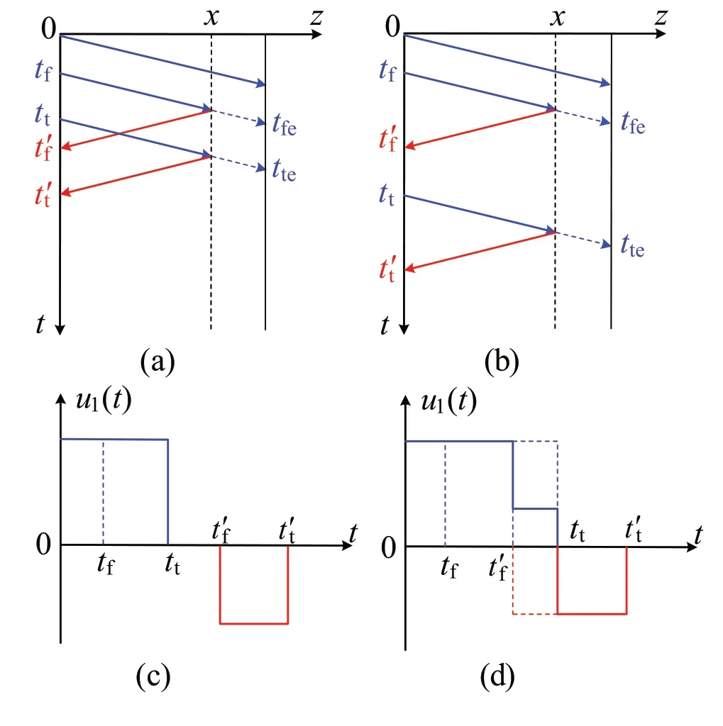
Fig.1 Schematics of the pulse-reflection method applied in faulty TLs: wave processes via grid charts under (a) a short pulse and (b) a long pulse; voltage waveforms at the initial terminal under (c) a short pulse and (d) a long pulse

To clearly explain the fundamental principle of the pulsereflection method, grid charts are introduced here to intuitively illustrate the transmission and reflection processes of the TW in the faulty TL.For the sake of simplification,multireflections are not considered by assuming that both terminals of the line are always matched.For a specific TL with a fixed fault point, according to different widths of the incident pulse, there might be two different kinds of voltage waveforms at the initial terminal.These correspond to short-pulse and the long-pulse cases, with the wave processes being illustrated by the grid charts in Fig.1a and b,edgettwould be later thant′f, in which case the waveform observed at the initial terminal looks like that in Fig.1d, and there is an overlap between the incident and reflected pulses.respectively.In the figure, the horizontal axis represents the longitudinal location on the TL of lengthl, with the starting point set toz=0 and the fault point atz=x.The vertical axis represents the times at different longitudinal locations.As shown in Fig.1a and b, the incident pulse is input to the initial terminal at timet=0 , and when its front edge reaches the positionz=x, a fault occurs after a cumulative timetf.Then, both transmission and reflection will occur atz=x,and the front edge of the reflected pulse will arrive at the initial terminal att=In addition, it is noteworthy that, for the TW-accelerating structure, RF breakdown will cause the local vacuum to deteriorate at the fault location, resulting in a lower breakdown threshold, which in turn leads to continuous discharge for the duration of the RF pulse.Therefore, only when the incident power is turned offwill the surface electric field required for breakdown generation disappear, and then the vacuum can be slowly recovered.That is, once the breakdown occurs, the fault cannot be recovered within the RF pulse duration.The corresponding wave process is exactly the same as that in the faulty TL, as demonstrated in Fig.1b.
For the short pulse, the emitted time of its trailing edge,tt,would be earlier than the arrival time of the front edge of the reflected pulse,t′f.The voltage waveform established at the initial terminal can be represented as two separated pulses with opposite amplitudes, as plotted in Fig.1c, and both of them have the same width as the initial incident pulse.In contrast, for the long pulse, the emitted time of its trailing
wherevis the wave velocity in the TL.Note that, in the long-pulse case, because of the inevitable overlap between the incident and reflection waves, the negative pulse in the waveform at the initial terminal will be shortened, while an amplitude step will appear in the positive pulse.Moreover,when the fault point is a short-circuit fault and total reflection is generated, the voltage waveform at the initial terminal also appears as two separated inverse pulses, but the width of the positive pulse is smaller than that of the original incident pulse, enabling it to be distinguished from the short-pulse case.Therefore, before applying such a pulse-reflection method for fault locating, it is necessary to first judge the application case according to the width and amplitude of the positive pulse caught by the oscilloscope at, and then identify the trailing edges of the positive and negative pulses from the observed waveform.Finally, Eq.(1) can be used to solve for the fault distance.Note that, when the terminals of the TL are not matched, multiple reflections will occur in the TL, which is a complex problem and is beyond the scope of this study.
3 Applying the pulse-reflection method to a TW-accelerating structure
3.1 General description
According to the basic theory of RF accelerators, in the constant-gradient TW-accelerating tube with a constant phase velocity, the accelerating voltage established by fed-in RF power is invariant along the longitudinal position.Although the dissipated power values in the individual cells are different from each other, from the view of the amplitude of the accelerating voltage, it is conceivable to regard the entire structure as a lossless TL.Furthermore, because the RF signal fed into the accelerator is modulated by a square wave,the excitation source can also be equivalent to the square wave by ignoring the inner RF oscillation.Therefore, by using the transient response of the TL described in Sect.2 and analyzing the delay time between the wave edges, the fault location inside the TW-accelerating structure can be determined.
In a lossless TL, the wave velocity should correspond to the group velocity of the TW-accelerating structure.The latter directly relates to the time it takes to establish the field,namely the filling time of the TW-accelerating structure,which is also the arrival time of the front edge of the square wave propagating in the TL.However, the group velocity varies for each cell of the TW structure, which means that the equivalent TL is nonuniform.However, as a constantphase and constant-gradient structure, each cell of the TWaccelerating structure has the same lengthLc, and the group velocity of each cell decreases monotonically along the longitudinal position.Consequently, it is conceivable to make each cell of the TW-accelerating structure be equivalent to a segment of the TL.Figure 2a shows the group velocity distribution of a classical SLAC-like TW-accelerating structure.The wave velocity of theith segment equals the group velocity of theith cell, defined byvgi.Therefore, the final wave velocity will be a comprehensive result of multiple different velocitiesvgi.The grid chart shown in Fig.2b demonstrates such an equivalent effect.
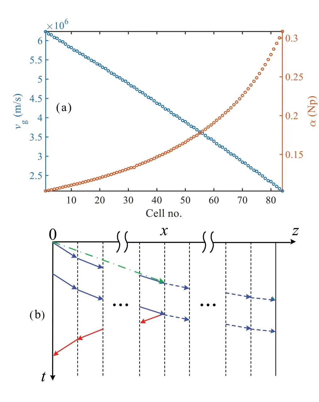
Fig.2 (Color online) a Group velocity and attenuation factor distributions of the 3-m SLAC TW-accelerating structure.b Wave process in its equivalent TL model
As can be seen from Fig.2b, although the wave velocitiesvgiof the segments are different from each other, the broken lines are monotonic.Therefore, under the condition that the wave propagation distance and time are fixed, the broken line representing the wave process in the multisegment TL can be connected end to end (as shown by the green dashed-dotted line), and its slope corresponds to the overall wave velocity.Then, if the fault occurs in theNth segment,the round-trip time of the TW front edge between the initial terminal and the fault point is
whereLxis the distance between the upper end and the specific fault position inside theNxth segment, which denotes the exact fault location inside the fault segment.Obviously,because there are two variablesNandLxto solve for, it is inconvenient to directly solve Eq.(2) only from the knownvgiandLc, as well as the measuredtx.Nevertheless, the round-trip time of the wave from the initial terminal of the entire TL to the lower end of each segmentNcan be calculated in turn to construct a data table.The number of the fault segment can then be determined by consulting the data table.Finally,Lxcan be solved by substituting the known quantitiesvgi,Lc,tx, andNinto Eq.(2).
3.2 Simulation verification using the TL model
As analyzed in the previous subsection, the constant-gradient TW-accelerating structure can be equivalent to a whole TL consisting of a cascade of uniform segments with different wave velocities.The RF breakdown occurring in the TW-accelerating structure then corresponds to a lowresistance or short-circuit fault in the TL.Moreover, it is feasible to adopt a delay switch to the fault resistance to simulate the start time of the RF breakdown.The corresponding equivalence relationships of the main parameters are listed in Table 1.
To verify such equivalence, simulations were conducted in MATLAB Simulink by constructing a distributed-parameter circuit with a cascade of uniform lossless TL segments,as shown in Fig.3a.For the sake of consistency, both terminals of the entire TL are matched in the simulation model,and the velocity and propagation time for each segment areequal to those of the SLAC TW-accelerating structure mentioned in the previous subsection.Because each segment is uniform and lossless, for all the segments, both the resistance and the leakage conductance per unit length can be set to zero, while the inductance and the capacitance per unit length of theith segment,LiandCi, need be set under the constraint of
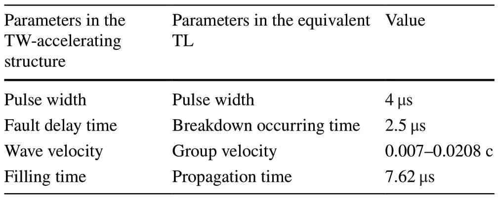
Table 1 Equivalence between the TW-accelerating structure and the TL

Fig.3 a Simulation model of a multisegment TL.b Simulated voltage waveform at the initial terminal
Moreover,LiandCishould also be specially set to avoid inner multireflection in the simulation model.Given a pulse with a high voltage of 400 V being sent from the source and a low resistance occurring in the 21st segment after a delay time of 2.5 μs from the front edge of the pulse, the voltage waveform as shown in Fig.3b can be observed after the reflected wave reaches the initial terminal.
The simulated waveform given in Fig.3b is consistent with the schematic graph shown in Fig.1d.Therefore,according to the basic theory of the pulse-reflection method introduced in Sect.2, as well as the equivalence relationship derived in Sect.3.1, after identifying the trailing edges and measuring their time difference, the fault location can be determined from Eq.(2).By substituting the simulation results, the fault location can then be judged to be the 21st segment, which is consistent with the initial setup.
Note that the delay time when the fault occurs is useless in the fault-locating method.In addition, it is worth noting that, by using a long TL model with an overall velocity corresponding to that in Fig.2b, the same voltage waveform can be obtained at the initial terminal, which can further verify the underlying logic of the equivalences between the TW-accelerating structure and the TL model and validate the feasibility of the fault-locating method proposed in this context.
4 Application of the pulse-reflection method for the HUST injector
As mentioned in the previous section, under reasonable equivalences, the pulse-reflection method can be applied to locate the RF breakdown in the TW-accelerating structure.To further verify such an approach, analysis of the RF breakdown has been performed at the HUST beam injector by using the theoretical framework proposed above.
4.1 Brief introduction to the HUST injector
As reported in previous publications [38, 39, 47, 48], HUST THz-FEL is proposed to generate high-power, continuously tunable THz radiation, while the beam injector needs have the ability to provide high-performance driven beams that are comparable to photocathode injectors.However, because the HUST THz-FEL is intended for industrial and commercial use, both the injector and the entire facility must be confined within an acceptable scale.Consequently, an ITCbased pre-injector has been adopted in the constructed prototype of the HUST injector.Moreover, a SLAC-like constantgradient TW-accelerating structure with 23 cells has been installed downstream to boost the beam energy to 14 MeV.In addition, for facility compactness and cost efficiency,dedicated insertion devices for beam diagnosis, which might involve complex peripheral subsystem, are avoided in the prototype.Therefore, efforts have been made to conduct indirect estimations for the beam properties under the existing conditions based on underlying accelerator physics.
Nevertheless, for necessary measurements, two fast current transformers (FCTs) were exploited to measure macropulse currents upstream and downstream of the TW-accelerating structure, as illustrated by Fig.4a.Meanwhile, a directional coupler, which is utilized to measure forward and reverse RF powers, has been installed on the waveguide connected to the TW-accelerating structure for feeding the RF power.It is worth mentioning that, as illustrated by Fig.4b,coaxial absorbing loads were applied at the last four cells of the TW-accelerating structure instead of a traditional output RF coupler, while previous research indicated that the structure can achieve a more compact layout as well as more symmetric accelerating fields.However, to absorb residual power at the end of the TW-accelerating structure, the coaxial loads must be able to withstand high dissipated power and be able transfer it to a thermal loss.The corresponding thermal analysis is shown in Fig.4c.

Fig.4 (Color online) a Sketch of the TW-accelerating structure with measurement equipment installed on the HUST injector.b Structure sketch of the absorbing loads.c Thermal calculation result of the last four cells of the TW-accelerating structure
After adequate RF conditioning, the TW-accelerating structure at the HUST injector worked normally for several months.However, after a subsequent replacement of an invacuum device, RF breakdown has been observed again after a fast increase of modulator voltage during a relaunched process of RF conditioning, and such a phenomenon also appears at a high repetition of the RF power.Given that sufficient RF conditioning has been conducted before and that the RF breakdown is repeatable, which means that no permanent damage has been caused in the TW tube, it was preliminarily determined that this phenomenon is related to the absorbing loads at the end of the TW-accelerating structure.These may adsorb a large amount of gas when destroying the vacuum, but the gas released at low power is limited, and the downstream vacuum pump cannot pump fast enough.As a result, when the thermal load increases, the gas released therein has no time to be removed and thus generates ionization ignition under the high-gradient RF field.However, once the power is reduced, the TW-accelerating structure can be restored to normal operation.
Based on the above analysis, the downstream pump of the TW accelerator with a speed of 50 L/s has been replaced by a new pump with the speed of 100 L/s.In the process of subsequent vacuuming and RF conditioning, the gas adsorbed in the collinear load was almost fully released, and the gasexcited occasional ignition was quickly pumped away by the high-speed pump.After over 70 days, according to statistical results, the breakdown rate was reduced from 50 times/h to 1 time/h under the same conditions.Moreover, after sufficient conditioning and vacuuming over a year, the amount of gas molecules adsorbed by the collinear load were greatly reduced, and, in subsequent operation, such breakdowns did not occur again.The validates the reasonableness of the preliminary judgment.A more detailed analysis will be given in the following subsections.
4.2 Preliminary analysis of RF breakdown at the HUST injector
To clarify the above fault judgment, both the beam and RF signals, which were recorded at the same time as the RF breakdown occurred, are analyzed here.
As can be seen from Fig.5a, when RF breakdown occurs,electron beams can be detected by the two FCTs installed upstream (the cyan curves, namely, FCT1) and downstream(the magenta curves, namely, FCT2) of the TW-accelerating structure.Note that the amplitudes of the two beam signals are opposite.This is because both originated from the ignition beam at the fault location but were accelerated and emitted toward two opposite directions.In other words, two standing-wave accelerating fields, which are isolated by the fault point, are established in the TW-accelerating structure.Although there is no power detector settled downstream of the TW-accelerating structure, RF signals detected upstream shown in Fig.5b (the magenta curves, namely, Acc-) demonstrate that the reflected power is no longer zero, which proves the establishment of the standing-wave field between the entrance and the fault location of the TW-accelerating structure.
Furthermore, by opening the persistence displaying mode of the oscilloscope, one can conveniently observe the dynamic change process of the reflected signal with time.As recorded by Acc- in Fig.5b, after the first reflected power pulse (labeled 1st) caused by the first RF breakdown, the reflected pulse will be observed with each subsequent incident RF pulse and ignition beam.To demonstrate this more clearly, the subsequent reflected pulses are successively labeled 2nd, 3rd, 4th, and 5thin Fig.5b.Moreover, the front edge of the reflected pulse moves forward step by step, while the trailing edge almost remains in the same position.The latter phenomenon indicates that RF breakdown occurs at the same location in the TW-accelerating structure.The variation of the front edge indicates that, during the duration of the RF macropulse, the starting time of breakdown gradually advanced,because the vacuum deterioration caused by the previous breakdown facilitates subsequent breakdowns, making them earlier every time.

Fig.5 (Color online) a Beam signals when RF breakdown occurs(where Mod is the voltage signal of the modulator, Kly is the reflected power signal detected at the klystron, and FCT1 and FCT2 denote the beam currents upstream and downstream of the TW structure, respectively).b RF power signals when RF breakdown occurs(where Pre+ is the power signal injected into the pre-bunching cavity installed upstream of the TW structure, Kly+ is the forward power signal detected at the klystron, and Acc+ and Acc- denote the forward and reflected power signals, respectively)
Note that because the detected power pulses on the oscilloscope come from the RF voltage signals output by the directional coupler after square-law detection, they are proportional to the power amplitudes.Figure 5b shows that the forward power (the cyan curves, namely, Acc+)detected by the directional coupler increases when breakdown occurs, and the duration of the increased portion is the same as that of the reflected pulse.This indicates that the directional coupler is no longer matched after breakdown, resulting in the reflected voltage being reflected again here and superimposed on the detected forward voltage pulse, thus forming an increase in the forward power amplitude.
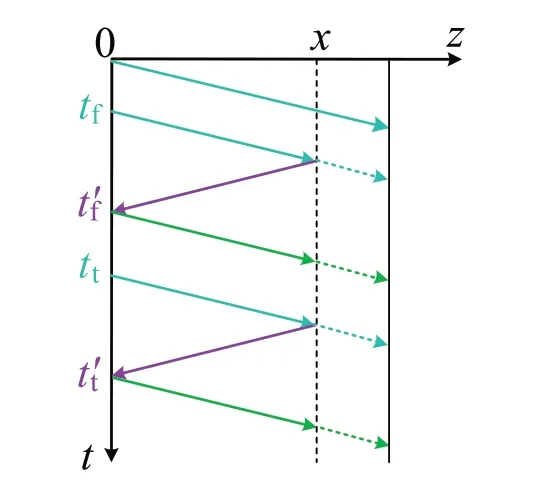
Fig.6 Wave process in the TW-accelerating structure at the HUST injector
4.3 Fault locating for the HUST injector
As mentioned in Sect.4.2, both reflection and transmission will occur at the breakdown position.Meanwhile, because the absorbing loads are applied at the end of the TW-accelerating structure instead of a traditional output coupler, the residual power will be completely absorbed; thus, the final terminal is always matched and there is no reflection.Therefore, according to the TL theory introduced in the previous sections, the grid chart describing the wave process after breakdown for the TW-accelerating structure at the HUST injector can be plotted (Fig.6).In the figure, the green solid lines represent the reflections at the detecting point; given their limited amplitude contributions, which cannot be displayed by the oscilloscope, further multireflections at the fault point can be ignored for simplification.Furthermore,because the directional coupler has been installed on the short waveguide connected to the first cell of the TW-accelerating structure, and the wave speed therein equals that of light, the initial terminal was assumed to be combined with the detecting point in the equivalent TL.
Given the wave process analyzed above, and by considering the characteristics of the directional coupler, the voltage amplitudes established at its two ports can be identified, as illustrated in Fig.7a and b.As mentioned in the previous subsection, the reflection wave will contribute to the detected forward voltage, and steps can be observed in Fig.7a.Meanwhile, because the established voltage at the initial terminal will compensate for the reverse voltage wave, the voltage amplitude detected at the reverse port of the directional coupler should have the pattern shown in Fig.7b.In addition,because two square-law detectors were adopted to detect the signals, closer representations of the actual waveforms on the oscilloscope are shown in Fig.7c and d.To be consistent with Fig.5b, the waveform schematics are plotted inversely.Note that only the delay times of relative macro-pulses in the detected waveforms need be addressed according to Eq.(2), and the transmission and reflection coefficients are also unknown.Consequently, the voltage waveforms plotted in Fig.7 are only schematic diagrams, and their amplitudes do not represent the real values.

Fig.7 Schematics of waveforms at the entrance of the TW-accelerating structure: a forward voltage, b reverse voltage, c forward power,and d reverse power
5 Further considerations and discussion
In this section, we further apply TL theory to the TWaccelerating structure and discuss how to extend the proposed time-based fault-locating method.

5.1 Discussion of more general situations
As mentioned in Sect.3, the amplitude of the accelerating voltage is constant in the TW-accelerating structure,but the power actually attenuates along the cell number to build the accelerating field.Corresponding attenuation factors are determined by the accelerating structure and do not vary with the incident power, and Fig.2 also gives the attenuation factor distribution of the SLAC TW-accelerating structure.In other words, the constant-gradient constant-phase-velocity TW-accelerating structure can be equaled to a uniform lossless multisegment TL with different wave velocities for each segment.
However, for industrial accelerators, both the phase velocity and gradient are generally not constant.To achieve a high capture rate, the phase velocity is generally increased cell by cell and then stabilized around the speed of light, and the corresponding accelerating gradient also has the same distribution trend.Nevertheless, after each cell is filled by the accelerating field, it can still be regarded as a uniform lossless TL segment,while the unequal gradient will only affect the voltage amplitude observed at the initial terminal.Because the proposed fault-locating method relies only on the trailing edge distance of the RF pulse signals rather than their amplitudes, it is feasible to extend the application of the proposed method to nonuniform TW accelerators under known structure parameters.
To verify such an extension, an industrial accelerator with a nonuniform TW structure was considered [50].The distributions of the phase velocityβpand accelerating gradientEmalong the cell number are illustrated in Fig.8a.To improve the capture rate to >90% , bothβpandEmwere designed to grow monotonically with cell number for the first 25 cells, and the latter stabilized at ~ 19 MV/m for the last few cells, while the former returned to light speed.By utilizing the same analysis as in Sect.3, an equivalent TL model with different segments has been constructed for a nonuniform TW accelerator.

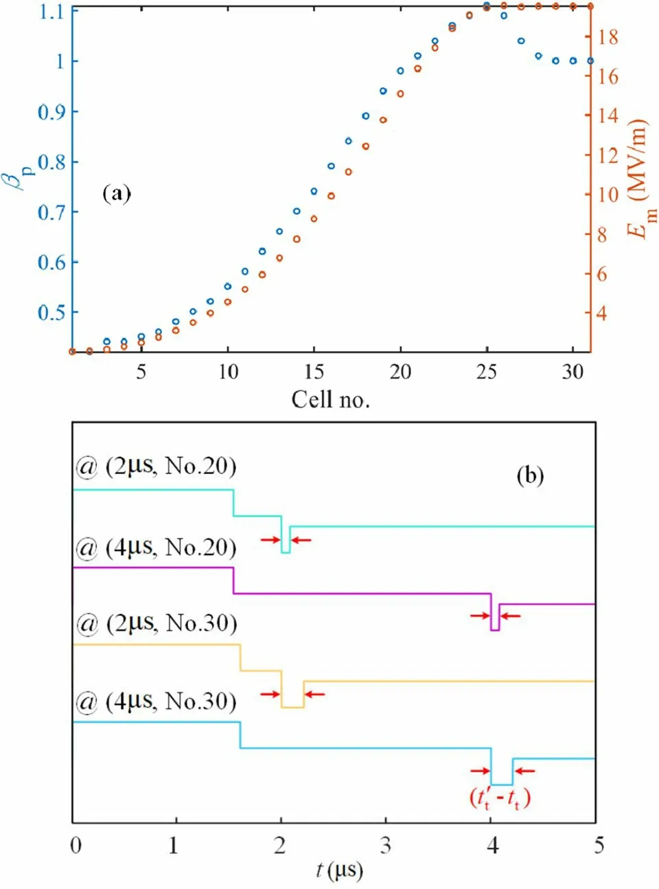
Fig.8 (Color online) a Phase velocity and accelerating gradient distributions of the nonuniform TW accelerator.b Voltage waveforms at the initial terminal with different settings of stimulating pulse width and a faulty segment
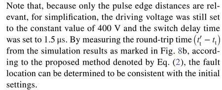
In essence, the pulse-refection method makes use of the transient response in the time domain of the TL under the excitation of a rectangular pulse, and it uses the reflection delay time from the fault point combined with the equivalent wave speed to deduce the fault location.The proposed approach does not involve pulse amplitudes, which indicates that it can be extended to nonuniform TW-accelerating structures as well.Consequently, if only the length of each cell in the TW accelerator and the corresponding group velocity are known, the approach relevant to Eq.(2)can always be applied to obtain the fault position information.In other words, the fault-locating method proposed in this context can be extended to more general cases of TW accelerators.
5.2 Improved locating method for a constant-impedance TW accelerator
Furthermore, for a constant-impedance accelerator with an uncertain group velocity, a more convenient fault-locating method can be obtained by combining the equivalent TL theory.Because the group velocity is constant, Fig.1b can be recalled here to develop the following improvement: As marked in the figure,tfeandttedenote the arrival times of the front and trailing edges, respectively, at the exit of the accelerator.For a TW-accelerating structure with a length ofl, RF detectors can be conventionally installed on both the input and output couplers, and so it is reasonable to assume thattfeandttecan be measured online.Similar to the deduction of Eq.(1), fault location can be obtained based on the detected delay time of the pulse at the exit of the tube:

Finally, for the constant-impedance TW-accelerating structure, the RF breakdown location can be determined without needing to know the group velocity.Because the directional couplers for RF detection are conventionally installed at both the entrance and exit of the tube, the improved approach denoted by Eq.(5) is quite practical.
6 Conclusion
An economically convenient method for breakdown analysis and location identification in TW-accelerating structure was introduced on the basis of TL theory.By recalling the fundamental theory of the TL transient response in the time domain, the equivalence relation between the TWaccelerating structure and the TL was established first.Analytical derivations for the fault-locating method in the TL were demonstrated by using grid charts, and the equivalent circuit simulations were performed to verify the analysis by taking the classical SLAC TW-accelerating structure as an example.Both the theoretical and simulation results indicated that it is reasonable to equate the constant-gradient TW-accelerating structure as a whole TL composed of multiple segments of uniform lossless TLs and that the accelerating voltage in the structure can be regarded as a TW traversing with a series of group velocities in the multisegment TL.
Furthermore, after elaborately analyzing the recoverable RF breakdown phenomena observed before, the proposed fault-locating method was applied to the HUST injector to find the breakdown position in the TW-accelerating structure.Combined with the experimental data as well as the adopted solution at that time, the following conclusions can be made: The fault location obtained via the proposed TLbased approach is feasible and consistent with the previous experimental judgement.In addition, by analyzing the characteristics of the time-based fault-locating method, further considerations involving more general TW accelerators were investigated to extend the applications of the proposed method.The corresponding analyses were also verified by using circuit simulations.Moreover, for another typical TWaccelerating structure with a constant-impedance structure,an improvement for the TL-based locating method was explored and discussed preliminarily.
Consequently, the TL-based fault-locating approach,namely the pulse-reflection method, proposed in this context can deliver the RF breakdown location for TW-accelerating structures without dedicated devices or complicated techniques.This provides a conceivable supplement to existing approaches for RF breakdown analysis.This potentially enables achieving a solution for faulty accelerators at the lowest possible cost, while the proposed TL-based fault-locating method can also be broadened to other TW-accelerating structures in the future.
AcknowledgementsThe authors thank Prof.Ping Tan for her stimulating discussions about microwave technology.
Author contributionsAll authors contributed to the study conception and design.Material preparation, data collection and analysis were performed by Tong-Ning Hu, Hai-Meng Wang and Yi-Feng Zeng.The first draft of the manuscript was written by Tong-Ning Hu and Hai-Meng Wang, and all authors commented on previous versions of the manuscript.All authors read and approved the final manuscript.
Data availability statementThe data that support the findings of this study are openly available in Science Data Bank at https:// doi.org/ 10.57760/ scien cedb.j00186.00006 and https:// doi.org/ 10.57760/ scien cedb.j00186.00006.
Declarations
Conflict of interestThe authors declare that they have no competing interests.
杂志排行
Nuclear Science and Techniques的其它文章
- Measurement of the cavity-loaded quality factor in superconducting radio-frequency systems with mismatched source impedance
- Source-less density measurement using an adaptive neutron-induced gamma correction method
- Deep learning for estimation of Kirkpatrick-Baez mirror alignment errors
- Reference device for calibration of radon exhalation rate measuring instruments and its performance
- Establishment and study of a polarized X-ray radiation facility
- Development and preliminary results of a large-pixel two-layer LaBr3 Compton camera prototype
