Sealing performance and mechanical response of mud pump piston
2023-08-30JieZhangWenjieJiangPaiZhuTingZheng
Jie Zhang ,Wenjie Jiang ,Pai Zhu ,Ting Zheng
a School of Mechatronic Engineering,Southwest Petroleum University,Chengdu,610500,China
b Oil and Gas Equipment Technology Sharing and Service Platform of Sichuan Province,Chengdu,610500,China
c Luzhou Vocational and Technical College,Luzhou,646000,China
Keywords:Piston cup Sealing performance Mechanical property Groove structure
ABSTRACT In order to explore the effect of piston cup structure on its sealing characteristics and mechanical properties,a numerical simulation model of the piston cup in the BW-160 mud pump was established.Effects of work load,friction coefficient and cup structure parameters on the sealing and mechanical properties of the piston were discussed under mud discharge condition.The results show that stress concentration on the root and lips of the cup is becoming more and more obvious with the working load increases.The average contact pressure increases with the friction coefficient increases,but an excessive friction coefficient accelerate the wear of the cup and the heat generation.Effect of the piston lip interference and thickness on the sealing performance of the cup is greater than that of the inner wall width.The piston with groove structure can effectively improve the sealing performance of the piston.The mechanical properties of triangular groove cup are better than that of semicircular and trapezoidal groove cup.
1.Introduction
Mud pump is the main equipment of mud circulation system in engineering construction,which has the functions of cooling bit,carrying bottom hole cuttings and assisting drilling.The rubber cup on the piston of mud pump is the key part of sealing system.Its sealing performance directly affects the efficiency of mud pump and the whole drilling process.The average service life of the piston cup is the shortest according to investigation of the vulnerable parts of the mud pump [1],which is the weakest link in the mud pump.The failure of the piston cup is mainly due to the wear marks on the sealing surface of the cup due to abrasive wear,then resulting in tiny mud leakage.With the wear marks continue to expand,piston failure appears [2].
In the actual working conditions,improving the material and shape of rubber leather cup is a common method to prevent premature failure of the leather cup.Some researchers have developed the piston cup of reverse mud pump with new elastic materials,which has increased the service life of the piston by 8-10 times[3].Some company have developed a combined piston suitable for high pressure by using polyurethane with low hardness as the outer ring of piston cup and polyurethane with high hardness as the inner ring of piston cup[4].In recent years,the use of modified materials such as glass fiber graphite [5] has greatly improved the comprehensive performance and anti-friction and wear resistance of the piston.Wang [6] explored the design idea of using Sialon ceramic material as the mud pump cylinder liner.Wang[7]used rubber and composite materials as the root reinforcement layer to improve the pressure resistance and wear resistance of the piston.X-R piston was developed by Southwest Petroleum Institute and Inner Mongolia Arongqi Rubber Factory[8],a solid lubricant was sued to improve the wear resistance,and a nylon ring was used at the root to center to avoid eccentric wear.Etsion[9,10]studied various nonsmooth texture surfaces and found that the surface with microporous arrays has a better lubrication performance than the smooth surface.Wu[11]studied internal combustion engine pistons with a bionic pit-shaped structure and found that the bionic pit structure has a good heat dissipation and wear resistance.Sun [12] studied the wear-resistant mechanism of bionic pit piston and optimized the pit structure.At present,there are few studies on the influence of load conditions and structural parameters on the contact mechanical properties of the cup,which can help design a better piston cup.Therefore,influence of load,friction coefficient and cup structural parameters on the performance of BW-160 mud pump piston were investigated.
2.Numerical calculation model
The mud pump piston and cylinder liner friction pair is in a very complicated environment under actual working conditions.Therefore,several assumptions were made when establishing the numerical simulation model [13]:
(1) The friction pair of the piston and cylinder liner is an ideal axisymmetric model.
(2) The materials used in the piston and cylinder liners and other parts are uniform,continuous and isotropic.
(3) The entire piston cup is made of polyurethane rubber.
BW-160 three-cylinder single-acting pump piston is chosen as the research object.The inner diameter of cylinder liner is 70 mm,the minimum outer diameter of the piston cup is 70 mm,the maximum outer diameter is 71 mm.Which means that the interference of the piston is 0.5 mm.The length from the lip to the root of the bowl is 30 mm.The steel core and cylinder liner material is 45#,its elastic modulus is 210 GPa,Poisson's ratio is 0.3,and the density is 7800 kg/m3.The piston cup is made of polyurethane rubber.In the simulation,Mooney-Rivlin model[14,15]is used,C10is 2.5 MPa,C01is 0.625 MPa,and the density is 1120 kg/m3.The finite element model is shown in Fig.1.

Fig.1.Piston model of mud pump in engineering construction.
3.Influence of parameters
3.1.Force of mud pump piston
As shown in Fig.1,the cup tends to squeeze out when the piston completes the action of sucking mud,the piston moves to the left.It completes the action of discharging mud and the leather cup is squeezed inward,when the piston moves to the right.Fig.2 is the force diagram of the rubber cup,figure (a) represents the force of the cup in the process of sucking mud,the figure(b)represents the force in the process of mud discharge,and the figure(c)is the force of the rubber cup size parameters.The force of the rubber cup includes the squeezing force of the steel core and the cylinder liner against the cup,the pressure of the mud,and the friction when the mud is sucked or discharged.The factors that affect the working performance of the rubber piston include the actual working loadp,the friction coefficient α on the contact surface,the widthaof the cup's inner wall,the lengthlof the cup's sealing surface,the interferencehand the thicknesscof the cup.
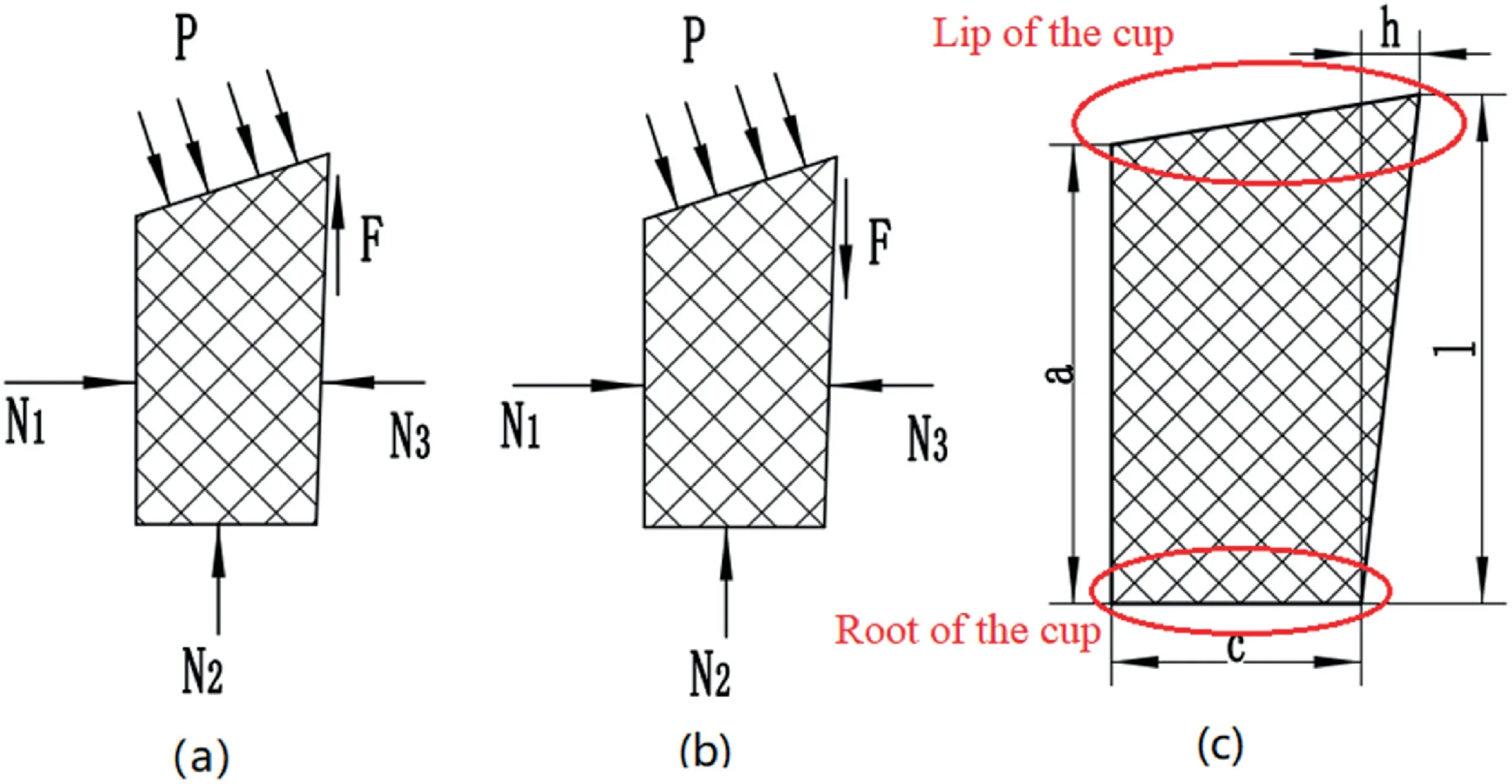
Fig.2.Force diagram of the rubber cup.
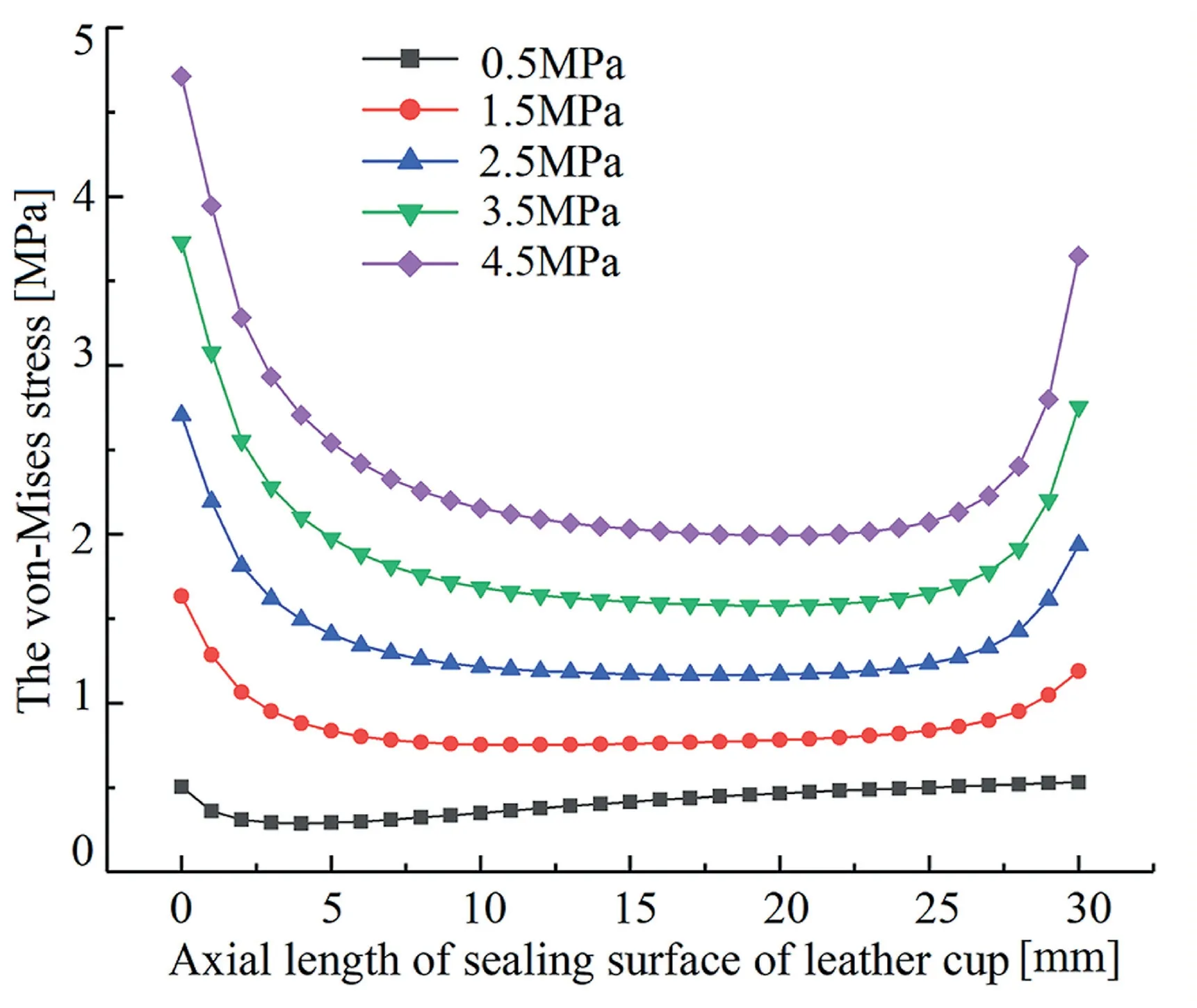
Fig.3.Stress curve of the cup under different loads.
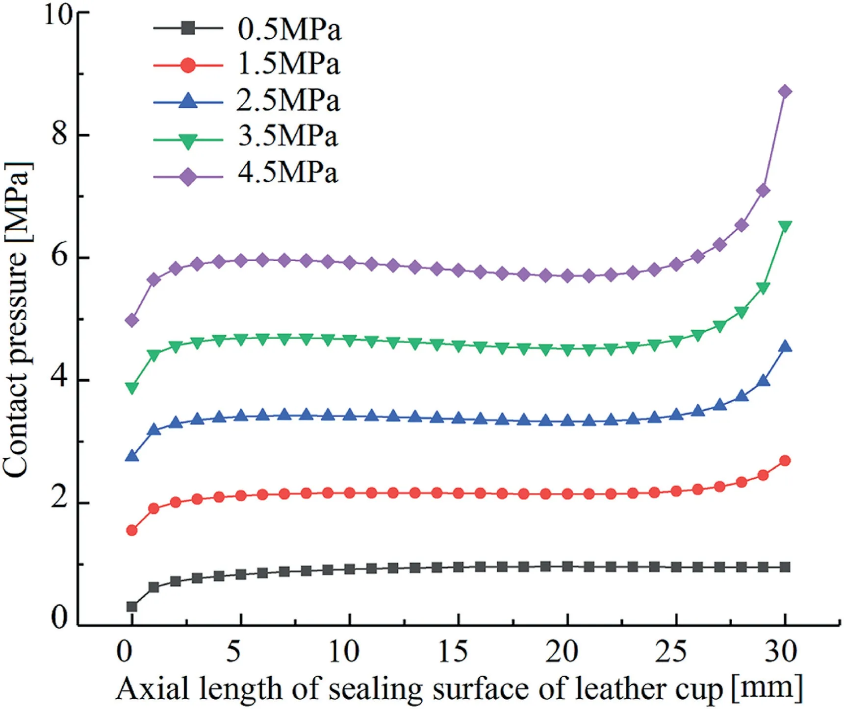
Fig.4.Contact pressure of the cup under different loads.
The larger equivalent stress of the rubber material will resulting in a decrease in the rubber material stiffness and cracks.Which can indirectly reflect the wear performance of the piston.The contact pressure of the piston cup reflects its sealing performance and directly affects the working efficiency of the mud pump.However,excessive contact pressure will accelerate the wear of the cup.The sealing performance of the cup is determined by the maximum contact pressure on the cup.However,the axis of the cup will always be eccentric with the cylinder liner in actual working conditions,which will cause the partial contact pressure of the cup to be too small,and leakage is prone to occur.At this time,the sealing performance of the cup is determined by the average contact pressure on the cup decided.
3.2.Working load
The working load squeeze the rubber cup and affect its contact mechanical properties.The axial component force causes the cup to be compressed axially,and the radial component force compresses the cup toward the cylinder liner.Figs.3 and 4 are the stress and contact pressure curves of the mud pump piston cup under different working loads.Except for the stress curve under the load 0.5 MPa,which is relatively flat.The change trends of other curves are all first decrease and then increase along the axial direction,stress concentration on the root and lips is becoming more and more obvious as with the working load increases.The contact pressure on the root of the cup is the smallest.Along the axial direction,the contact pressure gradually increases to a stable value,and it finally increases gradually at the lip of the cup,and the change rate increases with the load increases.Under different working loads,the average contact pressure of the cup increases linearly.
3.3.Friction coefficient
Friction is an important factor affecting the force of the rubber cup,and it has a certain restrictive effect on the rubber movement on the sealing surface of the cup.When the mud pump performs the mud discharge stroke,the surface tissue of the sealing surface of the cup tends to squeeze into the cavity formed by the steel core and the cylinder liner,and the tissue inside the cup tends to squeeze out of the cavity.Then,its deformation affecting the mechanical properties.Fig.5 shows the maximum stress and contact pressure of the rubber cup under different friction coefficients.As the friction coefficient increases,the maximum stress and contact pressure of the rubber cup gradually increase.The maximum stress of the cup with friction coefficient 0,0.05,0.10 and 0.15 appears on the inner lip of the cup.The maximum stress with friction coefficient 0.20,0.25 and 0.30 appears at the root of the sealing surface of the cups,and the extreme stress values changes significantly.
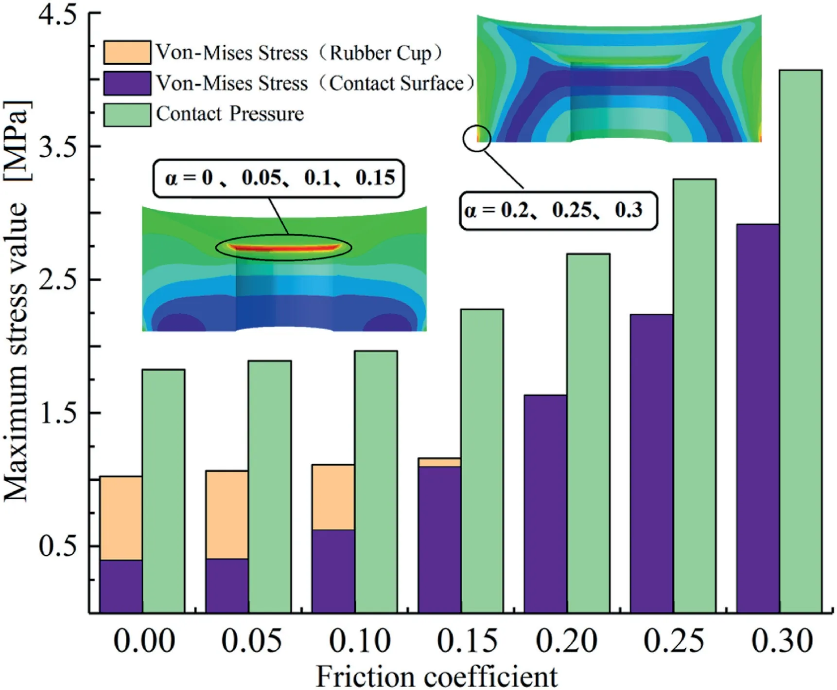
Fig.5.Stress and contact pressure of leather cup under different friction coefficients.
The greater the friction coefficient is,the greater the average contact pressure is,which can effectively prevent leakage.When the maximum stress on the contact surface of the leather bowl is too high,the sealing surface is easier slack,which accelerates the wear and cracks of the cup.In addition,an excessive friction coefficient will also accelerate the wear of the cup and the generation of heat.When the friction coefficient is small,the stress concentration on the inner wall lip of the rubber cup gradually becomes the main factor affecting the mechanical properties of the cup,during to the reduction of the stress.The average contact pressure of the leather cup is small,which often leads to leakage.Then,optimizing the size of the cup can increase the contact pressure of the sealing surface of the cup.
3.4.Cup size
3.4.1.Inner wall width
Fig.6 shows the stress distribution of the piston cup with different inner wall widths.The stress distribution in the middle of the sealing surface of the cup is relatively uniform,but stress concentration occurs at the root.Stress concentration is obvious at the root of the sealing surface when inner wall width of 10 mm,15 mm and 20 mm,while stress concentration appears at the root and lip of the sealing surface when inner wall widths are 25 mm and 30 mm.The stresses of the cup bottom under different inner wall width are not much different,the stress difference increases with the axial length of the cup sealing surface increases.The final stress difference reaches the maximum value at the lip of the cup.The stress of the cup lip with the inner wall width of 25 mm and 30 mm exceeds that of the cup root,but the stress of the cup lip with the inner wall width of 10 mm is not much different from that in the middle part.

Fig.6.Stress distribution of the cup with different inner wall widths.
Fig.7 shows the contact pressure distribution of the piston cup with different inner wall widths.With the increasing of the inner wall width,stress concentration appears on the lip of the cup gradually,and it becomes more and more obvious.The contact pressure distribution of the cup at the lips is roughly the same as the stress distribution.But the contact pressure at the root of the cup is smaller and changes little with the inner wall width increases,which is different from the stress concentration phenomenon at the cup root.The average contact pressure on the rubber cups changes small with different inner wall widths .
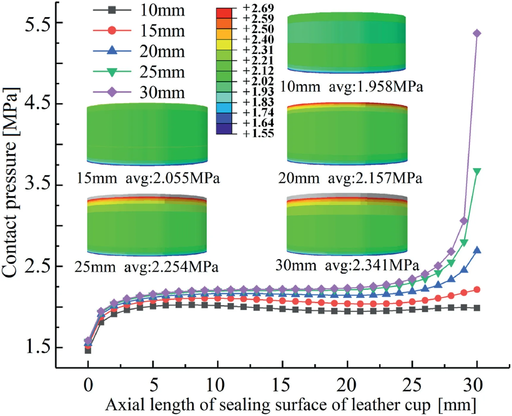
Fig.7.Contact pressure distribution of the cup with different inner wall widths.
Through the above analysis,the inner wall width has little effect on the distribution of the stress and contact pressure at the root of the cup and the middle section of the cup,but it has a greater effect on the stress and contact pressure of the lip.This is because the lip of the cup and the cylinder liner produce an “edge effect” during the mutual extrusion process,then the stress concentration phenomenon appears.As the inner wall width increases,the stiffness of the cup lip increases.The“edge effect”will be more obvious,and the cup is more prone to fatigue failure.
3.4.2.Interference
The interference determines the squeezing degree between the cup and the cylinder liner,which affects the contact pressure and the sealing performance of the piston.The greater the interference of the cup is,the greater the average contact pressure and the maximum contact pressure on the sealing surface of the cup are,and the smaller the probability of leakage is.However,when the interference is large to a certain level,the effect of the interference on the piston sealing performance will become smaller.And the friction force on the sealing surface of the cup will become larger,which will accelerate the cup wear.At the same time,a greater friction will generate more heat,accelerate the aging of the rubber and affect the life of the piston.
Fig.8 shows the stress distribution along the axial length of the sealing surface of the cup under different interferences.The stress curve shows a trend of first decreasing and then increasing.The stress near the root and the lip of the cup is larger and the absolute value of the stress gradient is larger.The stress in the middle part of the cup is smaller and the stress gradient increases with the interference increases.The maximum stress of the cup with 0.00 mm-0.75 mm is located at the root of the sealing surface of the cup,but the maximum stress of the cup is transferred to the inner lip when interference is 1.00 mm.Although the maximum stress on the sealing surface of the cup withh=1.00 mm is slightly smaller than that ofh=0.75 mm,but the maximum stress withh=1.00 mm on the entire cup is higher thanh=0.75 mm.The maximum stress of the cup withh=0 mm-0.75 mm has a small difference,and the maximum stress withh=1.00 mm-1.50 mm changes from 1.737 MPa to 3.274 MPa.
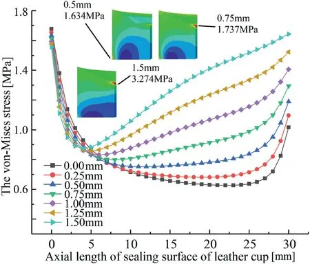
Fig.8.Stress distribution of the cup with different interferences.
Fig.9 shows the contact pressure distribution along the axial length of the cup sealing surface under different interferences.As the interference increases,the maximum contact pressure on the sealing surface of the cup gradually increase,and the contact pressure at the root of the cup gradually decreases.The contact pressure at the root of the cup is slightly higher than that of the middle part withh=0 mm,while the minimum contact pressure on the contact surface of the other cup appears at the root of the cup.The contact pressure in the middle of the cup with no interference is about 1.8 MPa,and the working pressure is 1.5 MPa.Leakage is very easy to occur if the piston is eccentric.
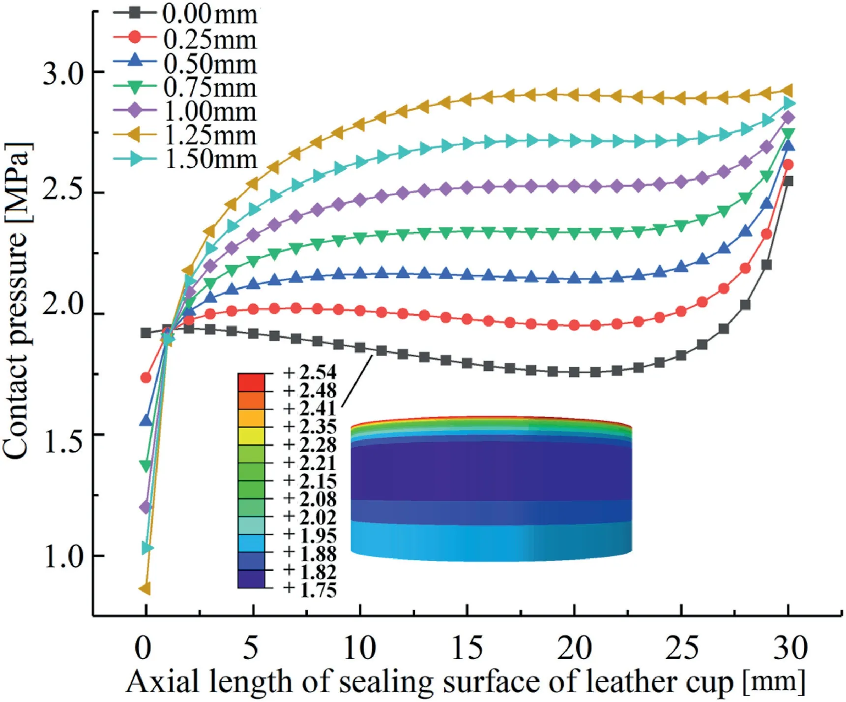
Fig.9.Contact pressure distribution of the cup under different interference.
3.4.3.Thickness
Fig.10 shows the stress distribution of the rubber cup on the sealing surface under different thicknesses.The stress distribution on the sealing surface of 18 mm,23 mm and 28 mm thick cups is basically same.The three curves show a trend of first decreasing and then increasing,and a longer stress gentle zone appears in the middle part.For the cup with thickness of 13 mm,a small bulge appears in the middle stress gentle area,and the lip stress concentration disappears.When the rubber cup thickness is 8 mm,the bulge degree in the middle curve of the rubber cup increases,the stress of the lip continue to decreases,and the stress concentration appears in the lip of the inner wall of the rubber cup,but the extreme stress is still at the root of the rubber cup.

Fig.10.Stress distribution of the cup with different thicknesses.
Fig.11 shows the contact pressure curve of the rubber cup on the sealing surface under different thicknesses.As the cup thickness decreases,the contact pressure near the cup root continue to increase,and the contact pressure near the lip of the sealing surface of the cup continues to decrease.The smaller the thickness of the cup is,the greater the average contact pressure is.
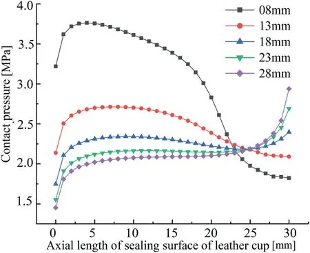
Fig.11.Contact pressure distribution of the cup with different thicknesses.
The results show that the stress of the cup with thickness 8 mm is too large,and the average contact pressure of the cup with thickness of 18mm,23 mm and 28 mm is small.Therefore,the sealing performance of the cup with thickness 13 mm is better under the load condition of 1.5 MPa.
4.Improvement of rubber cup
Contact pressure of the rubber cup sealing surface can be improved by optimizing the cup structure parameters for improving the sealing performance.But it has an upper limit on the optimization of the cup with smooth sealing surface.Three different rubber cup structures (semicircular,trapezoidal and triangular groove structures) and smooth rubber cups are compared in this section.The number of grooves on the three cups is 4,the groove width is 2 mm,and the distance between grooves is 3 mm.
Fig.12 shows the maximum contact pressure of four cups during the mud discharge process.The maximum contact pressure of the sealing surfaces of the four cups increases first and then stabilizes.The maximum contact pressure of the smooth cup is smaller than that of other three cups,the maximum contact pressure of the trapezoidal cup is the largest,and the difference between the triangular cup and the semicircular cup is small.When the displacement of the smooth cup is small(a small displacement after the mud pump changes from the mud suction stroke to the mud discharge stroke),the maximum contact pressure of the cup is small,which is only 1.6 MPa~1.8 MPa,while the working pressure is 1.5 MPa,and the piston movement speed is almost 0.At this time,the mud is easy to leak,and more sediment will enter into the sealing surface,which leads to premature wear failure of piston cup.
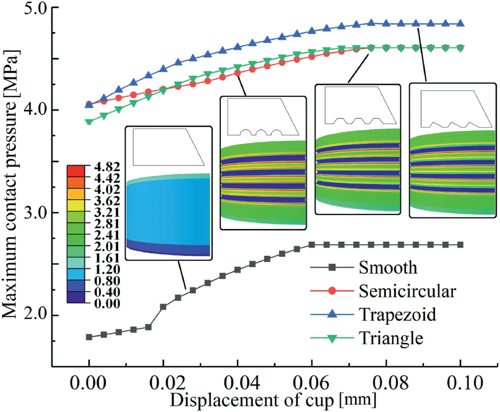
Fig.12.The maximum contact pressure distribution of the four cups.
Fig.13 shows the stress distribution on four cups.The high stress of the four cups are distributed near the sealing surface of the cups.By comparing the four cups,the overall stress of the semicircular groove and trapezoidal groove cups are the largest,followed by the triangular groove,and the smallest on the smooth cup.The stress extreme values of the semicircular groove and trapezoidal groove cups are concentrated in the groove,while the stress of the triangular groove is relatively uniform near the sealing surface,and there is no obvious stress concentration in the groove.
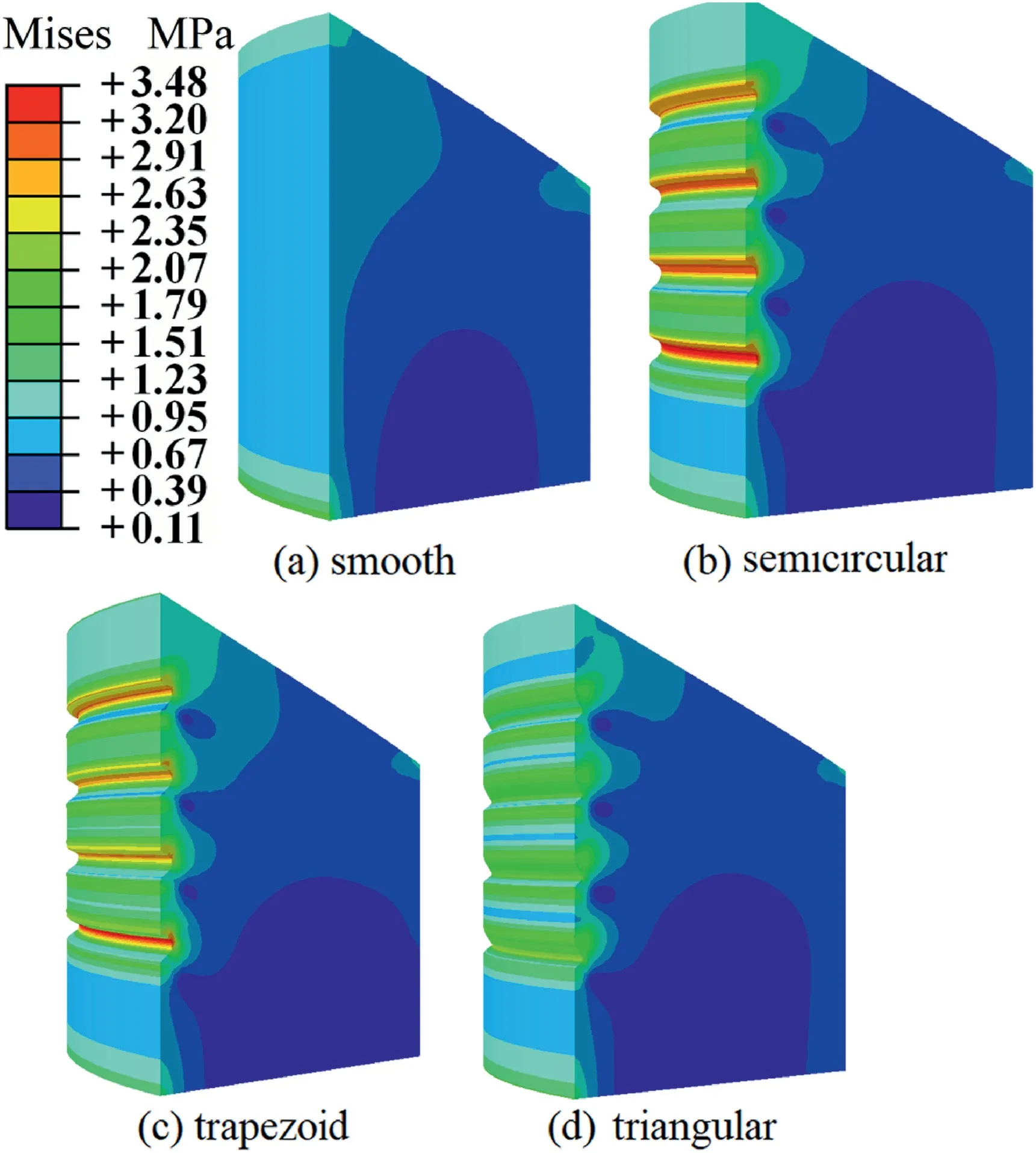
Fig.13.Stress distribution of the four cups.
Fig.14 shows the stress and contact pressure of four cups.The maximum stress and contact pressure of the smooth cup are the minimum value.Among the three kinds of grooved cups,the maximum stress difference between trapezoidal groove and semicircular groove is large,both of them are significantly higher than triangular groove.The maximum contact pressure difference among the three kinds of grooved cups is small,trapezoidal groove is slightly higher than the other two cups.
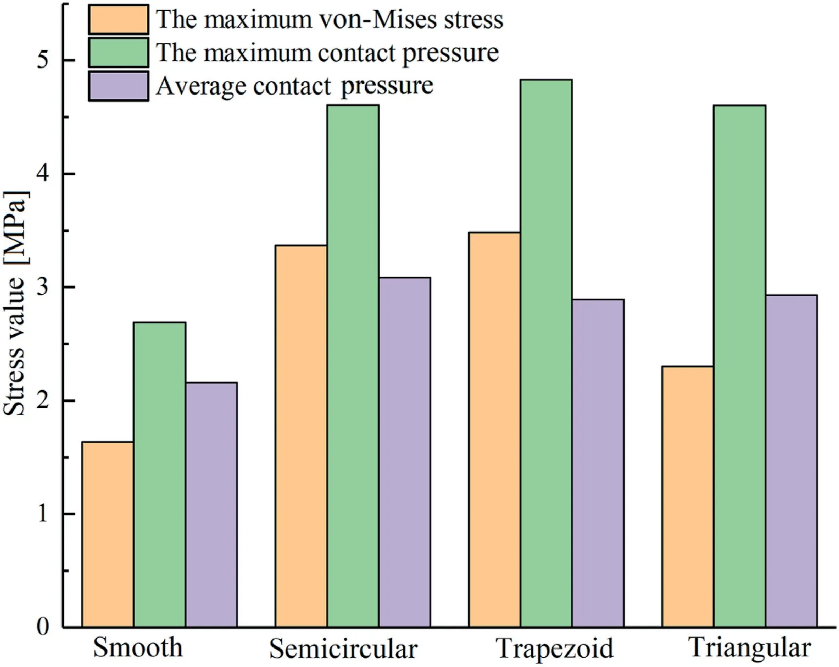
Fig.14.Stress of the four cups.
Through the above analysis,the groove structure can effectively improve the sealing performance.However,the groove structure destroys the original sealing surface of the rubber cup,which makes it easier for the lip structure of the rubber cup to compress to the cup root when discharging mud,which causing additional bending stress in the groove of the cup,then resulting in stress concentration at the cup root.The groove root is prone to failure due to fatigue,and cracks directly occur in serious cases.The addition of groove structure reduces the contact area between the sealing surface of the cup and the inner surface of the cylinder liner,thus increasing the contact pressure on the sealing surface of the cup.The contact pressure of all parts of the cup increases,which can prevent the leak.Especially,a circle of contact pressure intensive area is formed on the sealing surface between the two grooves,which enhances the adaptability of the cup to eccentric,vibration and other working conditions.Theoretically,the groove structure increases the contact pressure on the sealing surface of the cup,but a higher contact pressure may result in wear increase.The sealing surface of leather cup is very easy to be scratched by sediment under the harsh working environment of mud pump.The groove structure can store sediment mixed into the sealing surface and reduce the risk of scratching the cup.
5.Conclusions
(1) Working load has a great effect on the stress concentration at the lip and root of the cup.The friction coefficient has a great influence on the contact mechanical properties of the cup.The inner wall width of the cup has a little influence on the sealing performance,while the interference and the thickness of the cup have great influence on the sealing performance.
(2) The groove structure can improve the sealing performance of the cup,but it brings additional bending stress,resulting in stress concentration at the root of the groove.The triangular groove structure can better deal with the bending stress produced by the cup in the process of mud drainage,and the triangular groove structure has better mechanics than other groove structures.
Declaration of competing interest
The authors declared that they have no conflicts of interest to this work.
We declare that we do not have any commercial or associative interest that represents a conflict of interest in connection with the work submitted.
Acknowledgment
This research work was supported by Luzhou City Science and Technology Planning Project (2018-GYF-6),Chengdu International Cooperation Project (2019-GH02-00072-HZ) and Open Project of the Key Laboratory of the Ministry of Emergency Management of Fire Emergency Rescue Equipment (2019XFZB15).
杂志排行
Petroleum的其它文章
- Super gas wet and gas wet rock surface: State of the art evaluation through contact angle analysis
- Petroleum system analysis-conjoined 3D-static reservoir modeling in a 3-way and 4-way dip closure setting: Insights into petroleum geology of fluvio-marine deposits at BED-2 Field (Western Desert,Egypt)
- Development and performance evaluation of a high temperature resistant,internal rigid,and external flexible plugging agent for waterbased drilling fluids
- Anti-drilling ability of Ziliujing conglomerate formation in Western Sichuan Basin of China
- Production optimization under waterflooding with long short-term memory and metaheuristic algorithm
- Investigation of replacing tracer flooding analysis by capacitance resistance model to estimate interwell connectivity