Director distribution of nematic liquid crystals in a cylindrical cavity under electric field perpendicular to the cylindrical axis
2023-08-16SUNGuijiaoLIYanminZHANGYanjunZHANGHuiLIZhiguangZHENGGuiliZHUJiliang
SUN Gui-jiao, LI Yan-min, ZHANG Yan-jun, ZHANG Hui,LI Zhi-guang, ZHENG Gui-li, ZHU Ji-liang
(School of Science, Hebei University of Technology, Tianjin 300401, China)
Abstract: The curved liquid-crystal system has different characteristics from the planar liquid-crystal system.In this paper, the director of nematic liquid crystal in a cylindrical cavity is studied by applying a uniform electric field perpendicular to the axis of the cylinder under the strong axial anchoring boundary condition.Based on the elastic continuum theory of liquid crystal, the equilibrium equations and boundary conditions of the system are given. The analytical solution of the threshold electric field for the deformation of the director is obtained. It is found that different elastic constants will lead to the asymmetry of the change of the director on the cross section of the cylindrical cavity. It provides a more accurate theoretical analysis for the experimental research of photonic crystal fibers.
Key words: cylindrical cavity; electric threshold; nematic liquid crystal; director
1 Introduction
Nematic liquid crystals (NLCs) are anisotropic materials composed of rod-shaped molecules, and its optical anisotropy is determined by the orientation of rod-shaped liquid crystal (LC) molecules. It has been widely recognized that there are abundant physical phenomena in the finite and complex geometric structures.NLCs are often confined to some geometries, such as spherical droplets, capillary tubes and toroidal geometries[1-5]. The director of liquid crystals in a confined geometry is usually influenced by many factors, such as elastic anisotropy, surface anchoring, system size,external field effect,etc. Among the intricate geometries, the cylindrical cavity is considered to be the most intuitive geometry system[6]. A variety of alignment configurations of liquid crystals inside the cylindrical cavities are realized, which depends on different anchoring confidents and different elastic constants[7-11].
Liquid crystal is very sensitive to external field,which is used to control the orientation of liquid crystal molecules. The Fréedericskz transition in liquid crystals which is a second transition reflects a competition between elastic and electric or magnetic torques[12].The transition has been studied not only in planar liquid crystal systems, but also in liquid crystal cylindrical systems. Nematic liquid crystals in the concentrical cylindrical cells under magnetic fields have been studied and the Fréedericskz transition has been analyzed by applying a radial magnetic field[13]and a tangential magnetic field[14-15]. And the Fréedericskz transition in different initial states and anchoring conditions has been studied under electric fields in radial[16-19]and axial electric fields[19-20]. In addition, nematic liquid crystals in a cylindrical cavity under axial electric field have been theoretically analyzed and it was found that the director can form an axial transition from an escaped radial configuration when the electric value exceeds the critical value[21]and the flexoelectric effect affects the orientation of the director[22].
When the liquid crystal director changes, the optical[23-25]and electrical properties of the device will change, which provides a promising Whispering gallery modes (WGMs) tuning scheme for the study of liquid crystal filled cylindrical microcavity[26-27]. Yanget al. designed an electrically tunable microresonator based on a grapefruit microstructured optical fiber(MOF) infiltrated with NLCs[26]. In the crosssectional holes of the grapefruit MOF, the NLCs molecules turned out an escaped radial structure.When an electric field is applied in the direction perpendicular to the axis of the cylinder and with the enhancement of the applied electric field, the liquid crystal director gradually aligns along the direction of the electric field, and the WGMs resonance wavelength gradually shifts toward the shorter-wavelength region. Then Konget al. designed an electrically tunable microresonator based on the Kagomé photonic crystal fibers infiltrated with NLCs which the initial state of liquid crystal director is along the cylindrical axis[27]. After the electric field is applied perpendicular to the cylindrical axis, the director of the liquid crystal gradually aligns along the direction of the electric field with the increase of the applied electric field. And the WGMs resonance wavelength gradually shifts toward the longer wavelength region. In both literatures, the experimental thresholds electric field have been obtained through the images of the change of WGM resonant wavelength with the applied electric field. When the electric field direction is perpendicular to the axis of the cylindrical cavity, as in the above experimental model, there is still no theoretical study of liquid crystal transition. In order to better understand and apply the LC director deformation in cylindrical cavity under external field, we will do further theoretical research based on the liquid crystal elastic theory.
In this paper, the director distribution in nematic liquid crystals in cylindrical cavity under applied uniform electric field has been studied. Firstly, the geometric model of nematic liquid crystal in a cylindrical cavity under an electric field perpendicular to the cylindrical axis is described, and the equilibrium equation of the liquid crystal director is obtained by using the elastic theory. Then the expression of the threshold electric field under the one elastic constant approximation is derived by calculation. Finally, the director distribution of different liquid crystal materials in the cylindrical system is obtained by simulation.
2 Model and Methods
2.1 Establishment of theoretical model
The orientation distribution of nematic liquid crystals filled with a cylindrical cavity under uniform electric field effects has been discussed. We assume the cylindrical radius isaand the cylindrical length is infinite. As shown in Fig.1(a), the initial state of the liquid crystals is that the director is oriented along thez-axis (cylindrical axis) and a uniform electric field was applied in thex-axis direction.The liquid crystal molecules with the positive dielectric anisotropy (Δε>0) will turn to the direction of the electric field under the action of the electric field force. Therefore, it is reasonable to assume that the director changes in thex-zplane. As shown in Fig.1(b), the directorncan be defined as
Whereθis the angle between the director and thez-axis.
The electric field can be expressed as
2.2 Derivation of equilibrium equation
The equilibrium equation of nematic liquid crystal in cylindrical cavity according to the Frank theory was calculated[18]. The elastic free energy density is given by
The dielectric free energy caused by electric field is
The total free energy density of liquid crystals confined in the cylinder is
The total free energy per unitz-axis length is
whereDis a circular region, which is the section perpendicular to the axis of the cylinder.
For the convenience of studying the problem,the total free energy per unitz-axis length is transformed from rectangular coordinates into polar coordinates. There are some conversions, such asx=rcosφ,y=rsinφand dxdy=rdrdφ. The free energy per unitz-axis length is converted to
The equilibrium equation (8) can be obtained from the Euler-Lagrange equation.
The boundary conditions are
where,θmis the maximum amplitude ofθ(x).
According to the equilibrium equation and the boundary conditions, the director distribution of nematic liquid crystal in the system can be calculated.The solutions of the equilibrium equation satisfying the above boundary are different with different elastic constants.
3 Results and Discussion
3.1 One elastic constant approximation
In the following calculation, we solve the solution of the equation satisfying the boundary conditions in the one elastic constant approximation. The one elastic constant approximation satisfiesk11=k22=k33=k.
The equilibrium equation can be simplified to
The voltage threshold of director deformation can be calculated. At the threshold point, the angle is small,i.e.,θ≪1. The equation can be transformed into
The general solution of the above equation is solved by a method of separating variables. If we takeθ(r,φ)=R(r)Φ(φ) into Equation (12),we can obtain
The solution of Equation (13) isΦn(φ)=Ancosnφ+Bnsinnφ. According to the boundary conditions, we can obtain thatR(a)=0 andR(0) is a finite value. The solution of Equation (14) satisfying these boundary conditions is Bessel functionR(r)=Jn(λr)[28]. IfR(a)=0,is the zero of the Bessel functionJn(λr) andmrepresents the number of zeros.
Equation (15) gives the threshold value of director deformation in the one elastic constant, which has the same order of magnitude as the experimental results. The electric field response threshold of nematic liquid crystal in the cylindrical cavity under the electric field perpendicular to the axis of the cylindrical cavity is given for the first time. It also provides theoretical support for the electro-tunable micro-resonator.
Equations (8), (9) and (10) can also be solved by a finite-difference iterative method[8,29]. The liquid crystal parameters used to simulate the director distribution in the one elastic constant approximation are as follows:k11=k22=k33=k=5.85×10⁻¹²N,Δε=11.3 anda=0.5 μm. Fig. 2 shows the numerical results of the simulation. As shown in Fig.2(a),in the case of the one elastic constant approximation, the electric threshold is about 1.16 V/μm, which is completely consistent with the result obtained by Equation (15). Further, we simulated the change of the director angle with position on thex-yplane under another electric field of 1.4 V/μm exceeding the threshold, as shown in Fig.2(b). Different colors represent different angles. The angleθincreases gradually from the edge to the center of the cylinder, and the angle at the center is the largest. It can also be seen intuitively that the deflection of the angle under the electric field is symmetrical in thexandydirections. In thex-yplane, the line with the same director angle presents a symmetrical circular change. We also calculated the curves of the director angle withxwheny=0, and the curves of the director angle withywhenx=0 under different electric fields, as shown in Fig.2(c). The electric field values are 1.1 V/μm, 1.2 V/μm, 1.3 V/μm,and 1.4 V/μm. Under the same electric field, the curves inxdirection andydirection coincide. So the change of director inxdirection andydirection is symmetrical. The liquid crystal in the cylindrical cavity has splay deformation and twist deformation under the electric field. Under the one elastic constant approximation, the splay coefficient and the twist coefficient are equal. The free energy of splay deformation is the same as that of twist deformation, and then the director shows a circular symmetry orientation change.
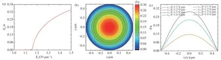
Fig.2 Effect of electric field on director distribution of liquid crystal in cylindrical system under one elastic constant approximation.( a) θm changed with the electric field;( b) θ changed with position in the x-y plane in the electric field of 1.4 V/μm;( c) Angle θ changed with the x-axis when y=0 and the angle θ changed with the y-axis when x=0 in the different electric fields;( c) Curves of x1 and y1 coincide, curves of x2 and y2 coincide, curves of x3 and y3 coincide, and curves of x4 and y4 coincide.
3.2 Anisotropic elastic constants
In order to better understand the change threshold and distribution of liquid crystal director, we further studied the director distribution of liquid crystal.The parameters of nematic liquid crystal 5CB (4-pentyl-4'-cyanobiphenyl) are as follows[30]:k11=5.85×10⁻¹²N,k22/k11=0.6,k33=7.8×10-12N, Δε=11.3 anda=0.5 μm. It is difficult to obtain an electric threshold expression. The numerical results are obtained by the finite-difference iterative method in Fig.3.Fig.3(a) shows the change of the maximum angle with the electric field. It can be seen that the electric threshold is about 1.04 V/μm.Fig.3(b) shows the change of the director angle with position in thex-yplane in the electric field of 1.3 V/μm. We can see that the angleθincreases gradually from the edge to the center of the cylinder,and the angleθis the largest at the center of the cylinder. The connecting line of the director angle of the cylindrical section is a slight non-circular asymmetric curve, which approximates a transverse ellipse. In order to further illustrate the symmetry of the change of director in thex-yplane, we calculate the curves of the director angle withxwheny=0 and the curves of the director angle withywhenx=0, in Fig.3(c). The values of electric field intensity are 1.0 V/μm, 1.1 V/μm, 1.2 V/μm and 1.3 V/μm. It can be seen that the curves ofx1andy1,x2andy2,x3andy3,andx4andy4do not coincide perfectly. But the deviation between the two curves is very small. At the same distance from the center of the circle, the angle in thex-axis direction is greater than that in they-axis direction. Therefore,it is known that the director has small asymmetry in thexdirection andydirection. The splay coefficient of liquid crystal is greater than the twist coefficient, and then the free energy of the splay deformation of liquid crystal is greater than the free energy of the twist deformation. The difference between the coefficients of splay deformation and twist deformation leads to the asymmetric change.
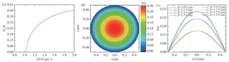
Fig.3 Effect of electric field on director distribution of liquid crystal 5CB in cylindrical system. (a) θm changed with the electric field; (b) θ changed with position in the x-y plane in the electric field of 1.3 V/μm; (c) Angle θ changed with the x-axis when y=0 and the angle θ changed with the y-axis when x=0 in the different electric fields.
The elastic constants of some lyotropic liquid crystals are quite different from those of thermotropic liquid crystals, even one order of magnitude.For example, nematic lyotropic chromonic liquid crystal disodium cromoglycate (DSCG) has a relatively smallk22, which is one order of magnitude smaller thank11. We takek11=5.85×10⁻¹²N,k22/k11=0.05 for calculation. In order to compare the effect of elastic anisotropy, the above dielectric anisotropy parameter and cavity radius are still adopted.It can be seen from Fig.4(a) that the threshold voltage is about 0.80 V/μm. The liquid crystal elastic constantK22is much smaller thanK11, which is quite different from the above two cases. In Fig.4(b),the change of the angle with position in thex-yplane in another electric field of 1.1 V/μm exceeding the threshold was simulated. The angleθincreases gradually from the edge to the center of the cylinder, and the largest angle is at the center of the cylinder. There is an obvious non-circular asymmetric change in the connecting line of the director angle of the cylindrical section. It can be seen intuitively that the change ofangleθwith position is asymmetric. We also calculate the curves of the director angle withxwheny=0 and the curves of the director angle withywhenx=0 in four different electric fields of 0.6 V/μm, 0.9 V/μm, 1.0 V/μm and 1.1 V/μm, as shown in Fig.4 (c). According to Fig. 4(c), there is obvious asymmetry alongxaxis andy-axis under a same electric field. At the same distance from the center of the circle, the angle in thex-axis direction is greater than that in they-axis direction, which is more obvious than 5CB liquid crystal. The splay elastic constant is one order of magnitude larger than the twist elastic constant, resulting in obvious asymmetric change of the director.
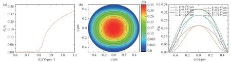
Fig.4 Effect of electric field on director distribution of liquid crystal with k22/k11=0.05 in cylindrical system. (a) θm changed with the electric field; (b) θ changed with position in the x-y plane in the electric field of 1.1 V/μm; (c) Angle θ changed with the xaxis when y=0 and the angle θ changed with the y-axis when x=0 in the different electric fields.
Further, we takek11=5.85×10⁻¹²N,k22/k11=2 for simulation calculation. The dielectric anisotropy parameters and cavity radius are the same as above. It can be seen from Fig. 5(a) that the threshold voltage is about 1.40 V/μm. In Fig.5(b), the change of the angle with position in thex-yplane in another electric field of 1.8 V/μm exceeding the threshold was simulated. The largest angle is at the center of the cylinder and the angleθincreases gradually from the edge to the center of the cylinder. The change ofθwith position inx-yplane is still asymmetric, but different from the previous case ofk22<k11, the line with the same angle is similar to a vertical ellipse. We also calculate the curves of the director angle withxwheny=0 and the curves of the director angle withywhenx=0 in four different electric fields of 1.2 V/μm, 1.6 V/μm,1.7 V/μm and 1.8 V/μm, as shown in Fig.5 (c).It is still asymmetric alongx-axis andy-axis under a same electric field. However, unlike the previous one, the angle in they-axis direction is larger than that in thex-axis direction at the same distance from the center of the circle. The twist elastic constant is larger than the splay elastic constant resulting in the asymmetric change of the director.
In our model, the director has only splay and twist deformation under thex-axis electric field. We assume thatkin Equation (15) can be replaced by(k11+k22)/2 and the threshold formula can be
The change of the electric threshold withk22/k11by Equation (16) is given, as shown in the black curve in Fig.6. The thresholds calculated by numerical simulation are also shown in Fig.6, which are represented by red dots. The ratios of the twist elastic constant and the splay elastic constant arek22/k11=1,k22/k11=0.6,k22/k11=0.05 andk22/k11=2, respectively. The threshold results are almost consistent. We also calculated the relationship between the threshold and the value of the bend elastic constantk33, and found that the threshold is independent of the elastic constantk33. The above results prove the reliability of our hypothetical equation.
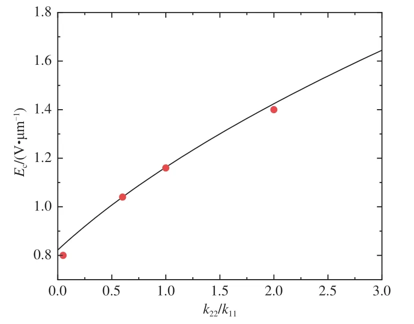
Fig.6 Threshold electric field changed with k22/k11 fields
4 Conclusions
In this work, we adopted the cylindrical cavity filled with nemaic liquid crystals to investigate the effect of external electric field on the distribution of liquid crystal director. When the electric field exceeds the electric field threshold and increases gradually, the liquid crystal director gradually turns towards the electric field. In the one elastic constant approximation, the threshold electric field expression has been obtained. The director changes symmetrically under the approximation of one constant.And the threshold electric field in the anisotropic elastic constants is approximately equal to the result of substitutingk=(k11+k22)/2 into the above expression. It is found that the difference between the twist elastic constantk22and the splay elastic constantk11leads to the asymmetry of the variation of the director on the cross section of the cylindrical cavity. Our research has important guiding significance for studying on the orientation properties of the liquid crystals in the cylindrical cavity under the electric field and the design of the liquid crystal devices in the cylindrical cavity.