Electronics system for the cosmic X‑ray polarization detector
2023-07-11HuiWangDongWangRanChenYanWeiKuiHongBangLiuZongWangFanHuanBoFengJinLiJunLiuQianLiuShiChenYuanKangYangZhuoZhouZiLiLiShiQiangZhouNiFang
Hui Wang ·Dong Wang ·Ran Chen ·Yan‑Wei Kui ·Hong‑Bang Liu ·Zong‑Wang Fan ·Huan‑Bo Feng ·Jin Li ·Jun Liu ·Qian Liu ·Shi Chen ·Yuan‑Kang Yang ·Zhuo Zhou ·Zi‑Li Li ·Shi‑Qiang Zhou ·Ni Fang
Abstract This study presents an electronics system for cosmic X-ray polarization detection (CXPD).The CXPD was designed as a high-sensitivity soft X-ray polarimeter with a measurement energy range of 2–10 keV carried by a CubeSat.A stable and functionally complete electronics system under power and space constraints is a key challenge.The complete CXPD electronics system (CXPDES) comprises hardware and firmware.CXPDES adopts a three-layer electronic board structure based on functionality and available space.Two gas pixel detectors (GPDs) were placed on the top layer board, and CXPDES provided the GPDs with voltages up to − 4000 V.Each GPD signal was digitized, compressed, encoded, and stored before being transmitted to the ground.The CXPDES provided stable and high-speed communication based on a scheme that separated command and data transmission, and it supports the CXPDES in-orbit upgrade.In addition, environmental monitors, silicon photomultiplier (SiPM) triggers, power management, GPDs configuration, and mode switches were included in the overall operating logic of the CXPDES.The results obtained by testing the CXPDES showed that it satisfied all the requirements of CXPD.The CXPDES provides design experience and technological readiness for future large-area X-ray polarimetry missions.
Keywords X-ray polarimeter ·Electronics ·CubeSat ·Gas pixel detector ·FPGA
1 Introduction
X-ray polarimetry is a powerful tool for studying astrophysics and helps understand the physical processes of X-ray sources in the universe [1, 2].Early soft X-ray polarimetry was primarily based on Bragg crystal polarimeters [3, 4].An efficient photoelectric effect-based X-ray polarization measurement method which uses a gas pixel detector (GPD) to measure X-ray polarization by measuring the photoelectron tracks produced by the interaction of X-ray photons with gas molecules [5], was proposed in 2001 [6].The GPD exhibits excellent potential for high-sensitivity X-ray polarimetry.X-rays from high-energy astrophysical objects are significantly obstructed by the Earth’s atmosphere and therefore must be detected by satellites in space.GPD-based X-ray polarimetry has been continuously developed in recent years, and several detection missions are in a launched or ground-ready state [7–9].
The cosmic X-ray polarization detector (CXPD) is a highsensitivity soft X-ray polarimeter with a measurement energy range of 2–10 keV.The CubeSat with the CXPD payload is scheduled to be launched in the first quarter of 2023.CubeSats are tiny satellites with a cube-shaped structure that are lightweight, small, and inexpensive [10].Owing to technological development, CubeSats have become an effective platform for astronomical experiments [11].The CXPD has two GPDs,each consisting mainly of a gas microchannel plate (GMCP)and a Topmetal-II−sensor.The GMCP functions similarly to a thick-gas electron multiplier (THGEM) as an electronmultiplying device.Electrons undergo avalanche multiplication via THGEM to produce sufficiently distinct tracks.The THGEM possesses the advantages of robustness, large gain,low cost, and ease of manufacturing [12, 13].Topmetal-II−is a low-noise, high-precision, radiation-resistant pixel array sensor with an effective detection area of 6 mm × 6 mm and a 72 × 72 pixel array.At room temperature in ambient air, the equivalent noise charge of Topmetal-II−is only 13.9 e- [14,15].The modulation factor derived from the tracks of 100%polarized 4.5 keV is 28.6% ±1.0% at 53.3% signal efficiency,with a residual modulation of 2.1% ±0.7% at 60.4% signal efficiency for unpolarized 5.9 keV X-rays when Topmetal-II−was applied in soft X-ray polarimetry [16].The Topmetal-II−analog signal was read using the rolling shutter method controlled by an external clock.Increasing the external clock frequency improves the energy and position resolution of the detector but results in higher power consumption and larger data.Satellite payloads have stringent power consumption,data transmission and volume requirements [17, 18].
The CXPD not only serves as a stand-alone detector for X-ray polarization measurement but is also an important reference for future large-area X-ray polarimeters.The main challenges of the CXPDES include high-speed detector readout,complete on-satellite operational logic, and highly integrated hardware in a limited space.Simultaneously, the presence of numerous high-energy particles in space can induce a singleevent effect and cause state changes or even destruction of electronic devices and integrated circuits [19].Satellite electronics have extremely high-reliability requirements.Thus,system stability and security protection mechanisms must be considered in both the hardware and firmware.This study presents a specific electronic system for CXPD which can independently perform detector control and monitoring, highspeed data processing, multiple-device control, and in-orbit upgrades.A detailed electronic implementation is presented in Sect.2, and the corresponding firmware is discussed in Sect.3.Data processing and compression schemes are analyzed in Sect.4.The results of ground tests are presented in Sect.5.
2 Electronics implementation
2.1 Structure
The CXPD electronics were designed on the basis of 1U,which is a standard unit (a cube of volume 10 cm × 10 cm ×10 cm and weight approximately 1 kg).For detection tasks,the electronics system was divided into three printable circuit boards (PCBs), depending on the main function.In the horizontal direction, the CXPDES consisted of three boards with dimensions of 94 mm × 94 mm.In the vertical direction, the board spacing was 10 mm, and the thickness of each board was 2 mm.The total height of the CXPDES, including the device height, was 44 mm.The front-end electronics(FEE) board primarily consisted of GPDs, silicon photomultiplier (SiPM) trigger circuits, and GPD data readout circuits.The back-end electronics (BEE) board comprised the main controller, power regulator, data and firmware memory, communication interface and devices, and an external clock.The high-voltage (HV) board comprised a GMCP lower-surface feedback circuit, dividing circuits, HV chip,HV configuration, and HV monitoring.Interboard communication and power supply were via a field-programmable gate array (FPGA) mezzanine card (FMC).The CXPDES had only one external interface, which was sufficient for power supply, data transmission, command transmission,and in-orbit upgrades.Figure 1 shows the overall schematic of the CXPDES, and we will describe the detailed design in subsections.
2.2 FEE
The GPD must be placed on top of the CXPDES for soft X-ray polarization measurements.On the FEE board, two circular pin arrays with a diameter of 36 mm and a hole of 0.8 mm were used to connect to the GPDs.Twenty of the array pins were control pins for Topmetal-II−, and four pins were control pins for the GPD environmental monitoring sensors.A photograph of the Topmetal-II−sensor bonded to a ceramic pedestal and a schematic of the sensor architecture are shown in Fig.2.The Topmetal-II−output signal is a single-ended analog signal, whereas the input of the highspeed analog-to-digital converter (ADC) [> 10 million samples per second (MSPS)] is usually a differential signal.The original single-ended signal was converted to a differential signal by a fully differential amplifier with an amplification factor of 1, digitized by a 40 MSPS, 12-bit parallel ADC,and finally transmitted to the BEE board via the FMC.Figure 3a shows the functional block diagram of the FEE board.To achieve optimal reliability, the data acquisition process was divided into two independent circuits for acquiring data from the two GPDs.The external SiPM signal was processed by a charge-sensitive preamplifier, CR-RC shaper, and comparator before digitization and transmitted to the BEE board via the FMC [20].Both Topmetal-II−and the comparators required configuration signals with settable voltage values and two independent multi-channel digital/analog converters(DACs) to provide the required configuration signals.The chips may suffer from single-particle effects because of the large number of energetic particles in space.The core design concept of the FEE board was to ensure that a single detector could independently perform X-ray polarization measurements.The two detectors did not affect each other, thereby minimizing system risk.
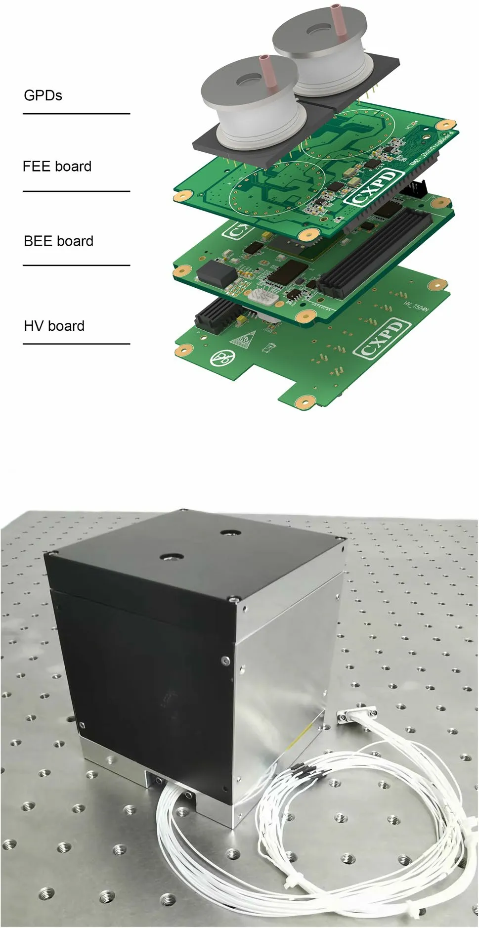
Fig.1 (Color online) Two GPDs are placed symmetrically on the FEE board with a center line, and the surrounding positioning holes are used to fix the electronics board to the payload shell
2.3 BEE
Figure 3b shows the functional block diagram of the BEE board.The multiple high-speed devices and in-orbit algorithms in CXPDES require powerful computing capabilities in the main controller.A Xilinx Kintex-7 family of FPGAs was used.The FPGA has higher speed and more powerful computing power than a general-purpose processor, which has obvious advantages in high-speed digital circuit design and multichannel signal handling [21].The FPGA was configured with a 1 GB flash device.Multiple files were stored in the flash memory to enable correct system booting in case of raw file damage.The backup configuration file was booted in the address order to reduce the system boot risk in the case of an incorrect FPGA configuration file.In the special environment of satellite electronics, external memory allows the electronic system to support in-orbit upgrades to adjust the firmware during satellite operation.The BEE board was connected to the satellite platform using a 15-pin custom functional aerospace-specific connector, and the main functional pins are listed in Table 1.
The CXPDES used 5 V and 12 V power supplies as the main power supply and solely for HV devices, respectively.A power supply module converted the 5 V power supply to generate 1.0, 1.2, 2.5, 3.3, 4.8 and − 5 V for different devices.The detector data reached data rates of 32 Mbps or higher for uncompressed or extreme event rates.The data rate was proportional to the scanning frequency of Topmetal-II−, which was related to the detector performance;therefore, fast Ethernet was used for data transfer to match the data transmission requirements at a 2 MHz Topmetal-II−scanning frequency.The satellite platform transmitted commands to the BEE board via a controller area network(CAN) bus, which was a standard bus for local area networks widely used in control systems and had advantages in terms of security, reliability, and low power consumption [22, 23].Functions such as startup detection, device management,switch-on/off configuration, and data transmission control were executed via the CAN bus.The details are introduced in Sect.3.CXPDES and satellites do not transmit data in real time, and the data are stored in non-volatile memory.The detector generated 28.8 GB of uncompressed data per hour with data write and read speeds of 64 Mbps.Support for the embedded multimedia card (eMMC) 5.0 protocol of 64 GB nand flash memory was used to store data.
2.4 HV
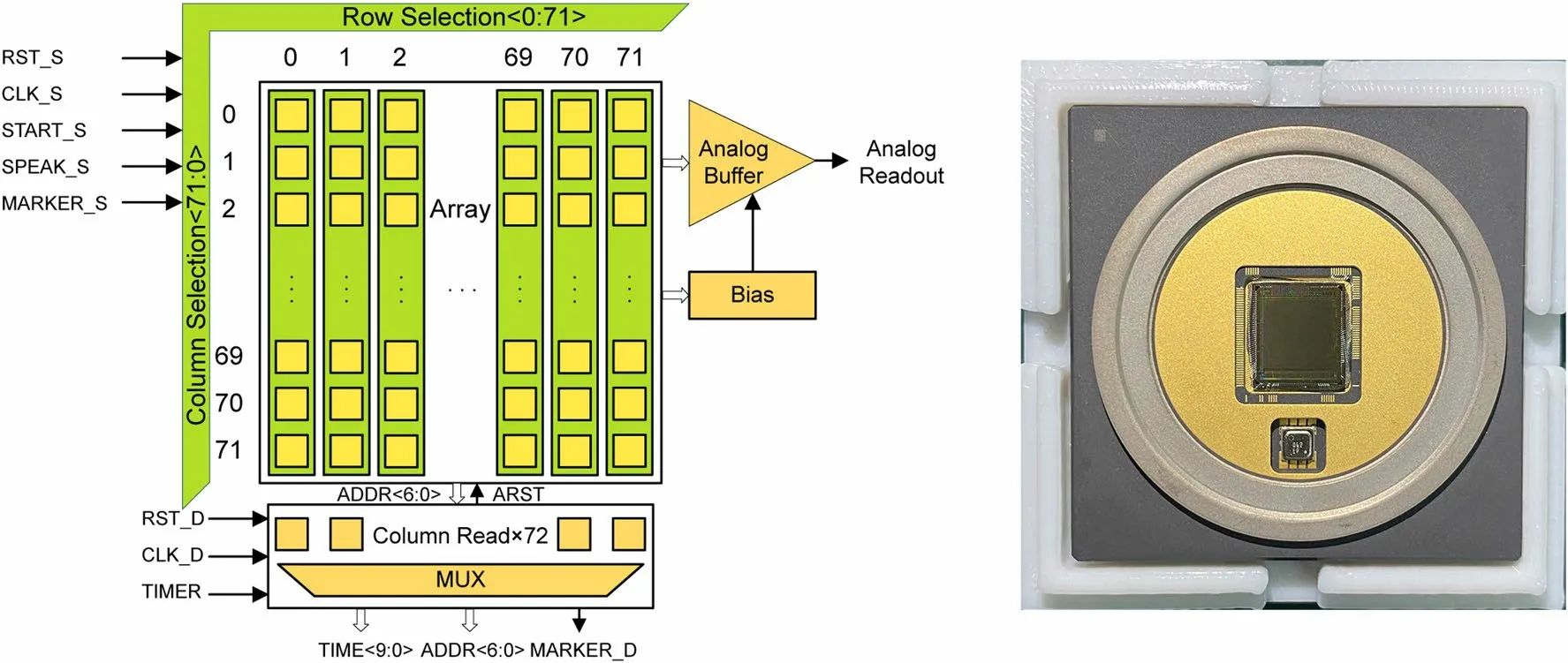
Fig.2 (Color online) Schematic of the sensor architecture (left) and photograph of a ceramic base.The Topmetal-II− sensor is placed in the center of the base, and a temperature and gas pressure sensor is positioned below it

Fig.3 (Color online) Functional block diagram of CXPDES
The HV chip used in the CXPDES was 16 mm high and was placed on the bottom layer of the HV board.Figure 3c shows the functional block diagram of the bottom board,and the HV board is dedicated to place HV devices.The core device on the HV board was the A7504N, which generates a maximum negative high voltage of −4 kV at 100vA.The output route was kept away from the metal to avoid a high-voltage discharge when the solder mask layer breaks down, as shown in Fig.4.The A7504N set the output voltage and current via the voltage and current setting pins and provided the actual output voltage and current via the feedback pins.The high-voltage output was divided by a dividing circuit to obtain the voltage required for the GPDs.The high-voltage flexible wire passed through the non-metalized holes of the FEE and BEE boards to output a high voltage to the GPD.This avoided the influence of high voltages on other devices.In our experiments,we found that the GMCP lower surface generated a pulse signal at the moment of photon arrival which could be used as a GPD trigger signal after the comparator and to improve the energy resolution by measuring the amplitude of this signal.In addition, to ensure independence, the bottom board had two separate GMCP lower-surface circuits corresponding to the two GPDs, and both GMCP lowersurface circuits had comparators and ADCs.

Table 1 CXPDES external interface

Fig.4 (Color online) The high-voltage discharge area is located in the center red box (top).The discharge phenomenon disappears when the high-voltage chip and high-voltage output are located on the bottom and top layer of the PCB, respectively (bottom)
3 Operation logic
3.1 Flight firmware
A top-down approach was used for the firmware to consider the scalability of the development.The block diagram of the architecture is shown in Fig.5.The clock module was configured with all clocks.Four different clocks were used in the firmware, and the system, Ethernet, GPD sampling, and Topmetal-II−clocks were 200,125, 40 and 2 MHz, respectively.Ethernet used UDP protocol with a transmission rate of 100 Mbps to communicate with the satellite computer.The UDP message consisted of a 36 bytes header and a 1024 bytes data segment, and the message format was defined by the satellite platform.The CAN module supported the CAN2.0B protocol with a communication baud rate of 500 kbps and a sampling rate generally set at the maximum baud rate tolerance, which was typically 75%.There was contention on the bus, and the host computer needed to enable hardware retransmission to communicate with the OBC using 29-bit CAN ID extension frames.The commanddecoding module parsed the remote control data from the CAN and controlled different modules to work according to the command content.Data storage was divided into four steps.First, the erosion module removed scatter noise from the sampled GPD data.Second, the denoised GPD data were zero-compressed using the compression module.Third, the trigger module determined whether to store the data according to the compressed data.Finally, the data were stored in the eMMC by the storage module.After receiving the command, the upload module uploaded data to the satellite platform and configured the next storage address.The upload module supported data retransmission and specified data reading.
The typical polarization measurement workflow is as follows.
Power on: The satellite computer supplies power to the payload according to the preset plan.The CXPDES completes the initialization within 50 μ s after powering on and receives the control command from the satellite platform after the initialization is completed.The control command contains the relevant settings for the detection mission (such as detector settings and high-voltage settings).Finally, CXPDES starts the detection mission after receiving the detector start command.
During the detection process, the Topmetal-II−output data are quantized, eroded, compressed, triggered, and stored in the eMMC in real time.The GMCP lower-surface signal, SiPM trigger data, Coordinated Universal Time(UTC), system operation status, and monitoring data are stored in an eMMC with different headers.The management module inside the CXPDES performs real-time adjustments based on the system operation status.
Shutdown: Before shutdown, the satellite platform sends a shutdown command to the payload.The payload stores the address of untransmitted data, which is read at the next power on initialization.The new GPD data continue to be stored after the address, and this design can complete lossless storage and data transmission between multiple detection missions.The CXPDES sends a power-off command to the satellite platform after the voltage drop in the highvoltage circuit is completed and the CXPDES stops working.

Fig.5 Block diagram of the firmware.The payload on-board computer board (POBC) sends commands to the command decode module, which mainly controls the operation of CXPDES
3.2 Command and control
Commands and data transmission is done between the satellite computer and CXPDES.There are 17 commands in the CXPDES, each of which contains three types of information: frame type, command number, and command parameters.Each command was 8 bytes long.The functions of the simplified commands are shown in Table 2.A variety of monitoring data were packaged and sent to the satellite computer via the CAN bus at a frequency of 1 Hz in the test mode.The monitoring data included the GPD internal temperature and pressure, HV module output voltage and current, and CXPDES operating status.Commands 02–04 configured the high-voltage output voltage, current and enable.Commands 05 to 11 were used to set the pixel chip reference voltage, analog data output bias voltage, SiPM threshold voltage, and GPD operating mode.Changing the pixel chip reference voltage changed the decay time and particle sensitivity of the GPD.The analog data output bias voltage maintained the output of the GPD within the valid input range of the ADC, while the SiPM threshold voltage was used to calibrate the SiPM detection validity.The CXPDES received 12 commands to transmit the stored data to the satellite computer, and 13 commands were used to control the compression effi-ciency.Commands 14 and 15 adjusted the trigger effi-ciency of the two GMCP lower-surface circuits.Commands 16–18 are listed in Table 2.
4 Data processing
The analog output of the GPD was quantized by the 12-bit ADC and transmitted via Ethernet.The GPD single-pixel output was 2 bytes after the complementary bit because the smallest unit of Ethernet data transmission was a byte.Large amounts of data complicate offline analysis, and the CubeSat in this detection mission cannot downlink up to hundreds of gigabytes of data to the ground.Real-time data compression was used to solve this problem.
There are two methods of data compression.The first method, the pedestal compression method (PCM), periodically selects 27 frames of data after the detector is turned on to calculate the pedestal value.Each pixel has a pedestal value that was stored as a threshold value.For a better application to hardware calculations, the modified expression is as follows:
A schematic of the PCM architecture is presented in Fig.6.During the detection, a pixel with an ADC value greater than the threshold value was identified as the signal pixel.When the number of signal pixels was greater than the threshold number, it was determined that a particle hit the GPD at that moment and the frame data were transmitted to the erosion module.The second method is the difference compression method (DCM), in which the ADC value of the previous frame for each pixel is stored in a separate register.The ADC of the current frame for the same pixel was compared with the ADC value of the previous frame.If the ADC value difference was greater than the preset value, the pixel was identified as a signal pixel.When the signal pixels were greater than the preset number, the current frame was transmitted to the erosion module as a valid frame.A schematic of the DCM architecture is presented in Fig.7.Both PCM and DCM accomplish data compression by discarding nosignal data frames and retaining only track data frames.The advantages of PCM are its simple logic and low-resource consumption; however, the space environment is complex,and the acquisition of pedestal values is not in real time,which easily leads to inaccurate data after compression.The long decay time for some pixels leads to data sizes that are larger than ideal.The advantage of DCM is that the compression effect is unaffected by pedestal noise, strong antiinterference capability, and high event integrity; however,the pixel difference threshold and number of signal pixel thresholds must be manually assigned.We chose the DCM,and the thresholds were configured via the bus.
There are two methods of data storage: storing the entire data frame and storing only the signal pixels.To estimate the data size in these two ways, we assumed a single GPD event rate of 0.8 count/s, double the redundancy design and 24-h power on.The differences between storing the entire frame and the signal pixels are listed in Table 3.Single-event storage of three frames (previous, current and following) for both the methods is included.
Finally, we chose to store only the signal pixels.This method minimized the stress of data transmission, and the entire frame was reconstructed via data processing during offline analysis.The format of all the data is shown in Fig.8.The ground decoded the data according to the data header,read in four bytes, and the 8 bytes data were decoded by merging two 4 bytes data.
5 Tests and measurements
5.1 Power on test
Voltage variations owing to the satellite power supply affect the GPD performance.The DC–DC module of the CXPDES provided a stable power supply for the GPDs.However, itgenerates an input inrush current when the CXPDES is powered on.An excessive input inrush current can affect other devices and loads that use the same input power supply.We first provided a 5 V power supply and then a 12 V power supply according to the CXPDES startup sequence.The inrush currents corresponding to the 5 V and 12 V power supplies are 1.04 A/20 ms and 240 mA/8.2vS, respectively(Fig.9).The input inrush currents of both power supplies were within the normal range.When the CXPDES was in the detection state, the stable working current of the 5 V power supply and the power consumption were 0.83 A and 4.15 W, respectively; the stable working current and power consumption of the 12 V power supply were 0.03 A and 0.36 W, respectively.The total power consumption of the CXPD was 4.51 W, which was sufficient to meet the Cube-Sat’s requirement of power consumption within 10 W for a single payload.
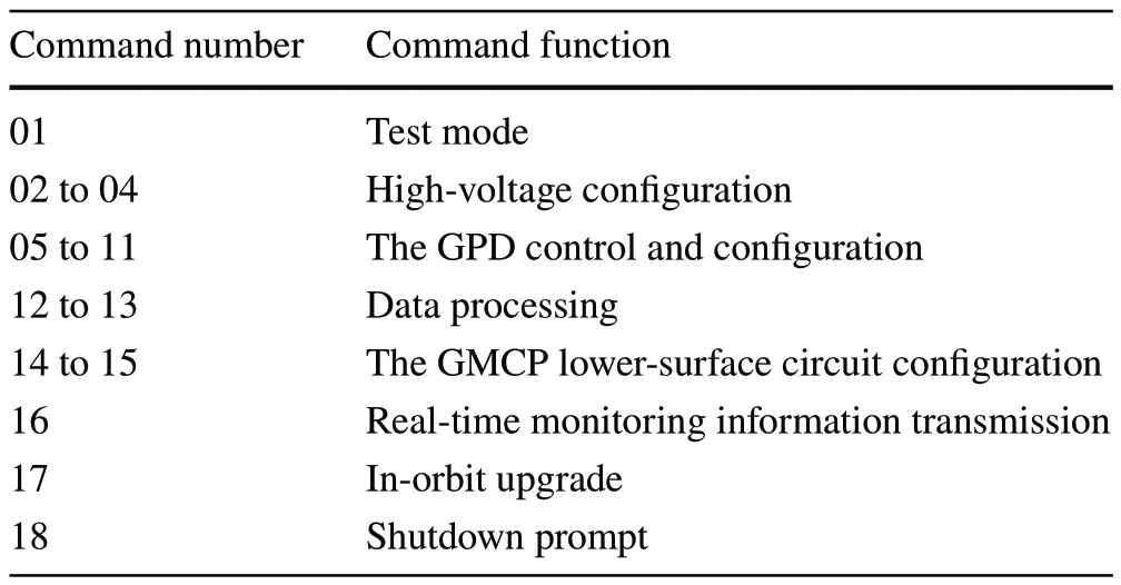
Table 2 Command function

Fig.6 (Color online) The 16-bit fixed-point integer pixel data are converted to 32-bit single-precision floating-point pixel data for calculation
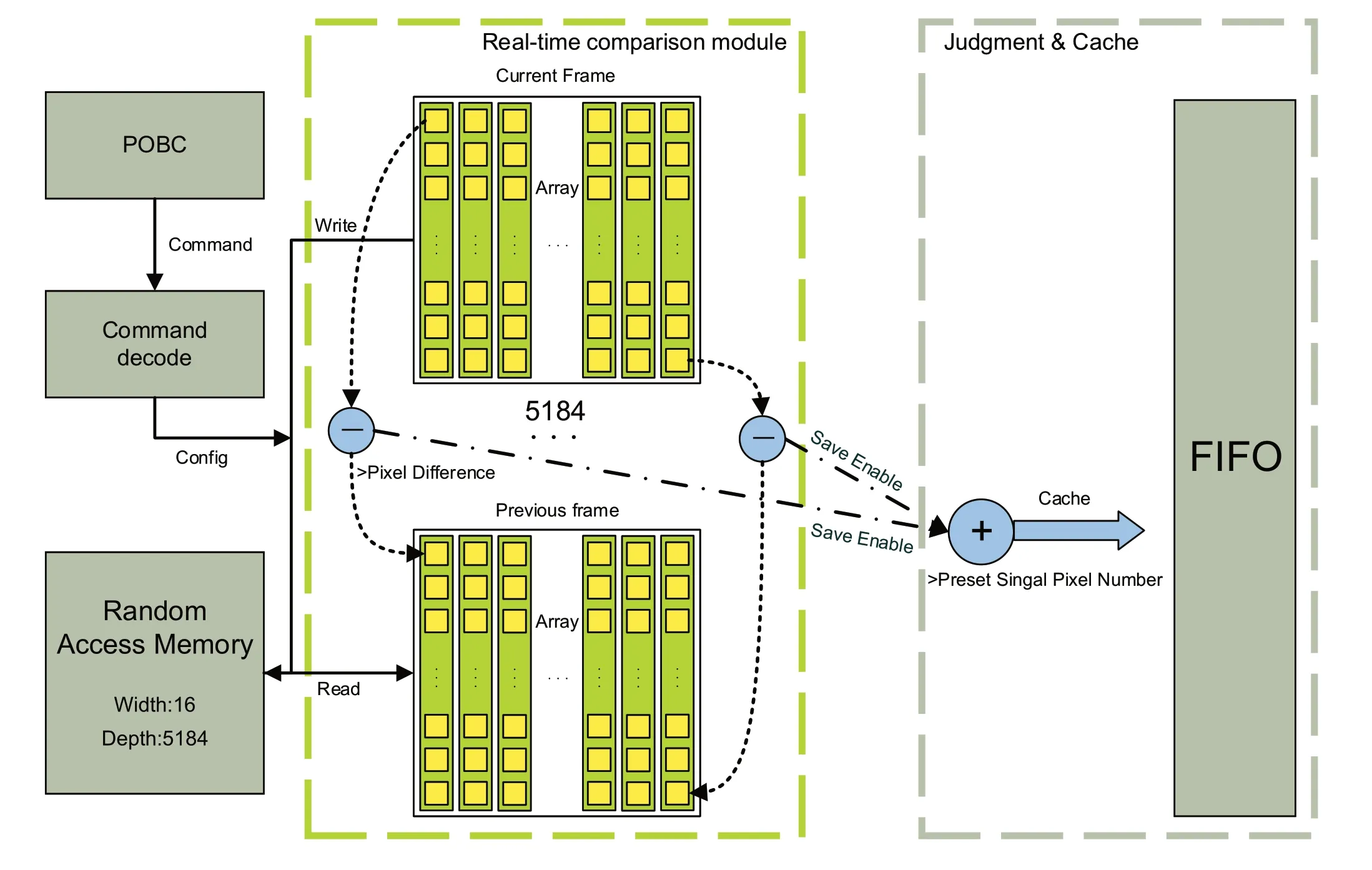
Fig.7 (Color online) DCM works directly with fixed-point integer calculations, and high-speed calculations allow the processing of pixel data in real time

Table 3 Differences in storage methods
The high-voltage boost and buck require time to complete.After setting the high-voltage value, we designed an internal boost and buck logic to complete the boost and buck at 100 V/s.The experimental results are shown in Fig.10.
5.2 High‑speed performance
The GPD data were stored directly in the eMMC on the board and transmitted to the satellite platform when a satellite read command was received.The GPDs data can be stored for up to 75 days because of the cyclic overwrite method of the eMMC.In extreme cases, the Topmetal-II−scanning frequency was 2 MHz, and the maximum data rate was 128 Mbps.We tested the read/write speed of the eMMC at different clock frequencies using a logic analyzer(Fig.11).The eMMC write rate at clock frequencies above 45 MHz satisfied the demand for the GPD maximum data rate.Meanwhile, the Ethernet transmission rate of 20±4 Mbps was determined by the satellite platform.The read rate of the eMMC satisfied the transmission-rate demand of the satellite platform.
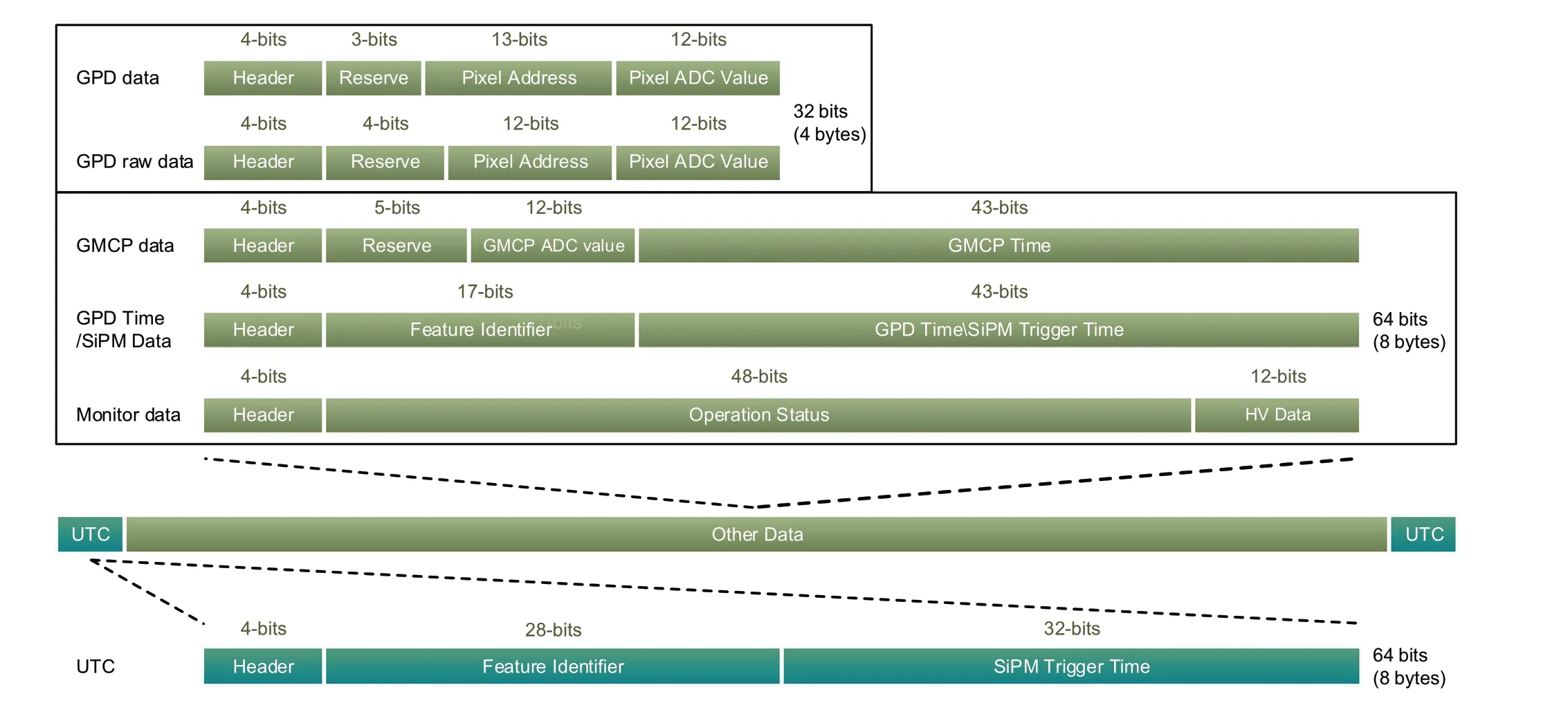
Fig.8 (Color online) Data start with the UTC data after each power on, and the entire data of the measurement mission are between the two UTC data

Fig.9 Top: 5 V input inrush current, bottom: 12 V input inrush current
5.3 Functional test

Fig.10 (Color online) Set the voltage to − 2600 V, and for better display, draw from three seconds before the start to 3 s after the completion of boost and buck
The experimental setup is shown in Fig.12.The external interface of the CXPDES is a custom interface, and we converted the interface to a standard 5.5-mm power round connector, Registered Jack 45, and a CAN bus via a conversion board.
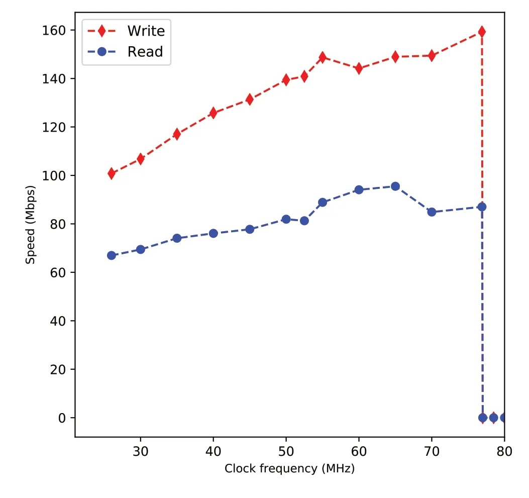
Fig.11 (Color online) Read/write speed taken as average after repeated tests.The eMMC read/write error occurs when the clock frequency is higher than 77 MHz
After powering on the CXPDES, we set it up via the host computer with the parameters listed in Table 4.GPD was started after the setup, and Bragg diffraction was used to generate 8 keV line polarized X-rays for the test.The shutdown command was sent after a period of time to shut down the CXPDES.The above process was repeated, during which the CXPDES devices operated properly, and all commands were executed correctly to obtain the expected feedback.The calibration results from the host computer indicated that all data were transmitted without loss or error.The track image shown in Fig.13 was obtained by offline analysis.The experimental results demonstrate that the electronics system can operate properly and perform X-ray polarimetry missions.
For the stability test, we powered on the electronics system.Tests were conducted for 60 consecutive days without any abnormalities.
6 Discussion and conclusion
In this study, a soft X-ray polarimeter electronics system was described.This system was designed according to the GPD and CubeSat payload requirements, supporting the control and readout of both GPDs with comprehensive and rigorous operational logic.Abundant internal resources and powerful computing capabilities allowed the processing of high-speed data streams by multiple modules and their long-time storage in the CXPDES.Dual-communication channels provided stable and reliable communication.The multiplexed device configuration and status monitoring functioned properly with the ADC and DAC.Moreover, all devices operated correctly from − 40◦to 85◦.We conducted long-term tests on the ground, and the results showed that the system met all the requirements of the CubeSat-based soft X-ray polarimeter.For the difference between the ground test environment and space operation environments, the robustness of the CXPDES was increased using the command to change the parameters and in-orbit upgrade of the electronics system.Future larger-area X-ray polarimeters are already under development, and the CXPD helps resolve possible problems in advance.

Fig.12 (Color online) The 8-mm height adapter pins were used for the test to replace the GPDs, and finally, both GPDs were directly soldered on the FEE board
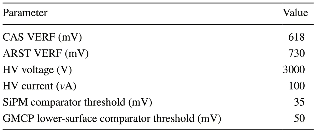
Table 4 Initialization parameters
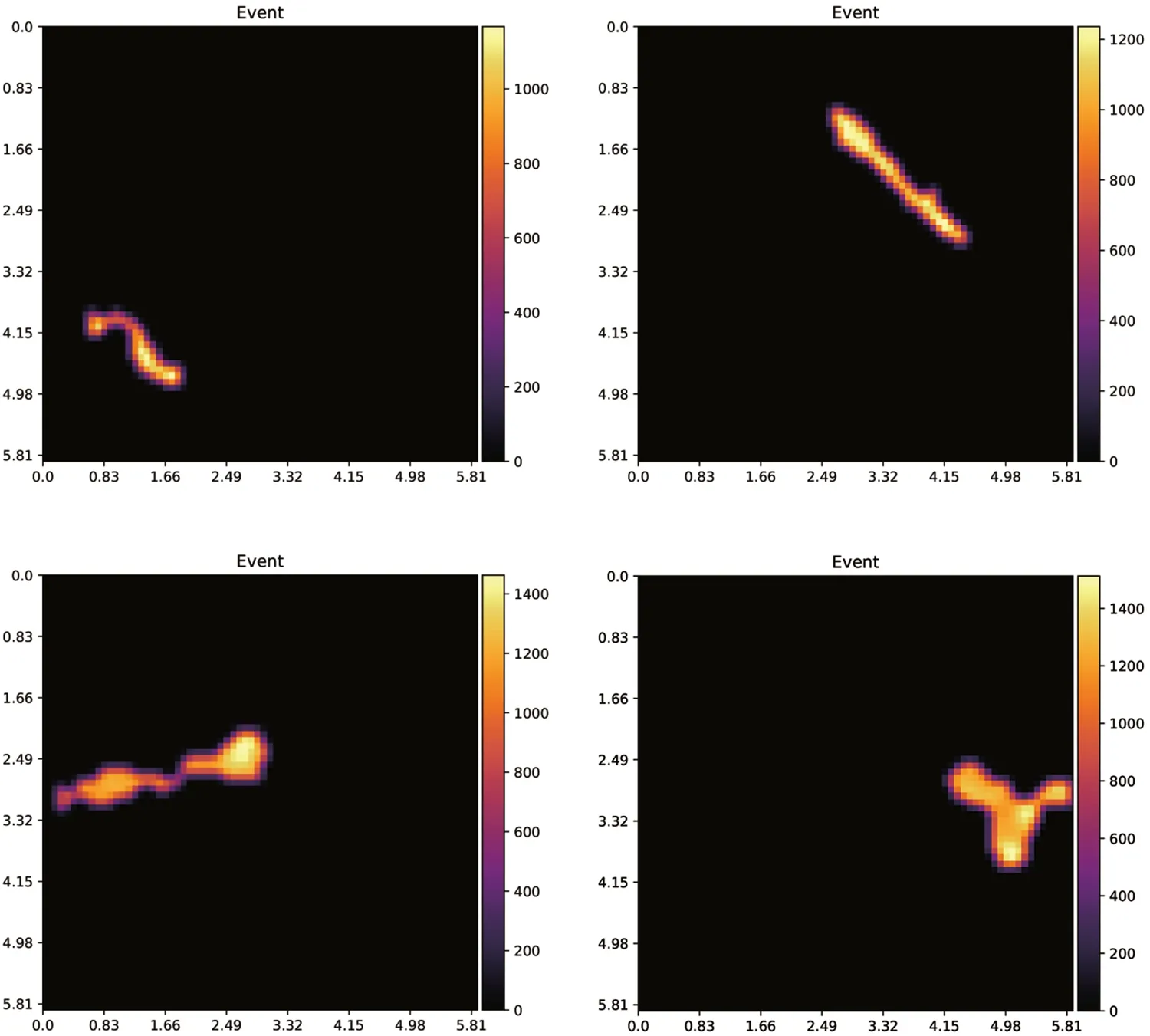
Fig.13 (Color online) 8 keV X-ray tracks
Author ContributionsAll authors contributed to the study conception and design.Material preparation, data collection and analysis were performed by Hui Wang, Ran Chen and Dong Wang.The first draft of the manuscript was written by Hui Wang, and all authors commented on previous versions of the manuscript.All authors read and approved the final manuscript.
Data Availability StatementThe data that support the findings of this study are openly available in Science Data Bank at https:// www.doi.org/ 10.57760/ scien cedb.j00186.00072 and https:// cstr.cn/ 31253.11.scien cedb.j00186.00072.
杂志排行
Nuclear Science and Techniques的其它文章
- GPU‑based cross‑platform Monte Carlo proton dose calculation engine in the framework of Taichi
- Photonuclear production of nuclear isomers using bremsstrahlung induced by laser‑wakefield electrons
- High‑precision high‑voltage detuning system for HIAF‑SRing electron target
- Resolution analysis of thermal neutron radiography based on accelerator‑driven compact neutron source
- Decomposition of fissile isotope antineutrino spectra using convolutional neural network
- Searching for QCD critical point with light nuclei