The effect of controllable train-tail devices on the longitudinal impulse of the combined trains under initial braking
2023-06-14YuanZhangWeiWeiBoyangLiuJunZhangJichaoZhu
Yuan Zhang • Wei Wei• Boyang Liu,2 • Jun Zhang • Jichao Zhu
Abstract The 20,000-ton combined train running has greatly promoted China’s heavy-haul railway transportation capability.The application of controllable train-tail devices could improve the braking wave of the train and braking synchronism,and alleviate longitudinal impulse.However,the characteristics of the controllable train-tail device such as exhaust area,exhaust duration and exhaust action time are not uniform in practice,and their effects on the longitudinal impulse of the train are not apparent,which is worth studying.In this work,according to the formation of the Datong–Qinhuangdao Railway,the train air brake and longitudinal dynamics simulation system(TABLDSS)is applied to establish a 20,000-ton combined train model with the controllable train-tail device,and the braking characteristics and the longitudinal impulse of the train are calculated synchronously with changing the air exhaust time,exhaust area,and action lag time under initial braking.The results show that the maximum coupler force of the combined train will decrease with the extension of the continuous exhaust time,while the total exhaust time of the controllable train-tail device remains unchanged;the maximum coupler force of the combined train reduces by 32.5%with the exhaust area increasing from 70%to 140%;when the lag time between the controllable train-tail device and the master locomotive is more than 1.5 s,the maximum coupler force of the train increases along with the time difference enlargement.
Keywords Controllable train-tail device ∙20,000-ton combined train ∙Coupler force ∙Initial braking
1 Introduction
Heavy-haul railway transportation has been one of the main directions of railway development and has received more and more attentions due to its advantages of low cost,high efficiency,and energy conservation.In China,Datong-Qinhuangdao Railway is the first double-tracked heavy-haul electric coal-dedicated line undertaking Chinese coal resources transportation,and has successfully been operating the 20,000-ton combined train since 2006.As the vehicles continue to use air braking systems and the length of a 20,000-ton combined train is about 2700 m,the asynchronization of each vehicle air braking arises and causes the problem of longitudinal impulse during the train braking.Aiming to reduce the longitudinal impulse during the 20,000-ton combined train braking,the controllable train-tail device was officially utilized in 2007 to exhaust the compressed air at the brake pipe end to improve braking synchronization.For the difference between the controllable train-tail device and the locomotives,the exhaust performance of the controllable train-tail device will affect the vehicle air braking transmission and the longitudinal impulse of the train.Therefore,it is necessary to study the influence of controllable train-tail characteristics on the longitudinal impulse of the 20,000-ton combination train.
Researchers usually adopt experimental and numerical simulation methods to study longitudinal train dynamics.However,the numerical simulation method is widely used because of its high efficiency,low risk,low cost,and ability to conduct multi-parameter influence analysis.Cole et al.[1,2] introduced the important development of longitudinal train simulation and explained the longitudinal train modeling methods,which cover the numerical solver,vehicle draft gear model,traction and dynamic brake model,pneumatic brake model,propulsion resistance,curving resistance,gravitational components,and presented applications of longitudinal train simulation.Wu et al.[3]focused on dynamics models that can be used for freight train air brake simulations,sorted out the 24 braking models,and analyzed the modeling principles of the empirical model,fluid dynamic model,and fluid empirical dynamic model,finally discussed the challenges and research gaps in air braking modeling.Because the longitudinal impulse of heavy haul trains is closely related to the characteristics of their vehicle braking systems,it is necessary to conduct a joint analysis of the train braking system and the train longitudinal dynamics system.Specchia et al.[4,5]established the locomotive automatic brake valve,air brake pipe and vehicle control unit model(CCU),then predicted the train braking performance,and simulated the train dynamics by combining the train longitudinal dynamic model.Aboubakr et al.[6] built up the electronically controlled pneumatic (ECP) brake model including the train line,locomotive automatic brake valve,air brake pipe,and manifold,predicted the longitudinal dynamic characteristics of 50 vehicles,and compared the simulation results with the safety and operation of the American Railway Association and the test results in other references.Pugi et al.[7,8] set up a simplified model of longitudinal train dynamics based on the three-dimensional freight car with the braking model and buffer model,then simulated various working conditions and studied the relationship between train braking characteristics,buffer characteristics,and train formation with longitudinal train impulse.Mohammadi et al.[9,10] established the longitudinal dynamic model of the train by using MATLAB software to discuss the influence of braking system characteristics on the train longitudinal impulse.Many scholars have conducted longitudinal dynamics research in China based on the Chinese braking system and heavy haul trains operation.Chang et al.[11] established the longitudinal dynamics and air braking system model based on the nonlinear equations that obtained the brake pipe pressure distribution by measured data in the brake test,and the longitudinal coupler-force was verified by the 20,000-ton heavy-haul train with a configuration of the locomotive(SS4) +51 vehicles (C80) +locomotive (SS4) +51 vehicles (C80) +locomotive (SS4) +51 vehicles(C80) +locomotive(SS4) +51 vehicles(C80).Sun et al.[12] built up a longitudinal train dynamic model with a buffer model based on the vehicle impact test data and the train brake model using an air brake characteristic multiparameter mathematical method and analyzed the longitudinal dynamics under different line conditions and braking action.Yang et al.[13]set up a dynamic model of the 20,000-ton heavy-haul train in Matlab/Simulink and obtained air braking force according to the brake cylinder’s pressure change curve.The longitudinal impulse of the locomotive (SS4) +102 vehicles (C80) +2 locomotives(SS4) +102 vehicles (C80) +locomotive (SS4) combination train was analyzed by considering the influence of factors such as lag time of the slave locomotive,vehicle type,draft gear device,and operating conditions under emergency braking.Wei et al.[14–18] developed the simulation system TABLDSS by combining the air brake simulation system with the longitudinal dynamics simulation system in FORTRAN to conduct the synchronous simulation of air braking and longitudinal dynamics.In the TABLDSS,the air brake simulation system is based on the air-flow theory,which can reflect the pressure distribution and air brake force under the operation of braking and releasing.It gets rid of the limitation of empirical formulas and numerical interpolation on test results to obtain the air braking force and provides an analysis tool for the influence of the air braking system characteristic on the longitudinal impulse of the train.In the international evaluation of the train longitudinal dynamics simulation system,the TABLDSS simulation system was the one with the fastest calculation speed,better simulation accuracy,and high simulation accuracy among nine simulation systems from six countries [19].
The controllable train-tail device has been used in the 20,000-ton combined train of Datong–Qinhuangdao Railway for many years,relevant studies are few except that Wei et al.[20]studied the effect of train-tail characteristics on the 20,000-ton combined train longitudinal impulse by TABLDSS under full-service braking.According to the driving instruction manual of Datong–Qinhuangdao Railway,the initial braking by 50 kPa reduction operates most frequently,and the fixed pressure reduction in the controllable train-tail device is 50 kPa.Therefore,this work establishes the controllable train-tail device model in the train air braking simulation system that reflects the characteristics of Datong–Qinhuangdao Railway,conducts joint simulation with the train longitudinal dynamics,mainly studies the influence of the exhaust characteristics of the controllable train-tail device on the longitudinal impact of the 20,000-ton combined train under the initial braking of 50 kPa pressure reduction,and provides theoretical reference and analysis tools for the design and improvement of the controllable train-tail device.
2 Train air brake and longitudinal dynamics simulation
The 20,000-ton combination train adopts two locomotives and a controllable train-tail as shown in Fig.1.Through Locotrol technology and GSM-R communication technology,the master locomotive transmits the braking signal to the slave locomotive and the controllable train-tail,then exhausting of multi-locomotive and controllable train-tail is fulfilled during braking,and each vehicle gradually generates air braking force.The longitudinal train dynamic is used to establish motion equations for each locomotive and vehicle and solve their longitudinal motion processes.

Fig.1 The 20,000-ton combination train structure
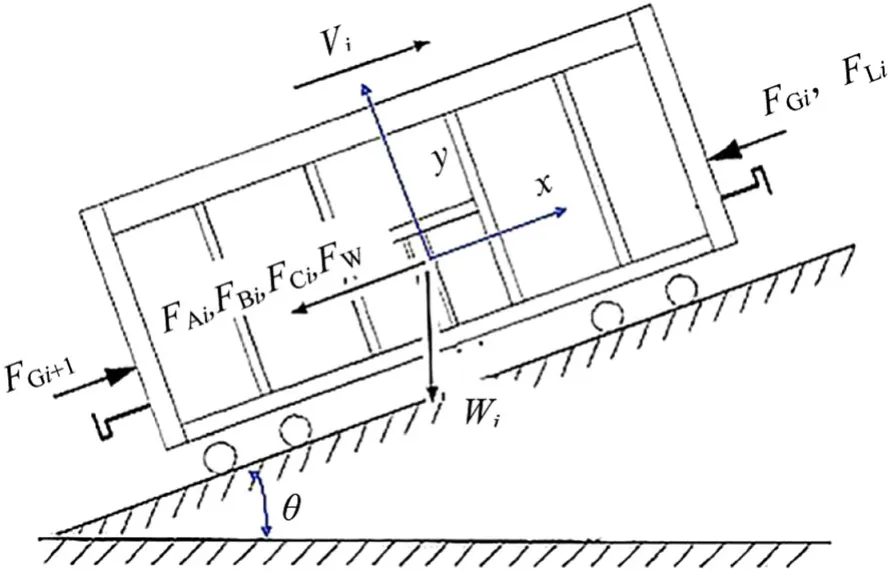
Fig.2 The force diagram of a single vehicle
2.1 Longitudinal dynamics simulation
In the TABLDSS,each vehicle (including the locomotive)is taken as a concentrated mass and has only one longitudinal degree of freedom.Each concentrated mass is connected by a spring-damping system that simulates the coupler and draft gear.Figure 2 illustrates the forces applied to each vehicle.
Each vehicle has the following force equilibrium equation:
whereFGi,FLi,FAi,FBi,FCi,andFWirefer,respectively,to inertia force,coupler force,traction force or electric braking force,running resistance,air braking force,curve resistance and grade resistance;mi,xi,vi,andiindicate vehicle mass,instantaneous position,speed,and serial number,respectively.The curve resistance,grade resistance,and running resistance are calculated by Eqs.(4)–(7) according to Chinese railway standard,Train Traction Calculation (TB/T 1407.1-2018) for both the locomotives and wagons:
whereRrefers to the curve radius;jis the thousands of line gradient;wris the unit curve resistance (N/kN);wiis the unit curve resistance(N/kN);is unit running resistance of vehicle C80 (N/kN);is the running resistance of locomotive HXD1 (N/kN).
The coupling forceFGiis estimated by
where Δxandare the adjacent vehicles’ relative displacement and velocity;KandCrepresent the stiffness and damping of the draft gear obtained in the vehicle impact test.The specific numerical solution is shown in Ref.[15].
2.2 Train air brake simulation
The air braking simulation system calculates the air flow in the braking system at each moment,and then obtains the characteristics of the air braking system according to the air flow theory.When the compressed air flows in the brake pipe,it complies with the conservation equations of energy,momentum,and mass:
whereuis flow velocity;ρ is gas density;pis pressure;Fis cross-sectional area;ais sound velocity;fis the friction coefficient of the inner wall;qis heat transfer rate;kis specific heat ratio;Dis pipe diameter;tis time;andxis distance.The above equations are converted into ordinary differential equations using the characteristic line method.By combining the boundary equations at the boundary nodes,the gas state in the pipeline can be determined.Based on the results,the gas status of the internal valve passage and each cylinder chamber is calculated at each time in the 120-distribution valve model,and the air braking characteristics and air braking forceFBiare obtained.Refs.[21,22] specify the numerical solution process.
The controllable train-tail device can be approximately considered as a braking source,but it is different from the locomotive air exhaust device.It does not maintain the same pressure reduction amount as the locomotive during service braking.No matter how much the locomotive pressure reduction amount is,the pressure reduction amount of the train-tail device is near 50 kPa.Secondly,there is an oscillation phase in the pressure reduction.Based on the principle of the controllable train-tail device,it is modeled as a pipe with a hole at the end,and the boundary Eqs.(10)–(12) are listed below.When the controllable train-tail device starts to exhaust,the train pipe becomes an open end at the tail,Eq.(10) is used as the boundary equation in the gas flow theory to solve the train air flowing state with Eq.(9),and its area is constrained by the train pipe pressure reduction and target pressure reduction according to Eq.(11).When the train tail is closed,Eqs.(12) and (9) solve the train airflow state together.
whereAis dimensionless sound speed;φ is hole area opening ratio,λ is the inlet riemann variable;kis specific heat ratio;φ0is initial area;Δpis pressure drop;and Δp0is pressure drop set value.
As the longitudinal dynamics system and the train air brake system performs co-simulation,the longitudinal dynamic calculation adopts a fixed integration step,while the air braking simulation uses the non-fixed integration step according to the gas flow state.Once the braking system calculation time exceeds the dynamics calculation time,we obtain the air braking force corresponding to the dynamics calculation time by interpolating with the air braking simulation results of this step and the previous step.The calculation process is described in Ref.[15].
3 Simulation analysis of train braking and longitudinal impulse
The 20,000-ton combined train adopts the formation of 1 locomotive(HXD1) +105 vehicles(C80) +1 locomotive(HXD1) +105 vehicles (C80)+the controllable train-tail device.The wagon C80 contains the Chinese 120 distributing valve and the MT-2 type draft gear.Table 1 lists some parameters of the wagon C80 and the locomotive HXD1.The train runs on a flat and straight track at 70 km/h and the brake pipe pressure is 599 kPa.The simulation case is that the combined train is under initial service braking by 50 kPa reduction,and the locomotives do not apply electric braking force.
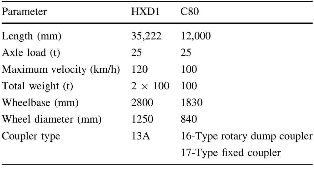
Table 1 The parameters of locomotive HXD1 and wagon C80
3.1 The exhaust time arrangement of the controllable train-tail device
When the combined train applies the initial service braking,the pressure air in the brake pipe discharges through the exhaust of the controllable train-tail device and the locomotives.And the controllable train-tail device and the slave locomotive lag behind the master locomotive for 2 s.Figure 3 is a schematic diagram of the exhaust process of the device.When the controllable train-tail device is working,there are two stages: continuous exhaust and intermittent exhaust.The continuous exhaust can quickly reduce the brake pipe pressure and swiftly generate the braking force of the rear vehicles at the beginning of braking.The intermittent exhaust prevents the brake pipe pressure from rising excessively due to the back surge of pressure air caused by the controllable train-tail deviceclosing.In Fig.3,there are two curves:the red curve is the test data of Datong–Qinhuangdao Railway,and the black curve is the simulation result,and they are very close,where the continuous exhaust time (t1) is 3.4 s,the intermittent exhaust time(t2)is 3.7 s,and the time of one cycle(Δt) during intermittent exhaust is 0.6 s.
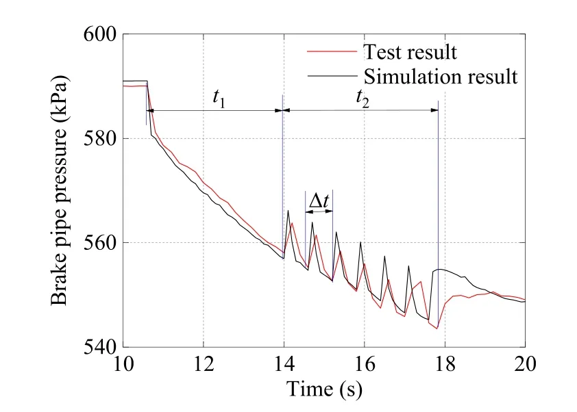
Fig.3 Exhaust time arrangement of the controllable train-tail device
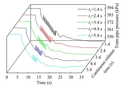
Fig.4 Brake pipe pressure of last vehicle under different exhaust time arrangement
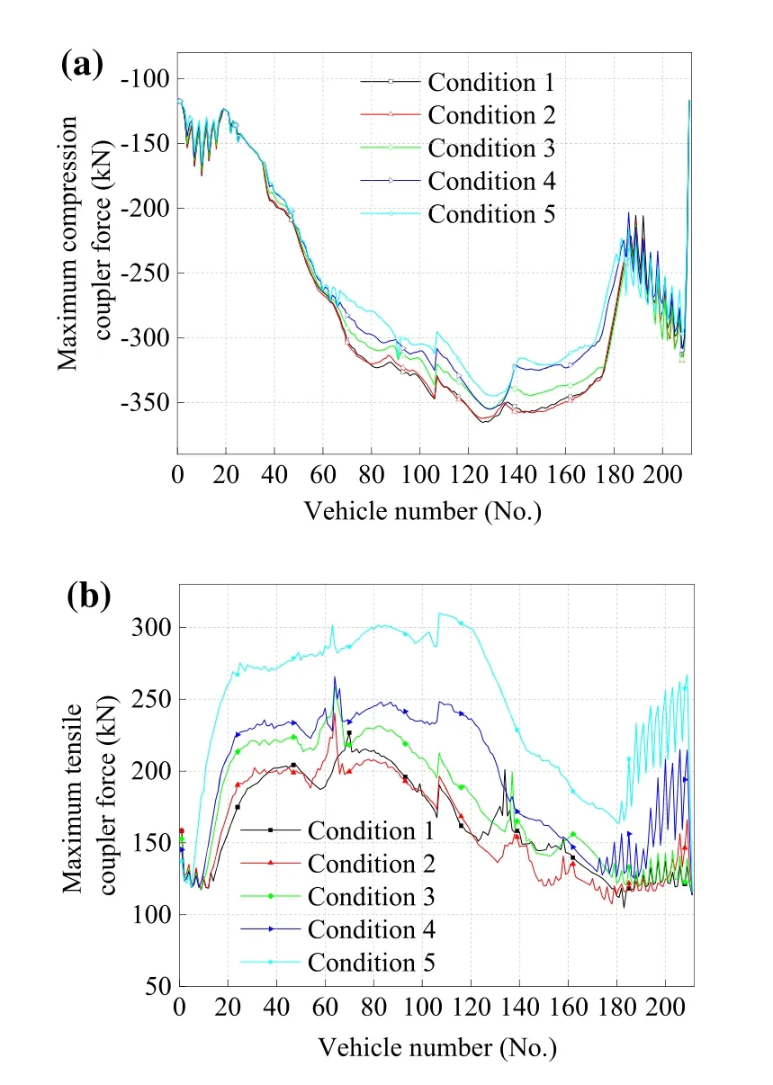
Fig.5 The maximum coupler force distribution of the trains: a the maximum compression coupler force;b the maximum tensile force
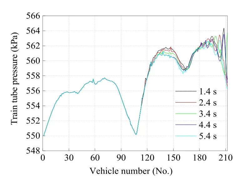
Fig.6 Brake pipe pressure of the last vehicle in the trains
Due to the unstable performance of the controllable train-tail device in practical application,five conditions of continuous exhaust time are set by 1.4,2.4,3.4,4.4,and 5.4 s to simulate the exhaust time fluctuation.Figure 4 shows the brake pipe pressure of the last vehicle in different continuous exhaust time of the controllable train-tail device.The final brake pipe pressure of the last vehicle is 557.51,556.59,556.42,557.06,and 556.21 kPa,respectively,and the maximum pressure difference is only 1.3 kPa.It shows that when the total working time of the controllable train-tail device is constant,the extension of continuous exhaust stage will not increase the pressure reduction of the controllable train-tail device.After the controllable train-tail device is closed,the echo of the brake pipe is,respectively,7.22,6.35,7.32,6.72,and 7.18 kPa under each condition,which does not increase with the shortening of intermittent exhaust time.
Figure 5 shows the distribution of the maximum tensile coupler force and the maximum compression coupler force along the train length.By comparison,the maximum coupler force of the train is the compression force.The maximum compression coupler force mainly occurs between the 120th and 130th vehicle,and the maximum tensile coupler force occurs between the 60th and 80th vehicle except when the continuous exhaust time 5.4 s.
The influence of continuous exhaust time on train braking performance is also analyzed.Figure 6 illustrates the air pressure distribution of the brake pipe along the train,and Fig.7 shows the average pressure of the brake cylinders on the front and rear vehicles when the controllable train-tail device stops exhausting.As shown in the two figures,the continuous exhaust time of the controllable train-tail device has little effect on the pressure distribution of the brake pipe and the average brake cylinder pressure of the first 105 vehicles.While for vehicles behind the slave locomotive,the brake pipe pressure drop accelerates,and the mean brake cylinder pressure increases from 99.33 to 102.29 kPa.With the continuous exhaust time of the controllable train-tail device prolonging,the braking capacity increases and the impact effect weakens.

Fig.7 Average values of brake cylinder pressures at the front and rear vehicles of the trains
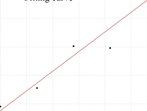
Fig.8 Relationship between exhaust mode and maximum coupler force
From the above analysis,it can be seen that the time allocation of the controllable train-tail device has an effect on the train braking characteristics,which in turn affects the longitudinal impulse of the train.Figure 8 shows the relationship between the continuous exhaust time proportion of the controllable train-tail device and the maximum coupler force of the train.As the continuous time increases,the max coupler force of the train decreases.The linear fitting result of the changing trend is shown in Eq.(13),and the equation has some values for the maintenance and design improvement of the controllable train-tail device for reducing the longitudinal impulse of the train.
whereFmaxis the maximum compression coupler force of the train in kN,andxis the ratio of the continuous exhaust time to the total time of the controllable train-tail device.
3.2 Exhaust hole area of the controllable train-tail device
The controllable train-tail device is a single-hole exhaust mechanism,and the area affects the pressure change of the brake pipe during braking.According to the test results,the initial exhaust hole area φ0of the controllable train-tail device model is determined,and then a proportion coefficient is used to simulate the initial exhaust hole area changing from 70% to 140% with an interval of 10%.In the following simulation under the train initial braking by 50 kPa reduction,the action time difference between the locomotives and the controllable train-tail is 2 s,and the exhaust time distribution of the controllable train-tail is shown in Fig.9.
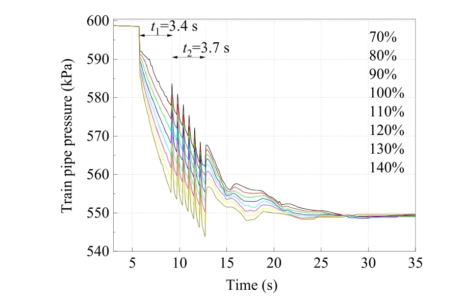
Fig.9 Brake pipe pressure of the last vehicle under different exhaust area

Fig.10 Braking wave transmission of the train
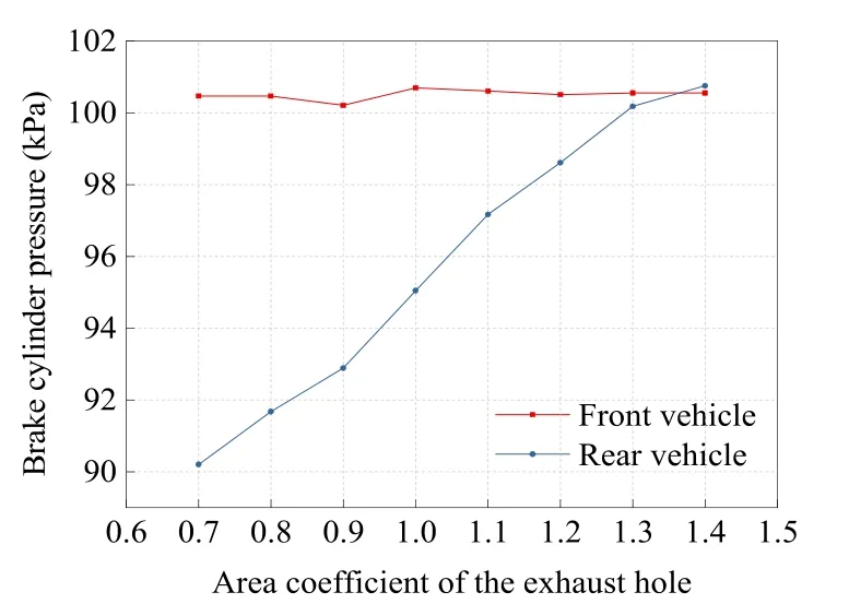
Fig.11 Average values of brake cylinder pressures at the front and rear vehicles of the trains
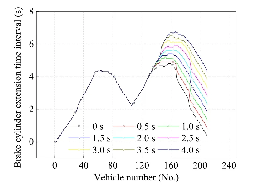
Fig.12 Braking wave transmission by different delay time of the controllable train-tail device
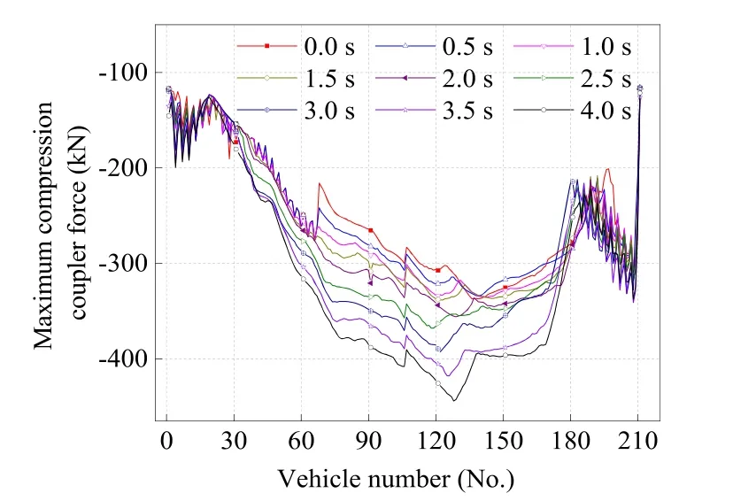
Fig.13 Maximum compression coupler forces of trains with different lag time
Figure 9 shows the brake pipe pressure changing at the last vehicle with different exhaust hole areas of the controllable train-tail device.It can be seen that the brake pipe pressure drops more rapidly with the expanding exhaust area.When the controllable train-tail stops exhausting,the brake pipe pressure reduction of the last vehicle is less than 50 kPa with the exhaust area coefficient changing from 70% to 110%,and exceeds the target value of 50 kPa when the exhaust area coefficient is in the range of 120–140%.
Figure 10 shows the braking wave transmission of the train when the controllable train-tail has different exhaust areas.As the exhaust area increases,the braking wave of the rear vehicles is faster and the braking synchronization of the train improves.Figure 11 shows the average pressure of the brake cylinder of the front vehicles and rear vehicles at the 20 s after braking.As the exhaust hole area of the controllable train-tail device increases,the braking capacity of the rear vehicle increases,and the average pressure difference of the brake cylinders at the front and rear vehicles decreases from 10.2 to 0.20 kPa.
Table 2 lists the maximum compression coupler force,the maximum tensile coupler force,and the corresponding vehicle position in the train.The compression force of the train is greater than the tensile force,and the maximum compression force of the train decreases as the exhaust hole area increases.When the area coefficient of the exhaust hole enlarges from 70% to 140%,the maximum coupler force of the train decreases by 32.5%.The attenuation in the longitudinal train impact is due to the improvement of braking synchronization by changing the exhaust hole area of the controllable train-tail device.
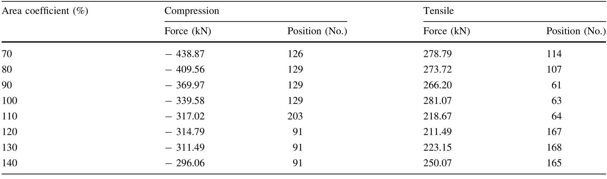
Table 2 The maximum coupler force of the train
3.3 Operation time of the controllable train-tail device
The 20,000-ton train of the Datong–Qinhuangdao Railway adopts Locotrol technology to achieve the synchronous operation of locomotives and reduce the longitudinal impulse of the train.However,the asynchrony of the master and slave locomotive operations still exists with a lag time of 2–3 s generally.The communication lag time between the controllable train-tail device and the locomotive is no more than 0.8 s,and the total response time is no more than 1.5 s [23].Therefore,the influence of the exhaust inconsistency between the locomotive and the controllable train-tail on the longitudinal impulse will be discussed.The conditions are that the slave locomotive lags behind the master locomotive for 2 s,and the lag time of the controllable train-tail behind the master locomotive increases from 0 to 4 s with an interval of 0.5 s.
Figure 12 illustrates the braking wave transmission of the train under the different lag times of the controllable train-tail device.The average action time of the brake cylinder pistons of front vehicles between the master and slave locomotives is 2.8 s,while the average action time of the rear vehicles increases from 3.2 to 5.1 s with the lag time rising.Accordingly,the braking wave transmission slows down,and the braking synchrony of the front and rear vehicles reduces.
Figure 13 shows the distribution of the maximum coupler force of the train.During the braking process,the maximum coupler force of the train is the compression force.When the controllable train-tail device lags 4 s,the maximum coupler force is 443.99 kN;when the controllable train-tail device and the master locomotive act synchronously,the maximum coupler force is only 337.10 kN.Hence,the maximum coupler force decreases by 31.7%with the lag time shortening.
Figure 14 shows the relationship between the maximum coupler force of the train and the lag times of the controllable train-tail device when the slave locomotive lags the master locomotive for 2 s and 3 s.The maximum coupler force of the train is a compression force during braking.In Fig.14,the relationship has two stages: when the controllable train-tail lags behind the master locomotive within 1.5 s,the maximum force is small and changes a little,but when the lag time exceeds 1.5 s,the maximum force increases significantly.Equations (14) and (15)describe the correlation between the lag time of the controllable train-tail and the maximum coupler force when the slave locomotive lags the master locomotive for 2 s and 3 s,respectively.The simulation results provide a theoretical basis for adjusting the action time of the controllable train-tail device from the perspective of reducing the longitudinal impulse of the train.

Fig.14 Relationship between lag time and maximum coupler force
whereFmaxis the maximum compression force of the train in kN,andtis the lag time of the controllable train-tail device.
4 Conclusion
In this work,we establish the controllable train-tail device model according to the performance of Datong–Qinhuangdao Railway,apply the TABLDSS simulation system to calculate the maximum coupler force of a 20,000-ton combined train with different continuous exhaust time,exhaust areas,and action lag time of the controllable traintail device under initial braking by 50 kPa reduction in brake pipe pressure,and analyze the influence of controllable train-tail device characteristics on longitudinal train impulse.The following conclusions are obtained:
1.When the total exhaust time of the controllable traintail device is fixed,the maximum coupler force of the combined train decreases with the increase in the continuous exhaust time.The maximum coupler force was cut down by 5.6% when the continuous exhaust time was 5.4 s compared with 1.4 s.
2.With the increase in the controllable exhaust area of the train-tail device,the maximum coupler force of the train decreases.When the exhaust area coefficient at the controllable train-tail device increases from 70%to 140%,the maximum coupler force is reduced by 32.5%.
3.When the lag time between the controllable train-tail device and the main control locomotive is within 1.5 s,the maximum coupler force of the train changes little;and the lag time exceeds 2 s,the maximum coupler force of the train rises by 31.7% with the lag time increase.
AcknowledgementsThis work was supported by China National Railway Group Co.,Ltd (N2020J037).
Open AccessThis article is licensed under a Creative Commons Attribution 4.0 International License,which permits use,sharing,adaptation,distribution and reproduction in any medium or format,as long as you give appropriate credit to the original author(s) and the source,provide a link to the Creative Commons licence,and indicate if changes were made.The images or other third party material in this article are included in the article’s Creative Commons licence,unless indicated otherwise in a credit line to the material.If material is not included in the article’s Creative Commons licence and your intended use is not permitted by statutory regulation or exceeds the permitted use,you will need to obtain permission directly from the copyright holder.To view a copy of this licence,visit http://creativecommons.org/licenses/by/4.0/.
杂志排行

Railway Engineering Science的其它文章
- A numerical method for the simulation of freight train emergency braking operations based on the UIC braked weight percentage
- Influence of quick release valve on braking performance and coupler force of heavy haul train
- A simplified pneumatic model for air brake of passenger trains
- Braking distance prediction for vehicle consist in low-speed on-sight operation: a Monte Carlo approach
- An approach for simulating the air brake system of long freight trains based on fluid dynamics
- HIL testing of wheel slide protection systems: criteria for continuous updating and validation