Influence of quick release valve on braking performance and coupler force of heavy haul train
2023-06-14WeiWeiYuanZhangJunZhangXubaoZhao
Wei Wei• Yuan Zhang • Jun Zhang • Xubao Zhao
Abstract We establish a simulation model based on the theory of air flow to analyze the accelerated release effect of the quick release valve inside the air brake control valve.In addition,the combined simulation system of train air brake system and longitudinal train dynamics is used to analyze how the parameters of the quick release valve in the 120/120–1 brake control valve affect the propagation characteristics of the train brake pipe pressure wave,the release action range of the accelerated brake,and the longitudinal coupler force for a 20,000-ton heavy haul train on the section of the Datong–Qinhuangdao Railway.The results show that the quick release valve can effectively accelerate the rising speed of the train brake pipe pressure during the initial release,as the accelerated release effect is evident before the train brake pipe pressure reaches 582 kPa.The quick release valve can effectively accelerate the release of the rear cars,reducing the longitudinal coupler force impact due to time delay of the release process.The quick release valve can effectively reduce the tensile coupler force in the train by as much as 20% in certain cases.
Keywords Brake system ∙Release characteristics ∙Quick release valve ∙Coupler force ∙Heavy haul train
1 Introduction
The quick release valve is designed to accelerate the release of the train air brake system during the release process.The quick release valve in the 120/120–1 brake control valve follows the principle that when the brake control valve is in the release position,the brake cylinder pressure pushes the quick release piston,and an air flow passage from the quick release reservoir to the train brake pipe is formed.The high-pressure air in the quick release reservoir flows to the train brake pipe to increase the pressure of the train brake pipe.This speeds up pressure propagation along the train brake pipe to the cars in the rear of the train,allowing the cars to move into the release position quicker.
The Daqin Railway and Shuohuang Railway have the two most crucial heavy haul freight lines in China.They are the only two lines in China that run 20,000-ton heavy haul trains thus far.Each of these two heavy haul lines has two sections of 50 km of long descending grades,which are the most challenging sections for train operation.In these two sections,cycling air braking between applying brake and releasing is required.Taking the first long descending grade section on the Datong–Qinhuangdao Railway as an example,operating the train in this section requires applying and releasing the brake four times (one brake application and release cycle is counted as one time).During the release process,the coupler longitudinal force is usually high,which has resulted in several accidents due to the couplers broke apart after the release of the first brake application.
In recent years,China’s heavy haul railway has experienced many abnormal releases during braking,and it brings great harm to the safety of heavy haul transportation.Accelerated release function is considered as the possible cause of abnormal release,and the appeal of canceling the accelerating release valve even appears in China.Researches on the accelerated release function through conducting experiments on actual trains are expensive and have high risks.It is therefore advantageous to use simulation models to perform the analyses to predict operation results.
Since the 1970s,USA,India,Italy,China,Brazil,Australia,and other countries have carried out researches on air brake systems based on the theory of air flow [1–8].The simulation model of the air brake system can help solve the problem of obtaining the braking load with consideration to the longitudinal impact force within the train,and reduce the reliance of obtaining the characteristics of the braking system through traditional experimental method.Compared with the experimental method,the simulation method has a wide range of applications and it can be applied to the acquisition of brake system load with various train configurations and brake and release characteristics.It also can perform the continuous simulation of multiplecycle braking of the train on long and steep slopes.Currently,some countries have introduced the simulation of the air brake system into the longitudinal train dynamics[9–12].Wu et al.[13] assessed the implications of wagon pack sizes during train starting,speed correction braking,emergency braking and whole-trip train operations.Saeed and Reza[14]studied the effect of change in draft gear key parameters such as stiffness,damping and clearance,on longitudinal in-train forces during brake application.Cantone and Arcidiacono [15] discussed the influence of charging and discharging characteristics of brake cylinder on in-train forces,and proposed a new safe and economical driving strategy just after brake release.Aboubakr and Shabana[16]investigated the effect of brake-delay time on the in-train forces.Cruceanu et al.[17] simulated the influence of the filling characteristics of the brake cylinder on the longitudinal force of the train,and found that the filling characteristics of the brake cylinder affect the maximum forces and their distribution in the vehicles along the train.Wei’s team [18,19] studied the influence of the local reduction in the first and second stages of the brake control valve on the longitudinal dynamics,and the effect of a time delay of the controllable exhausting device installed on the tail (last) car on the longitudinal impact.
For different simulation purposes,the simulation model precision for the train air brake system is different.For instance,the pipeline model is established based on airflow theory,and the brake valve model of the car is calculated by empirical formulas.In other cases,the models utilize the valve internal structure,operation principle,force condition of the moving parts to calculate the air passages and orifice areas.These precision models can be used to analyze the influence of the control valve parameters of the air brake system on the braking performance and the longitudinal coupler forces of the train.
Research on the correlation between air brake systems and longitudinal dynamics of heavy haul trains has always been a highlight in brake system design and longitudinal dynamics.The longitudinal impact plays an important role in future design of the air brake system for heavy haul trains.However,due to the difficulty of establishing a precision air brake system model and the combined simulation of the air brake system and longitudinal dynamics,the correlation between the train air brake system and longitudinal dynamics has not been fully understood.
TABLDSS is a combined simulation system of air brake system and longitudinal dynamics of trains.The simulation system received excellent score in the evaluation of International Benchmarking of Longitudinal Train Dynamics Simulators [20].The simulation system performs a synchronous simulation of the air brake and the longitudinal train dynamics.The simulation system models the locomotive automatic brake valve and car brake control valve [21],involving the critical parameters of the car brake control valve,such as spring forces,flow orifice areas in the valve.In simulation,instructions to control the train operation are input with a computer,as if a train operator drives a train.It also can use the actual train operation data to reproduce the train operation process and calculate the longitudinal dynamic performance of various trains.Currently,the simulation system has been widely used by the Daqin Railway and Shuohuang Railway in China.It has also been successfully applied to the derailment analysis in the Daqin Railway in 2020.It is a useful tool for analysis of accidents,optimization of operation methods,and analysis of daily complicated problems in the aforementioned two heavy haul railroads.
2 Simulation principle of air brake system and longitudinal dynamics
TABLDSS is a combined simulation system,which mainly includes brake system simulation model and train longitudinal dynamics simulation model.These two models are introduced below.
2.1 Air brake system model
The basic principle of the simulation of the air brake system is to calculate the unsteady flow process of compressed air in the air brake system,especially the airflow in the brake pipe.The basic equations are as follows:
where ρ,u,p,a,k,D,F,f,q,x,andtdenote the air density,flow velocity,pressure,sound velocity,specific heat ratio,pipe diameter,cross-sectional pipe area,the friction coefficient of the inner wall of the pipe,heat transfer rate,distance,and time,respectively.The basic equations of airflow in the pipe and various boundary equations constitute the basic framework of the simulation of the train air brake system.For boundary equations used in the brake system model,one can refer to Ref.[21].
This paper mainly discusses the impact of the quick release valve on the braking performance and the longitudinal impact of the train.To this end,the quick release valve model and its mechanism are discussed in detail.
The car brake control valve model is shown in Fig.1.There are nine variable orifices in the brake control valve of each car.The orifice status and their areas are determined according to the force and position of the moving parts in the brake control valve.When braking is over,the train operator puts the automatic brake handle of the locomotive in the release position,and the locomotive first charges air to the equalizing reservoir[21].The relay valve allows charging from the locomotive main reservoir to the train brake pipe according to the pressure difference between the equalizing reservoir and the train brake pipe.As the train brake pipe is being charged,the pressure of the train brake pipe increases.In Fig.1,the brake branch pipe is always connected to the upper chamber of the main valve,which means that the pressure of the upper chamber of the main valve is almost equal to the pressure of the train branch pipe.The pipe of the auxiliary reservoir is always connected to the lower chamber of the main valve,and the pressure of the lower chamber of main valve is almost equal to the pressure of the auxiliary reservoir.
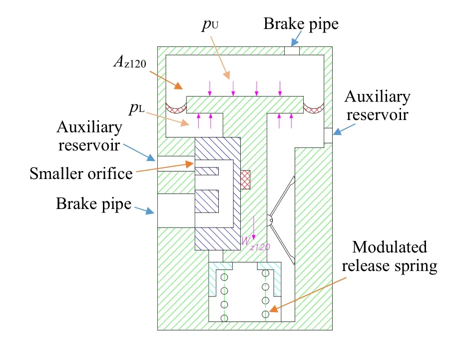
Fig.2 Piston at modulated release position
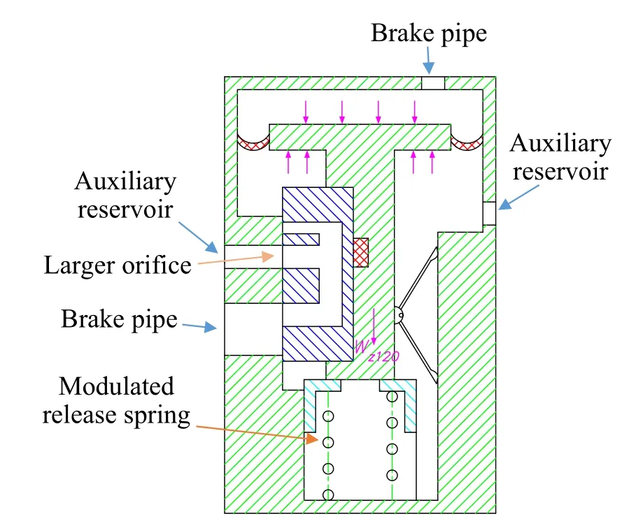
Fig.3 Piston at release position
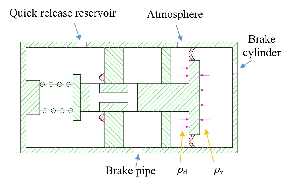
Fig.5 Quick release valve orifice opened
During release,the main valve may be in the modulated release or release position.The position diagram of the main valve piston in the brake control valve is shown in Figs.2 and 3.
The piston of the brake control valve position is calculated according to
wherepUandpLare the instantaneous pressures of the upper and lower chambers of the main valve,respectively;Az120is the effective area of the main valve piston;Wz120is the weight of the main valve piston;Fh120his the release resistance of the main valve,andFjyg120is the working force of the modulated release spring.
Equation (2)indicates the conditions for the main piston of the brake control valve.When the sum of the forces acting on the piston caused by the pressure difference between the upper and lower chambers and the gravity is greater than the sum of the release resistance of main valve and the working force of the modulated release spring,the main piston of the control valve enters the modulated release position.This is a condition in which the releasing is normal,but the air charging from the brake pipe air to the auxiliary reservoir is through a smaller orifice in the brake control valve.When the sum of the forces acting on the main piston and the gravity of the main piston is only greater than the release resistance of the main valve,the main piston enters the regular ‘‘release position’’.This is a condition in which the releasing is normal,but the air charging from the brake pipe to the auxiliary reservoir is through a larger orifice in the brake control valve.The purpose of such design in the brake control valve is to allow slower charging to the auxiliary reservoirs on the cars in the front of the train and faster charging to the auxiliary reservoirs on the cars in the rear of the train.
When the main piston is in the modulated release position or the release position,it remains in these positions under the following conditions:
The position diagram of the piston in the quick release valve is shown in Figs.4 and 5.
When the main valve is in the modulated release position or the release position,the quick release valve orifice is determined according to the following conditions:
wherepzandpdare the instantaneous pressure of the brake cylinder and atmosphere,respectively;Aj120is the effective area of the piston of the quick release valve,andFjs120is the working force of the quick release valve spring.When the force acting on the quick release piston is greater than the working force of the quick release valve spring,the quick release valve opens the passage between the quick release reservoir and the brake pipe.
When the main piston is in the modulated release position or the release position,Eq.(4)indicates that when the pressure of the brake cylinder is at a specific value,the quick release valve will work and the accelerated release effect will occur.When the quick release valve is opened,the airflow from the quick release reservoir will enter the upper chamber of the main valve through internal passage in the control valve.When this occurs,the pressure of the train brake pipe will rise,accelerating the subsequent cars to entering the release position.To simplify the simulation model,it is assumed in the model that if the quick release valve is opened,the air in the quick release reservoir passes through the virtual orifice φ7to flow into the upper chamber of the main valve.The virtual orifice mainly simulates the equivalent orifice of the accelerated release passage in the valve.Therefore,it is assumed that the quick release reservoir is upstream,and the upper chamber of the main valve is downstream.The two are connected through a small orifice.The mass flow rate is calculated using the following model:
wheref(M) is calculated by
Mis the Mach number,calculated by
φ7is the equivalent orifice area of the accelerated release passage in the valve,and the value is determined by empirical data;pjis the instantaneous pressure of the quick release reservoir;kis the specific heat ratio of the air;A0is the dimensionless stagnation speed of sound.It should be noted that when the accelerated release function occurs,the air mass flow rate changes continuously with the pressure of the train brake pipe and the quick release reservoir.After obtaining the air mass flow rate at each moment,the instantaneous static air states of the quick release reservoir and the upper chamber of the main valve can be obtained.
2.2 Longitudinal dynamics model
The longitudinal dynamics model of the train treats each individual locomotive and car as a single lumped mass.The connections between each car use spring damping elements.The locomotive or car model is shown in Fig.6,and the longitudinal dynamics equation of the train is as follows:

Fig.6 Longitudinal dynamic model of single car
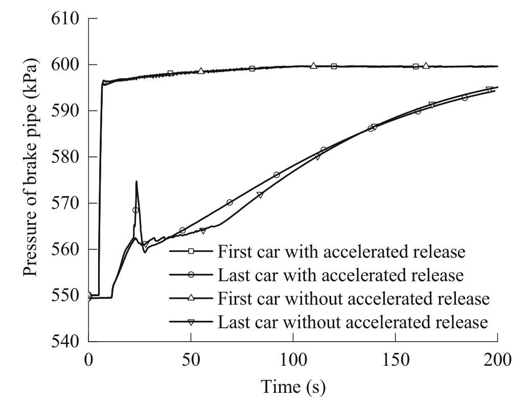
Fig.7 Train brake pipe pressures of the first car and last car with or without accelerated release (simulation results)
wherexi,vi,andWiare the instantaneous position,speed,and gravity of theith car,respectively;FGi,F1i,FAi,FBi,FCi,andFWirefer to the instantaneous inertia force,coupler force,traction or electric braking force,running resistance,air braking force,curve resistance,and ramp resistance of theith car.The physical state of each car in the train can be obtained by solving these sets of equations at every moment.
The above equations have an implied assumption that the train cannot move when there are only non-active forces such as air braking and running resistance.These assumptions are essential,which avoid the possibility of the train running in the opposite direction due to the air braking force or resistance,when the train speed approaches zero.
3 Simulation results and analysis
Currently,China’s heavy haul trains are 20,000-ton trains.The train configuration is 1 loco +105 cars +1 loco +105 cars +controllable exhausting device on the last car.HXD1is the locomotive model,and C80Bis the freight car model.At present,the most dangerous working condition of China’s 20,000-ton train on the Datong–Qinhuangdao Railway is the release during cycling between brakings and releases,which is the release after the brake of reducing the train brake pipe pressure by 50 kPa.In this paper,the influence of the accelerated release effect of the control valve in the release process is analyzed in terms of the above worst working condition.In calculation,the first braking/release cycle is selected,that is,the release after the braking (reduction in train air brake pipe pressure of 50 kPa).To eliminate the influence of the line grade and better understand the accelerated release effect,the flat straight track line is selected.The release after the brake pipe air pressure reduction of 50 kPa for 60 s is taken as an example.If there is no accelerated release function,the effective areaAj120of the quick release valve piston is set to zero.When the effective area of the piston is zero,the conditions for the quick release valve passage in Eq.(4)cannot be met.That is,the accelerated release hole φ7always equals zero.Figure 7 shows the change in train brake pipe pressure during the release process with or without the accelerated release function.In the figure,the pressures of the brake pipe of the first and the last car in the train are plotted.To verify the simulation results,the site experiment results of the train brake pipe pressure of the last car,with accelerated release,of the same train configuration and operation method are plotted in Fig.8.
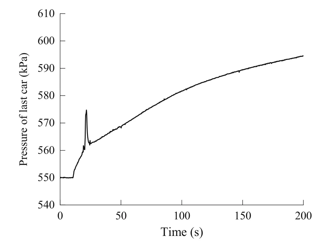
Fig.8 Train brake pipe pressure of the last car with accelerated release (actual test results)
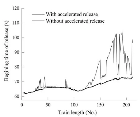
Fig.9 Release starting time of each car with or without acceleration release

Fig.10 Brake cylinder pressure in the first and last car with or without accelerated release
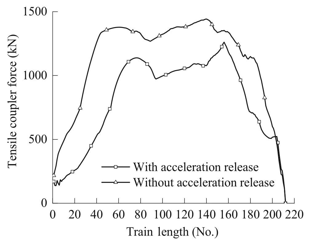
Fig.11 Train coupler tensile force with or without accelerating release

Fig.12 Coupler forces with or without accelerated release in the 150th car
It is shown in Figs.7 and 8 that after the release,the pressure of the brake pipe has a noticeable jump.Before the pressure jump,the pressure of the brake pipe starts to rise by about 10 kPa before the release.The simulation results are consistent with the site experiment results during this initial pressure rise.After the release,the pressure jump of the train brake pipe is about 13 kPa;the simulation results agree well with the experiment results.After the pressure of the train brake pipe increases,the pressure then drops.The drop range of the test result is about 12 kPa,and the corresponding simulation result is slightly larger,about 13 kPa.At 200 s,the pressure of the brake pipe on the last car reaches 594 kPa in the simulation and the test results show similar pressure.From the point of the brake pipe pressure of the last car,the simulation model has a good agreement with the experimental results with respects to the accelerated release strength and train air recharging capacity.Under the condition that the simulation model is reliable,the effect of the accelerated release function is analyzed below.
There is no pressure increasing and then falling back quickly of the brake pipe on the first car in Fig.7,which indicates that there is no accelerated release for the first car due to the strong air recharging capacity of the locomotive.This phenomenon is entirely consistent with the knowledge that the farther away from the locomotive,the stronger the accelerated release effect.After release,the pressure of the brake pipe on the first car increases rapidly,which is entirely different from that of the last car of the train.For the last car,after the handle of the locomotive is placed in the release position,the pressure of the train brake pipe begins to increase slowly.When the pressure of the train brake pipe increases to a certain extent,the car control valve enters the release position,and then the pressure of the train brake pipe has a significant jump and drop.The time when the control valve enters the release position can be seen from the pressure change in the brake pipe pressure in the last car,but the first car does not have such a noticeable pressure change.
The pressure of the brake pipe in the first car rises quickly to a higher level and then increases slowly.For the last car,within the period of the locomotive handle placing in the release position (10 s) and the control valve releasing,the pressure of the train brake pipe rises but at a speed that is much slower than that of the first car.After the control valve in the last car enters the release position,the pressure of the brake pipe will rise and fall instantaneously.Overall,the pressure of the train brake pipe on the last car increases at a slow speed,which is closely related to the air charging capacity of the locomotive,the length of the train,and the leakage of the train brake pipe.Under the simulation conditions (the locomotive air charging capacity,certain leakage,and 20,000-ton train length),the pressure of the brake pipe in the last car rises from the start of the locomotive release to 580 kPa (generally considered as creating a full release) in 109.6 s.
With regard to the pressure of the brake pipe in the last car with or without accelerated release function,there is a noticeable difference in the air charging speed of the brake pipe below 582 kPa,in addition to the significant difference in the pressure jump and drop of the brake pipe in the area of accelerated release.Below 582 kPa,the brake pipe pressure without accelerated release is significantly lower than the corresponding pressure of the car with accelerated release,which is the effective result of accelerated release.It is the consequence of the quick release reservoir feeding air to the brake pipe.When the pressure of the train brake pipe is higher than about 582 kPa,the accelerated release function is completed.After this point,the locomotive simultaneously charges the brake pipe,the auxiliary reservoir,and the quick release reservoir;for the cars without the accelerated release function,the brake pipes will be charged a bit faster because the locomotive needs not to charge the quick release reservoirs.
The brake pipe in the last car without accelerated release function is charged relatively quickly in the initial 8 s,but the brake pipe pressure does not rise high enough to cause a release in this period.After that,the brake pipe pressure increases slowly.At 55 s into this slow charge period,the car brake enters to release position.The brake pipe pressure continues to rise steadily thereafter.
Figure 9 shows the exhaust starting time of brake cylinder in each car with or without accelerated release.The release starting time is not affected by whether there is accelerated release ability or not before the 26th car and between the 96th–122th cars,i.e.,these cars are near the locomotives.Outside these two regions,there is a difference in the starting exhaust time of cars.The difference is less significant for the cars between the two locomotives and more evident for the car after the slave control locomotive.Generally,the role of accelerated release capability is that the weaker the air-charging capability of the car,the stronger the accelerated release effect.Even for a train that has the accelerated release function,the pattern of release time is not consistent as releases on some cars are significantly later than that of the adjacent cars.By analyzing the data,it is found that these cars release later due to the higher pressure of the auxiliary reservoir than the adjacent cars before the release.The reason for this phenomenon is that at the end of a braking application,the brake control valve constantly changes between the brake and lap positions.Before the release,the car control valve enters the lap position at different times.Some cars have been in the lap position for a long time,and some for a short time,resulting in different pressures of the auxiliary reservoir before the release.
Compared with trains with the accelerated release function,except for the cars near the locomotive,trains without the accelerated release function need more time to enter the release position.Some cars even delay the release time by about 30 s.It is found that in general,a car with a lower initial pressure of the auxiliary reservoir starts to release earlier,compared to a car with a higher initial pressure of the auxiliary reservoir.For the cars without the accelerated release function,the release time difference caused by the pressure difference of the auxiliary reservoir is more significant than that of trains with the accelerated release.It means that accelerated release can dramatically reduce the difference in release time caused by the pressure difference of the auxiliary reservoir before the release.
Figure 10 shows the brake cylinder pressures of the first and last cars,with and without accelerated release.As shown in this figure,there is no difference between the first car with accelerated release and that without accelerated release.But for the last car,the one without accelerated release experiences a delay of release by approximately 21 s.The exhausting rate of the brake cylinder air is similar between the car with accelerated release and the car without it.When the brake cylinder pressure is at approximately 13 kPa,the plateaus signify a process that the pistons inside the brake cylinders transition from the extended position to the contracted position.
Figure 11 shows the distribution of the maximum tensile coupler force along the train length with or without the function of accelerated release.Because the compression coupler force is less than the tension coupler force during the release,only the maximum tension coupler force is plotted in the figure.The figure shows the maximum tensile coupler force of each car during the release process.
Figure 11 shows that the tensile forces of the train with the accelerated release function are less than the tensile coupler forces without the accelerated release function.The distribution of coupler forces with accelerated release shows that the maximum coupler force occurs in two main regions,one near the 75th car and the other near the 156th car.The two maximum coupler forces are 1138 and 1261 kN,respectively.The coupler forces of about 30 cars and 60 near the two maximum coupler forces exceed 1000 kN.The average value of the coupler force above 1000 kN is 1094.5 kN.In the train without the accelerated release,there are also two regions where the coupler force is high.Compared with the trains with the accelerated release,the two regions with more significant coupler force have moved forward.The two regions are around the 60th and 140th cars,with the maximum coupler force reaching 1378 and 1442 kN,respectively.Compared with the train with accelerated release function,the coupler force of the cars in these two regions have increased by 21.1% and 14.3%,respectively.Furthermore,the number of cars reaching more than 1000 kN has increased significantly.The coupler forces in the range of the 31th–188th cars exceed 1000 kN.The average coupler force of cars with a coupler force greater than 1000 kN is 1315.2 kN,which is 20.2% higher than that of cars with the accelerated release function.
Figure 12 shows the coupler force in the 150th car versus time.The brake handle on the locomotive is moved to release position in the moment of 10 s.The initial tensile couple force appears after the 10 s of locomotive moving to release position.For the train with accelerated release function,the car tensile couple force reaches its peak value at approximately 1180 kN after 15.5 s (timing starts from the occurrence of tensile coupler force).After that the tensile coupler force decreases,and even turns from tensile force to compression force at certain point.For the train without accelerated release function,the car tensile couple force rises similarly,but reaches its peak at a higher value at approximately 1330 kN,and roughly 16.9 s later.After that the tensile coupler force decreases,but the pattern of the force decreasing is different from the car with accelerated release function,including a smaller compression force,and the compression force occurs later.In 90 s after the initial release,the coupler force reduces to zero for both type of cars with or without accelerated release.
It is also found that the release sensitivity of the control valve will have a relatively noticeable impact on the transmission of the release wave,and the distribution characteristics of the coupler forces.The effect of release sensitivity on coupler forces needs to be further explored.
4 Conclusions
When the combined simulation system of train air brake system and longitudinal train dynamics (TABLDSS) is used to analyze the effect of the accelerated release valve in the 120/120–1 brake control valve,it results the following conclusions:
• The accelerated release effect of the brake control valve can significantly increase the rising speed of the train brake pipe pressure.This effect is obvious at the beginning of the release until the train brake pipe pressure rises to 582 kPa.As the pressure of the train brake pipe pressure rises,its effect gradually weakens.After the brake pipe pressure reaches 582 kPa,the effect disappears completely.
• The quick release valve can effectively increase the propagation speed of the brake pipe pressure wave;it can significantly reduce the inconsistent release caused by the uneven pressure of the auxiliary reservoirs among the cars before the release.This function is essential for reducing the longitudinal impact for heavy haul trains.
• The accelerated release effect can effectively reduce the amplitude of the coupler tensile force;the maximum coupler force can be reduced by about 14.3%–21.1%.When the couple forces are over 1000 kN,the average reduction in the coupler forces is 20.2%.Therefore,the quick release valve plays an important role in reducing the longitudinal coupler force impact.
• Because the quick release valve can effectively shorten the release time difference on heavy haul trains,in particular,the quick release value improves air charging capacity,and reduces coupler forces during brakerelease cycling on long slopes for the trains.Therefore,it is recommended that China’s heavy haul trains retain quick release valves in the braking system.
AcknowledgementsThis work is funded by China National Railway Group Co.,Ltd (N2020J037).
Open AccessThis article is licensed under a Creative Commons Attribution 4.0 International License,which permits use,sharing,adaptation,distribution and reproduction in any medium or format,as long as you give appropriate credit to the original author(s) and the source,provide a link to the Creative Commons licence,and indicate if changes were made.The images or other third party material in this article are included in the article’s Creative Commons licence,unless indicated otherwise in a credit line to the material.If material is not included in the article’s Creative Commons licence and your intended use is not permitted by statutory regulation or exceeds the permitted use,you will need to obtain permission directly from the copyright holder.To view a copy of this licence,visit http://creativecommons.org/licenses/by/4.0/.
杂志排行

Railway Engineering Science的其它文章
- The effect of controllable train-tail devices on the longitudinal impulse of the combined trains under initial braking
- A numerical method for the simulation of freight train emergency braking operations based on the UIC braked weight percentage
- A simplified pneumatic model for air brake of passenger trains
- Braking distance prediction for vehicle consist in low-speed on-sight operation: a Monte Carlo approach
- An approach for simulating the air brake system of long freight trains based on fluid dynamics
- HIL testing of wheel slide protection systems: criteria for continuous updating and validation