A simplified pneumatic model for air brake of passenger trains
2023-06-14LucianoCantoneAndreaOttati
Luciano Cantone• Andrea Ottati
Abstract Braking system performance is relevant for both railway safety and network optimization.Most trains employ air brake systems;air brake systems of freight trains mostly cannot achieve a synchronous application of brake forces,which is usually customary for passenger trains.The paper generalizes a previous air brake pneumatic model to passenger trains and describes the needed modifications.Among them,the way the pressure reduces in the brake pipe is generalized.Moreover,this paper reports an analytical bi-dimensional function for calculating the nozzle diameter equivalent to the electro-pneumatic(EP) or the electronically controlled pneumatic (ECP)brake valve as a function of the wagon length and the time to vent the brake pipe locally.The numerical results of the new model are compared against several experimental tests of high-speed passenger trains of Trenitalia,namely ETR500 and ETR1000.The model is suitable to be integrated into the UIC software TrainDy,aiming to extend its computational field to passenger trains and to simulate the safety of trains during a recovery.
Keywords EP or ECP modeling ∙Model validation ∙TrainDy ∙Train brake ∙Air brake
1 Introduction
The majority of passengers and freight trains employ air brake systems.The brake system stops or slows the train under different track conditions (slopes/gradients,dry or wet conditions),train speed and hauled mass.Although there are several schemes for air brakes,all are derived from the well-known Westinghouse triple valve.Figure 1 shows one of the basic schemes of railway air brake.The distributor (or the control valve,one per vehicle,the modern version of Westinghouse triple valve)is connected to BP through the isolating valve;the auxiliary reservoir,the command reservoir,and the brake cylinder (BC) are connected and activated by the distributor(the connections between the BC and the wheel are not displayed);traction units employ air compressor,principal reservoir and driver’s brake valve (DBV) too.The driver or a system for automatic train operation(ATO)moves the DBV to apply a brake,venting the BP,or release the brake,filling the BP with air from the air compressor and the principal reservoir.
As well known,this type of brake is not synchronous since the pressure drop in BP activates the braking.This pressure drop requires some time because the speed of sound is limited (typically little more than 300 m/s) and because the distributor reacts to a finite and not to an infinitesimal pressure drop.For this reason,the brake operation causes various issues for long and heavy-haul trains.Moreover,the brake release is a slow operation,typically,since it requires filling BP from the air compressor and the principal reservoir,which is time-consuming,especially for long trains.
To reduce some of the previous drawbacks,pneumatic brake pipe accelerators [1] are installed on some freight trains:These devices locally vent the brake pipe when they detect a pressure drop in the brake pipe.This way,the brake pipe venting is quicker,and the brake application is more synchronous than the classic brake system.
This air brake system displayed in Fig.1 equips most freight trains;in contrast,most passenger trains have been using the electro-pneumatic (EP) brake or the electronically controlled pneumatic (ECP) brake for several decades.These types of trains,even if simplified,have been customary in underground trains since the beginning of the last century.In these systems,an electrical signal cable is fitted along the BP;it can directly send brake and release signals to distributors to eliminate the delays caused by BP pressure changes.The BP (in some cases,there is also another pipe called the main air reservoir pipe)serves as air supply to individual coaches,no more being the brake and release signal media.Considering the in-train forces caused by braking,the EP (or ECP system) overcomes the performances of brake pipe accelerators.
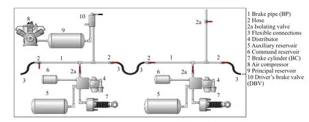
Fig.1 Simplified scheme of air brake system for traction unit (on the left) and wagon/coach (on the right)
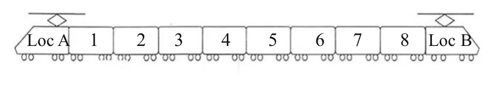
Fig.2 Sketch of ETR500 with eight coaches
In Ref.[2],there is a recent and comprehensive review of the mathematical models used to simulate the air brake systems;most of these models are dedicated to freight trains,for which the modeling of BP venting and filling is more challenging.
The EP or ECP systems have several advantages over classic air brake systems related to safety(lower derailment risk[3–5]),maintenance(lower wheel wear[6]),energy(or fuel) consumption [7,8],network optimization [9,10].They have been tested and used for freight trains in many countries worldwide[11]for at least 20 years,even if they are not the predominant technology for freight trains.Even if there are reports and studies such as Ref.[12],which suggest the application of ECP to freight trains,its application is still controversial because of the higher costs.
Despite this,an extensive European research/industrial program exists to implement EP/ECP systems in freight trains.This program also involves the central coupler,and it is known as digital automatic coupler (DAC) [13,14].The ambitious DAC program aims to vastly improve the railway freight sector in Europe by updating mechanical and pneumatical parts in freight wagons,giving them additional features such as the remote control.
To this end,it is necessary to study the longitudinal train dynamics (LTD) of freight trains in which a part or all wagons are equipped with EP/ECP systems.This paper provides the changes needed to TrainDy software to accomplish this task.
TrainDy is a UIC software [15] designed to model the longitudinal train dynamics of freight trains and can be used,once updated/improved,to better design DAC features.This paper focuses on the modifications needed for the air brake pneumatic model introduced in Ref.[15]to be suitable to simulate the ETR500 and ETR1000 passenger train families: These trains are the high-speed trains operating in Italy.At this aim,Sect.2 reports the main features of these trains,relevant to the topic of this paper.Section 3 reviews the air brake pneumatic model introduced in Ref.[15],pointing out the adaptations needed to simulate ETR500/ETR1000 trains.Sections 4 and 5 report the results of numerical-experimental comparison for different train operations,and with or without the EP brake working.Section 6 presents the paper’s conclusions.
2 Main features of high-speed trains simulated
This section reports the trainsets and some basic data of the ETR500 (in Sect.2.1) and ETR1000 (in Sect.2.2) passenger train families,which are the high-speed trains currently operating in Italy.Some of these data are used to create the pneumatic model of this paper.
2.1 ETR500 train
Although usually classified as an ETR train (electro-train),from a technical point of view,the ETR500 is more like a traditional train: The traction is not distributed along the train (as it is on the ETR 4xy ‘‘Pendolino’’ or the ETR1000).However,it is guaranteed only by the Traction Units placed at the train head/tail.Two E.404 traction units move a variable number of intermediate non-motorized coaches (from 8 to 12 coaches for the configurations used in service) using the Double Symmetric Traction scheme.
Figure 2 shows the composition with eight coaches used in the simulations of this paper.The coach length is 25 m each,the traction unit length is 20.5 m each,and the brake pipe diameter is 31.75 mm,for all vehicles.
From the point of view of the brake system,the pneumatic brake fully meets the traditional UIC requirements,i.e.,the brake system employs air,and it is continuous,automatic,inexhaustible,and gradual.Nevertheless,the coaches are equipped with brake pipe accelerators,and this considerably reduces the in-train forces of this train.
2.2 ETR1000 train
The ETR1000,the newFrecciarossabrand train expanding the AV fleet of Trenitalia,consists of a blocked composition of eight vehicles (divided into two semi-trains independent of each other and symmetrical)with a driver’s cab at each end.The traction is distributed,and the total length is 202 m(see Fig.3).The coach length is 24.9 m each,the length of vehicles with the driver’s cab(DM1 and DM8)is 26.3 m and the brake pipe diameter is 31.75 mm,again for all vehicles.
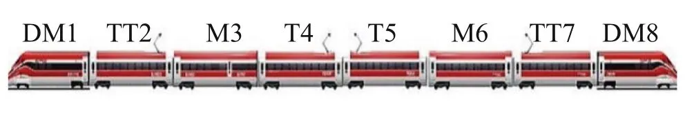
Fig.3 Sketch of ETR1000 with eight vehicles (two semi-trains)
The continuous traction power is equal to 9.8 MW under 25 kV AC 50 Hz catenary;it is provided by four independent converters that power 16 asynchronous threephase traction motors.
The ETR1000 has two different brake systems in parallel: a direct electro-pneumatic brake and an indirect brake.The direct brake is used in service and emergency braking(optional),in the integrated braking mode with the electro-dynamic(ED)brake or rheostat brake.The indirect brake is used for emergency braking and as support service braking in the event of a failure of the direct brake.
3 Pneumatic model
The original pneumatic model is here reported briefly for the sake of clarity.The brake pipe (BP) is modeled by an elongated circular pipe with a variable cross section from which air can be blown or spilt from the ends or along the pipe through the side wall.The BP has a constant diameter within each vehicle and a diameter reduction for the flexible connection between two consecutive vehicles.
From the conservation of mass and energy and the balance of momentum,within the above hypotheses,the governing equations become
where ρ is the density,uis axial velocity,pis pressure,Tis temperature,and all of them are considered as mean values on the general cross sectionSof diameterDand abscissax;qis the specific energy,cvis specific heat at constant volume,andtakes into account the dissipative sources (there,fis the distributed coefficient of pressure loss,Kis concentrated coefficient of pressure loss,and sgn(∙) sign function);φTis the exchanged thermal flux,ris gas constant,andis in-flow or outflow mass flux;and,finally,subscriptlrefers to lateral quantities,which must be computed by imposing the correct boundary conditions.
The driver’s brake valve (DBV),used by the driver to control the train operation,is modeled as a lateral nozzle having three different diameters corresponding to three different braking scenarios,i.e.,service brake,emergency brake and brake release.In particular,the service brake was modeled by considering a nozzle with a fixed diameter having on one side the pressure of BP and on the other side a variable pressure until the maneuver target pressurePtis reached:
This latter pressure decreases following two different gradients depending on the BP pressure: for BP pressure greater than 4.5 bar (pressure relative to air pressure) and lower than 4.5 bar.Therefore,only two gradients were considered,and the transition pressure was fixed.
To properly model the BP venting of ETR1000,considering more transition pressures along with corresponding gradients represents a generalization of the previous simple model,which now considers several transition pressuresPiand for each one a corresponding gradient for pressure reductionGi.This way provides a good agreement between numerical simulations and experimental measurements,as shown in the figures of Sects.4 and 5.
3.1 Electro-pneumatic (EP) brake modeling
To minimize the braking activation delays between consecutive vehicles in a train,the electro-pneumatic (EP)brake system has been introduced in the Railway sector.It is customary for passenger trains,as said in Introduction.This type of braking is also known as electronically controlled pneumatic(ECP)brake.In EP(or ECP)systems,an electric cable is fitted along with the brake pipe.It sends brake and release signals to distributor valves on individual wagons to eliminate the braking delays caused by brake pipe pressure variation.
This system is modeled as a lateral nozzle attached to the brake pipe of each wagon,having a diameter capable of locally discharging the pressure,respecting the UIC Leaflet 541-5[16];this diameter is a function of the time needed to reduce the pressure from 5 to 3.5 bar and of the wagon length.The time to reduce the pressure from 5 to 3.5 bar is a function of the specific EP system.Figure 4 provides a diagram correlating the nozzle diameter to the wagon length and the time to reduce the pressure in the brake pipe from 5 to 3.5 bar.
A trainset made of seven identical wagons(or coaches),each simultaneously discharging the brake pipe with the same nozzle,has been used to plot the diagram in Fig.4.The given nozzle diameter is capable of reducing the air pressure in the BP from 5 to 3.5 bar,at the middle of the fourth wagon,in the time given in the legend.Considering a lower number of wagons in the trainset,e.g.,3 or 5(monitoring the pressure reduction in the second and third wagon of the trainset,respectively),reduces the computational time needed to obtain a similar diagram,providing diameters slightly different (usually higher),as Fig.5 shows.Increasing the number of wagons in the train provides a solution less dependent on un-avoidable numerical approximations;moreover,since these numerical errors depend on the pressure wave reflections,the errors reduce with the increase in wagon length.Figure 5 refers to a time for reducing the pressure in the BP of 3 s;other times provide similar curves.
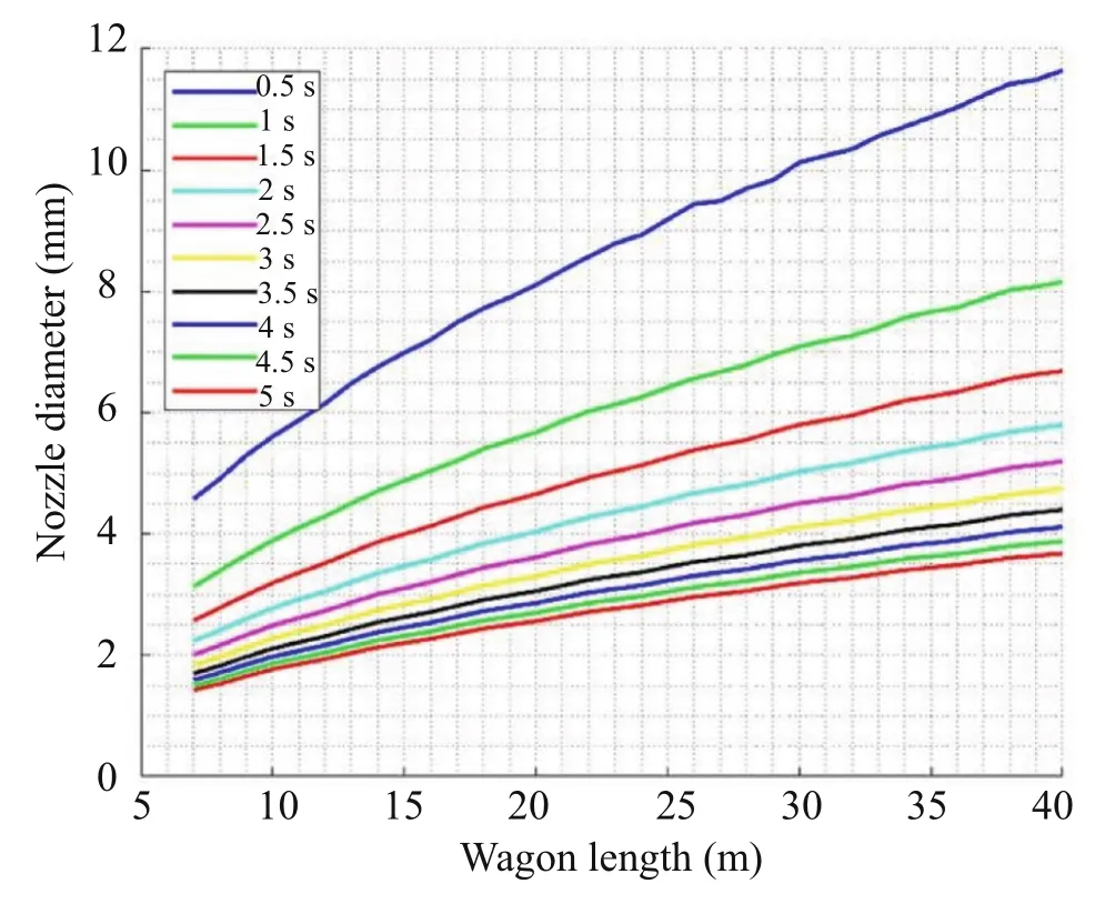
Fig.4 Nozzle diameter as a function of wagon length and time to reduce pressure from 5 bar to 3.5 bar in brake pipe
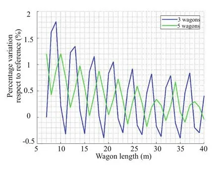
Fig.5 Variation in nozzle diameter with wagon length for different numbers of wagons in the trainset
By using the fitting capabilities of commercial software,such as MATLAB®,it is possible to find a simple analytical model of Eq.(3) to fit the numerical data of Fig.4 and determine the diameter (in mm) of the equivalent nozzleDEP:
wherelis the wagon length,andtis the time to reduce BP pressure from 5 to 3.5 bar locally.The values of R-squared adjusted and root-mean-square error equal to 99% and 0.21,respectively,characterize the fitting.
Once the diameter of the equivalent nozzle,which simulates the valve of the EP brake,is found,and the counter pressure is generalized,the other standard TrainDy models are suitable to simulate the brake pipe venting and brake cylinders filling of the ETR500 and ETR1000 trains.In particular,the brake cylinder filling is still obtained by using the distributor transfer function,and tuning coefficients are employed to approximate the application stroke and in-shot function (the first phase of brake cylinder filling),as described in Ref.[15].
4 Simulation results for ETR500
The first test refers to an emergency braking commanded by the leading traction unit,not considering the EP system.This test has allowed the tuning of the parameters listed in Table 1,where the parameters of the last three rows refer to the TrainDy pneumatic model and are described in Ref.[15].The parameters are listed in the order of tuning:All of them affect the tuning phase,but they can be set in many cases independently since they affect different parts of the curves.For example,the initial pressure in BP shifts all the pressures in BP vertically,whereas the time for emergency braking moves them horizontally.

Table 1 Tuned parameters for ETR500
Even if autonomous identification of the parameters is possible,as done in Ref.[17],manual identification is usually quick,especially for a small number of tests,and matches experimental measurements well.
Figure 6 provides a comparison between the numerical results (solid lines) and experimental measurements (circles).The agreement is like that obtained during the TrainDy validation process [15]: The simplified numerical model of brake cylinder(BC)filling is not able to catch the pressure oscillation in BC of wagon 1,as shown by the figure.Figure 7 is like Fig.6,but the venting of the brake pipe is initiated by the guided(last)traction unit.The set of parameters used is the same for the two tests,except the time to start the emergency braking set equal to 0.41 s.The numerical-experimental agreement is still satisfactory.
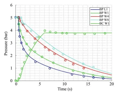
Fig.6 Time evolution of pressure in BP and BC for ETR500.The first traction unit vents the BP.The circles report the experimental data

Fig.7 Time evolution of pressure in BP and BC for ETR500.The last traction unit vents the BP.The circles report the experimental data
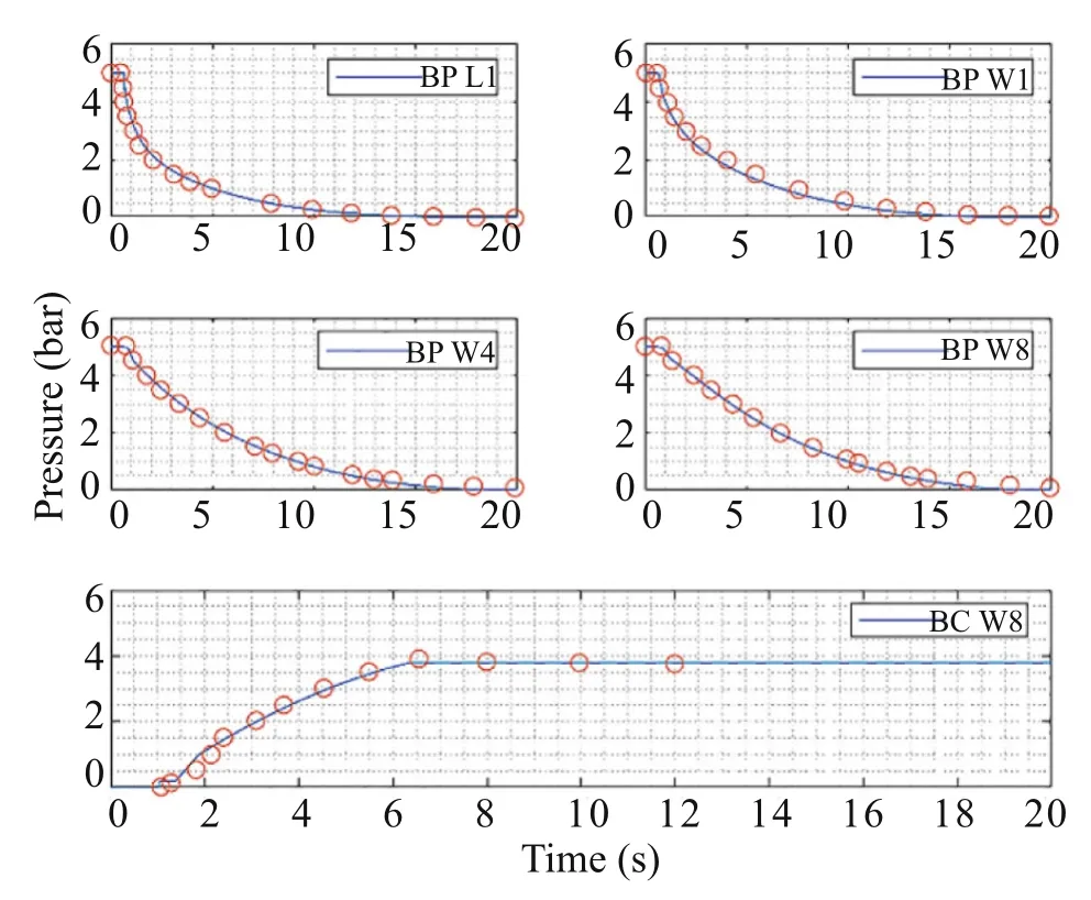
Fig.8 Time evolution of pressure in BP and BC for ETR500.BP is locally vented by the pneumatic brake accelerators,starting from the leading traction unit.The circles report the experimental data
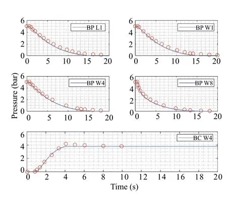
Fig.9 Time evolution of pressure in BP and BC for ETR500.BP is locally vented by the pneumatic brake accelerators,starting from the guided traction unit.The circles report the experimental data
4.1 Pneumatic brake accelerators active
When the pneumatic brake accelerators are active,the venting of the brake pipe occurs at each wagon and starts when an air pressure drop in BP of 0.1 bar is detected.The analysis of the experimental results shows that the pneumatic brake pipe accelerators locally reduce the BP pressure from 5 to 3.5 bar in 4.25 s;the corresponding diameter for the equivalent nozzle is 3 mm.
Figure 8 compares the numerical results (solid lines)and experimental measurements (circles) when the pneumatic brake accelerators are active,and the leading traction unit starts the emergency braking.Figure 9 reports a similar comparison when the emergency braking is started by the last traction unit,using the same data set,except for the starting time of the emergency braking.These figures use the ‘‘subplot’’ feature since the different pressure evolutions in BP were very similar because of the local venting.Also,in this case,the numerical–experimental agreement is satisfactory.
5 Simulation results for ETR1000
The pneumatic system of ETR1000 has been tested considering several classic (i.e.,with EP deactivated) applications of emergency braking from different starting speeds.The first test refers to an emergency braking commanded by the leading traction unit from 120 km/h.Inthis condition,the maximum air pressure at BC of T5 and M6 is equal to around 2.75 and 3.4 bar,respectively.This test resulted in tuning the parameters listed in Table 2.The parameters of the BC are the same as those of the ETR500,except for the times to reach 95 and 100%of the maximum pressure in the BC.Moreover,the coefficient of concentrated pressure loss in hose connections is highly reduced(from 7 to 0.7),to quickly match experimental data.

Table 2 Tuned parameters for ETR1000
This test was modeled as an exceptional service braking:Up to a transition pressure of 0.7 bar,the pressure gradient creates a sonic flow in the equivalent nozzle,as occurs during an emergency braking.Then,up to 0 bar (relative pressure),the pressure gradient is 0.02 bar/s.
Figure 10 compares the numerical results (solid lines)and experimental measurements(circles)again with a good matching.Figure 11 is like Fig.10,but the emergency braking starts when the train speed is 140 km/h.The set of parameters used is the same for the two tests,except for the time to start the emergency braking,which equals 1.31 s.The numerical-experimental agreement is still satisfactory.
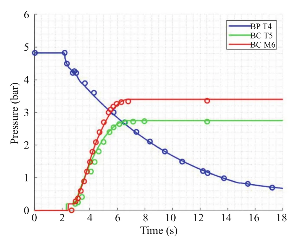
Fig.10 Time evolution of pressure in BP and BC for ETR1000.The first traction unit vents the BP;the speed is 120 km/h.The circles report the experimental data
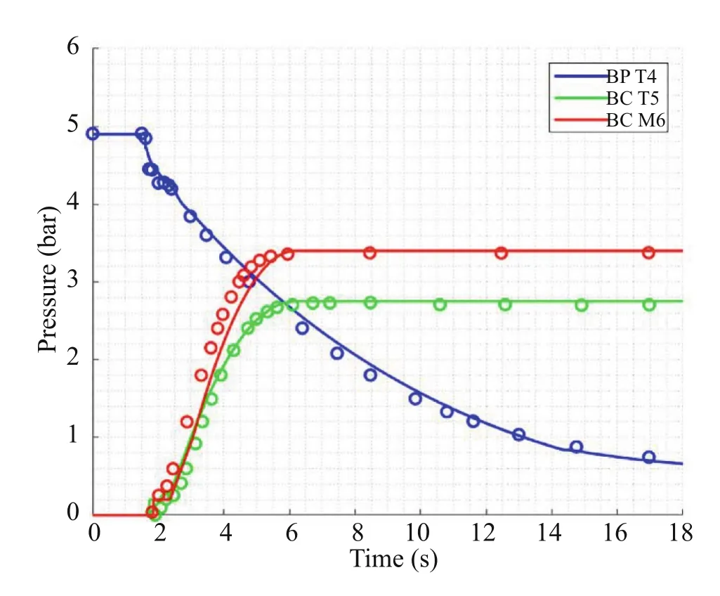
Fig.11 Time evolution of pressure in BP and BC for ETR1000.BP vented by leading traction unit from 140 km/h.The circles report the experimental data
5.1 EP system active
When the EP system is active,the venting of the BP occurs at each vehicle and starts simultaneously for each vehicle since it is electronically controlled-activated.In order to match numerical simulations and experimental measurements well,emergency braking was simulated in TrainDy as an exceptional service braking,as before;moreover,the counterpressure reduction has been modeled as in Table 3.
By analyzing the experimental measurements,it is found that the EP system locally reduces the BP pressure from 5 to 3.5 bar in 0.85 s;the corresponding diameter for the equivalent nozzle is 8 mm for the coaches.
Figure 12 compares the numerical results and experimental measurements when the EP system is active.Again,the numerical-experimental agreement is satisfactory.However,the time to reach 95 and 100% of the maximum air pressure in BC is set to 2.9 s and 3.2 s,respectively.
6 Conclusions
The paper shows the modifications and the improvements needed to the pneumatic model of TrainDy to simulate modern passenger trains equipped with EP (or ECP) brake systems.It also shows the sound matching between the numerical results and the experimental measurements for different trainsets (ETR500 and ETR1000) and brake system conditions(EP active or not).In this way,it is possible to simulate the longitudinal train dynamics of passenger trains when they are coupled to a classic train (e.g.,for train recovery) or when it is needed to study a malfunctioning brake system.However,the generalization of the TrainDy model is not yet complete and requires,in future work,the possibility of modifying the pressure of the brake cylinders according to the speed of the train (to avoid possible adhesion problems) and the customization of the running resistance,which is relevant when the initial speed of the train is above 100 km/h.Nevertheless,the model can simulate trains like those explicitly considered here(ETR500 and ETR1000) but having a different number of coaches or coaches with different length.In general,it can simulate the braking operation of trains with EP brake system.If the EP brake system is different,the tuning parameters of the model in terms of transition pressure and corresponding gradients should be adjusted.This is compliant with the general pneumatic model of TrainDy and has proved to be effective.
Open AccessThis article is licensed under a Creative Commons Attribution 4.0 International License,which permits use,sharing,adaptation,distribution and reproduction in any medium or format,as long as you give appropriate credit to the original author(s) and the source,provide a link to the Creative Commons licence,and indicate if changes were made.The images or other third party material in this article are included in the article’s Creative Commons licence,unless indicated otherwise in a credit line to the material.If material is not included in the article’s Creative Commons licence and your intended use is not permitted by statutory regulation or exceeds the permitted use,you will need to obtain permission directly from the copyright holder.To view a copy of this licence,visit http://creativecommons.org/licenses/by/4.0/.
杂志排行

Railway Engineering Science的其它文章
- The effect of controllable train-tail devices on the longitudinal impulse of the combined trains under initial braking
- A numerical method for the simulation of freight train emergency braking operations based on the UIC braked weight percentage
- Influence of quick release valve on braking performance and coupler force of heavy haul train
- Braking distance prediction for vehicle consist in low-speed on-sight operation: a Monte Carlo approach
- An approach for simulating the air brake system of long freight trains based on fluid dynamics
- HIL testing of wheel slide protection systems: criteria for continuous updating and validation