Ballistic impact response of flexible and rigid UHMWPE textile composites: Experiments and simulations
2023-05-06HongxuWangDakshithaWeerasinghePaulHazellDamithMohottiEvgenyMorozovJuanEscobedoDiaz
Hongxu Wang,Dakshitha Weerasinghe,Paul J.Hazell,Damith Mohotti,Evgeny V.Morozov,Juan P.Escobedo-Diaz
School of Engineering and Information Technology,The University of New South Wales,Canberra,ACT,2600,Australia
Keywords:Impact behaviour Textile composite UHMWPE fibre Energy absorption Finite element analysis
ABSTRACT This study elaborates on the effects of matrix rigidity on the high-velocity impact behaviour of UHMWPE textile composites using experimental and numerical methods.Textile composite samples were manufactured of a plain-weave fabric (comprising Spectra® 1000 fibres) and four different matrix materials.High-velocity impact tests were conducted by launching a spherical steel projectile to strike on the prepared samples via a gas gun.The experimental results showed that the textile composites gradually changed from a membrane stretching mode to a plate bending mode as the matrix rigidity and thickness increased.The composites deformed in the membrane stretching mode had higher impact resistance and energy absorption capacity,and it was found that the average energy absorption per ply was much higher in this mode,although the number of broken yarns was smaller in the perforated samples.Moreover,the flexible matrix composites always had higher perforation resistance but larger deformation than the rigid matrix counterparts in the tested thickness and velocity range.A novel numerical modelling approach with enhanced computational efficiency was proposed to simulate textile composites in mesoscale resolution.The simulation results revealed that stress and strain development in the more rigid matrix composite was localised in the vicinity of the impact location,leading to larger local deformation and inferior perforation resistance.
1.Introduction
Woven fabrics and textile composites made of highperformance polymer fibres are ideal materials for protective structures,such as body armour,ballistic helmets,and engine containment systems,against high-velocity impacts.The commonly used fibres for impact-resistant applications are aramid fibres(e.g.,Kevlar®and Twaron®)and ultra-high molecular weight polyethylene(UHMWPE)fibres(e.g.,Spectra®and Dyneema®)[1].In textile composites,these fibres,being in the form of textile fabrics(woven,knitted,or braided)as the reinforcement phase,are embedded in a matrix with distinct interfaces between them.Generally,fibre reinforcements are much stronger and stiffer than the matrix and,therefore,dominate the properties of the composite.On the other hand,the matrix material encompassing the fibre reinforcement serves the purpose of load transfer among fibres,protecting fibres from environmental damage,and holding fibres in place in their designated position and orientation [2].
The load-bearing characteristics of a composite are primarily facilitated by fibre reinforcement,which also occupies a higher volume fraction.Therefore,the effects of reinforcement parameters on the impact behaviour of composite materials have been extensively investigated[3—15].In particular,it has been confirmed that ply orientation greatly affects the ballistic limit and back face deformation of UHMWPE laminates with unidirectional fibre plies,and the cross-ply (0°/90°) lay-up possesses the best penetration resistance [3,4].However,ply orientation is less influential on the impact behaviour of textile composites reinforced by woven fabrics[5,6].It has also been found that weave structure plays an important role in controlling the impact performance of textile composites [6—9].Other studied factors include reinforcement continuity [10],laminate thickness [6,11—13],fibre hybridisation[14,15],etc.
The effects of matrix properties on the impact behaviour of composite materials have been given far less attention compared to fibre reinforcements [16].This is especially true for textile composites with woven fabric reinforcements,where understanding of how matrix properties influence their impact behaviour is still in the infant stage.Early studies by Lee et al.[17,18]showed that Spectra® fabric-reinforced laminates with a stiff vinyl ester resin had a higher ballistic limit and longer impact fatigue life than the flexible polyurethane resin counterpart.It was concluded that yarn mobility was constrained more by the stiff matrix than the flexible matrix,which led to the engagement of a higher number of yarns by the projectile,thereby forcing more yarns to fail and providing better impact performance.In somewhat contradiction to the findings by Lee et al.,Wang et al.[19]revealed that Dyneema®textile composites with flexible matrices performed better in terms of perforation resistance and energy absorption than their counterparts with rigid matrices.The composite’s transverse deformation was constrained by the rigid matrix to an area relatively smaller than the flexible matrix,leading to larger localised strain developed and lower perforation resistance.A later investigation by Khodadadi et al.[20]supported this argument that a rigid matrix had a negative effect on the impact performance by comparing Kevlar® textile composites with rigid epoxy matrix and flexible rubber matrix,respectively,under high-velocity impact loading.Later on,Mahesh et al.[21]found that complaint hybrid composites reinforced by jute fabrics exhibited the best impact resistance and energy absorption capability,followed by stiff epoxy composites,compliant rubber composites,and neat jute fabrics in sequence.Hence,it appears that there remains a lack of persuasive reasons for the contradictory findings in the literature,which requires further studies to better understand the effects of matrix properties on the impact behaviour of textile composites.
Numerical modelling has been proven as a powerful tool for analysing the responses of materials and structures to dynamic loads,e.g.,impact and blast.A major advantage of numerical modelling is its ability to produce highly informative results,such as stress distribution,wave propagation,contact force,failure mode,etc.It is therefore a useful approach to elucidate the underlying mechanisms of fabric-based materials during the impact process [22],which would be impossible to determine through empirical methods.Numerical modelling of dry woven fabrics with various methods has seen consistent progress over the past two decades,and mesoscale approaches with individual yarns explicitly modelled using solid elements are state of the art [23].However,there is a paucity of research on mesoscale modelling of textile composites under impact loading,due to their complex and hierarchical microstructures.Gopinath et al.[24]developed a simplified finite element (FE) model,which assumed yarns had a rectangular cross-section and a polyline path,to simulate the impact behaviour of textile composites with plain-weave Kevlar®fabrics.Their results showed that the textile composites containing a flexible matrix absorbed higher energy than composites containing a stiff matrix.However,this was only true for composite thicknesses ranging from 1 mm to 5.4 mm (1—5 layers).The opposite was true when the thickness was increased to 7.6 mm (7 layers).Khodadadi et al.[25]adopted a similar modelling approach by considering yarn cross-section as a rectangle and yarn path as a segmented line to simulate the impact behaviour of Kevlar®textile composites with high-hardness and low-hardness rubber matrices,respectively.These simplified FE models,however,are deficient in several important respects,such as unrealistic yarn crimp and bending stiffness,which would cause errors in the impact response.Even though trends in the literature clearly show that a better approximation of the yarn geometry allows a more realistic simulation of fabric-based materials,mesoscale numerical modelling of textile composite materials at better resolution for impact-related scenarios is yet to be explored.
Therefore,given the current uncertainty about the role of matrix rigidity in governing the dynamic behaviour of textile composites under high-velocity impact loading,this study aims to offer better insights into this issue by comparing the impact performance of textile composites with different matrices via both experimental and numerical approaches.A plain-weave fabric consisting of Spectra®1000 fibres and selected four different resins were used to manufacture textile composite specimens with different thicknesses.High-velocity impact tests were carried out to evaluate the effects of matrix properties on the energy absorption,penetration resistance,deformation resistance,and damage extent of composite specimens.Furthermore,a novel mesoscale FE model was developed to figure out how matrix rigidity affects the deformation and failure mechanisms of textile composites during the impact process.
2.Materials used and specimen preparation
2.1.Fabric reinforcement and resin matrices
The plain-weave fabric made of Spectra® 1000 fibres provided by JPS Composite Materials was used for making textile composite specimens.Both the warp and weft yarns contain 120 fibres and have a linear density of 650 denier(the mass in grams per 9000 m),and the bulk density of the fibre material is 0.97 g/cm3.The areal density of a single layer of fabric is 0.0095 g/cm2.Fig.1 shows the woven fabric construction,yarn paths and cross-sections.
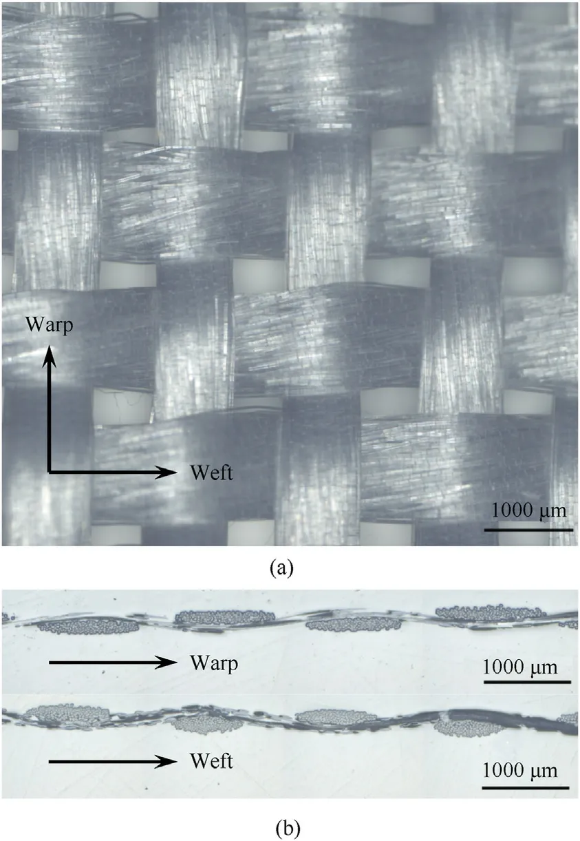
Fig.1.Optical microscopy images showing: (a) The plain-weave pattern of the Spectra® fabric,and (b) the paths and cross-sections of warp and weft yarns.
The composite specimens were fabricated using four resin matrices with different material properties.Table 1 lists the constituents of resin products and their cured mechanical properties from the manufacturers.Firstly,a West System® 105 epoxy resin with 206 slow hardener was chosen as a matrix material owing to its high modulus and strength after cure.However,because this epoxy resin is relatively brittle,the second type of matrix was manufactured using the West System® 105 epoxy resin and Nanostrength® M52N,an acrylate triblock copolymer that selfassembles in the nanometre scale.This triblock copolymer was applied as the toughening modifier for the epoxy resin,and it had been shown that the addition of this triblock copolymer to the epoxy resin significantly improved the impact performance of Kevlar® fabric-reinforced laminates [26]and glass fabricreinforced laminates [27].The triblock copolymer was added to the epoxy resin with a weight ratio of 1:10 using a magnetic stirrer which thoroughly mixed the components at 90°C for 2 h at a speed of 290 rpm.The designated hardener quantity was added to the mixed solution just before making the specimens.The third resin was Epopol® 7320,supplied by Vee-Tek Australia,and is a urethane-modified epoxy resin having a low modulus and strength but very high elongation.Finally,the fourth resin was Eracast XPE15-1957 which is a flexible and tough polyether-based polyurethane resin supplied by Era Polymers.The wet lay-up method was used to manufacture all the composite samples since the resins possessed low viscosities and long gel times.These four resin matrices are denoted hereafter by “Epoxy”,“Nano”,“Epopol”,and“PU”,respectively.
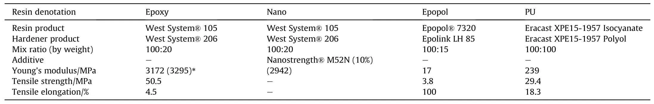
Table 1 Summary of resin matrices used.
2.2.Composite manufacturing
The traditional wet lay-up method used to manufacture the composites is described as follows.The Spectra®fabric was cut into layers of desired dimensions (600 × 400 mm2) firstly.Subsequently,the fabric plies were impregnated using the resins prepared as described in Section 2.1.The resin-impregnated plies were then stacked manually layer by layer.Composite samples containing 4,8,and 16 plies were manufactured using the four different resins.The fabric plies were laid up such that their orientations were aligned.The resin-impregnated laid-up plies containing different ply numbers were positioned inside a vacuum bag where a pressure of 90 kPa was applied for curing at room temperature.Finally,the laminates were segmented into rectangular specimens with a dimension of 250×150 mm2,after fully curing.In addition,neat fabric specimens with the same size and number of plies were prepared to examine the role of resin addition in altering the impact behaviour.
The average values of measured reinforcement fraction,areal density,and thickness of all the composite samples are given in Table 2.Because the density and viscosity are different among the used resins,there were slight differences in these values of composites.Each sample is assigned a denotation to be referenced for discussing the test results,as shown in Table 2.For example,the composite sample made of 16 layers of Spectra®fabric and PU resin is designated as “16S/PU”.Similarly,the neat fabric specimens consisting of 4,8,and 16 plies are represented by “4S”,“8S”,and“16S”,respectively.
3.Experimental methodology
The impact tests were conducted using a single-stage gas gun[28],and the details of the experimental setup are shown in Fig.2.A steel sphere with a diameter of 12 mm and a mass of 7.05 g was propelled to predetermined velocities to impact the target centre at normal incidence.The impact velocity of the projectile was controlled by the charged pressure in the gas tank and measured using two pairs of photoelectric sensors.The impact tests were conducted at three nominal impact velocities of 113 ± 7,152 ± 3,and 196±2 m/s(i.e.,nominal impact energies of 45±5,82±3,and 135±3 J).Under each impact loading condition,only one specimen of each type of composite was tested,which was conventional in high-velocity impact testing.
The specimens were secured into a target holder by clamping at the top and bottom sides over a width of 50 mm,which left a square part of 150×150 mm2in the middle.The target holder was situated in a chamber,as shown in Fig.2(b).During the impact process,the chamber was fully sealed,only leaving a small hole on the front side to allow the projectile to pass through,so as to protect thesurrounding equipment.There were transparent Perspex windows on the left and right sides of the chamber,so the target’s transient impact response was captured by a high-speed video camera(Phantom v710) at 18,000 frames-per-second with an exposure time of 10 μs.A plasma light was employed for back illumination.The projectile’s residual velocities during all the tests were determined using the calibrated high-speed videos.The measured impact velocity and residual velocity for each test are summarised in Table A1 in the Appendix.For projectile impacts that perforated the targets,the kinetic energy loss of the projectile was assumed to be equal to the energy absorbed by the target (Et),which can be calculated by Eq.(1).
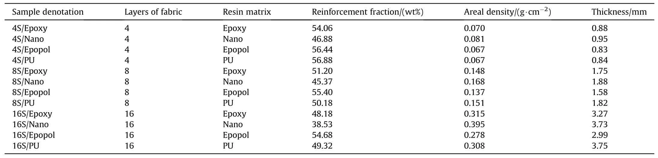
Table 2 Specifications of UHMWPE composite samples.
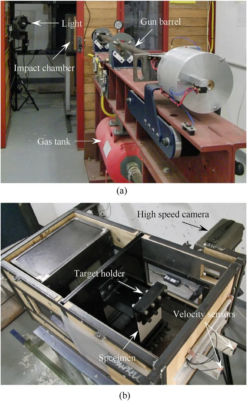
Fig.2.Experiment setup of high-velocity impact tests.
wheremprefers to the projectile mass,virefers to the initial velocity of the projectile,and vrrefers to the residual projectile velocity.
For non-perforating projectile impact,it was assumed that the total projectile kinetic energy was absorbed by the target.In this scenario,Etwas calculated using Eq.(2).
where the composite specimen was not perforated,its maximum dynamic deformation was measured by tracking the movement of the back face centre in the calibrated high-speed video.Additionally,after the impact tests,the composite specimens were examined by backlighting,where damage pattern and damage extent were determined using light-transmission photographs [19].
4.Finite element modelling
A novel approach was proposed in the present work to simulate the impact behaviour of textile composites.A mesoscale FE model was developed with a good balance between computational efficiency and accuracy compared to the present state-of-the-art methods.The FE mesh generation,section definitions,contact interactions and other details of the numerical modelling are discussed in the following sections.
4.1.Element types and fabric mesh generation
Shell elements with variable thicknesses were used to develop the FE mesh of the fabric reinforcement with a mesoscale resolution,whereas hexahedral solid elements were used to model the matrix material.Firstly,a mesoscale fabric mesh was generated with hexahedral solid elements,according to the geometric parameters of the used woven fabric from microscopic measurement,as shown in Fig.1.The detailed method of generating such a mesh is discussed in the authors’ previous work [29,30].Subsequently,four-noded shell elements were generated along the mid-planes of hexahedral solid elements,as shown in Fig.3(a) and Fig.3(b).TheElement Generationtool (Shell by Solid/TShell Midplane) in LSPrePost was used for shell element generation from the solid elements.
Warp and weft yarns were assigned three parts each,as shown in Fig.3(c),which facilitated the assignment of different nodal thicknesses at the shell element nodes.Different nodal thicknesses assigned are graphically illustrated in Fig.3(d).The definitions of node locations and nodal thickness at different node locations of Part 1 and Part 4 (shown in Fig.3(c)) are shown in Fig.4.
Fully integrated shell elements (ELFORM 16) were used with eight integration points through the thickness in order to avoid excessive hourglassing effect usually observed in solid elements[22].Section definitions and nodal thicknesses of different parts are summarised in Table 3.The advantages of using shell elements over solid elements will be discussed in detail in Subsection 5.5.1.
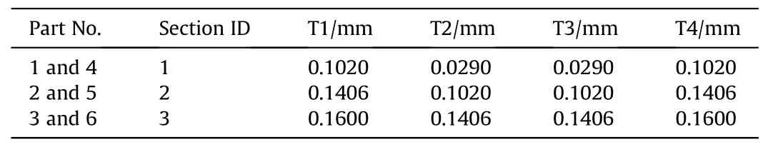
Table 3 Different nodal thicknesses assigned to different Sections and Parts.
4.2.Matrix mesh generation
The matrix material was modelled using a mesh of fully hexagonal solid elements in contrast to the conventionally used meshing method with tetrahedral elements (Fig.5(a)).The shell element fabric mesh is embedded in the fully hexahedral solid element matrix,as shown in Fig.5(b).Three elements were used through the thickness of the composite matrix in order to capture the bending behaviour accurately.The default reduced integrated solid elements (ELFORM 1) were used with a single integration point in order to minimise computational time,but also to avoid shear locking in fully-integrated solid elements.
4.3.Boundary conditions and contact interactions
The top and bottom (horizontal) edges of the composite mesh were fixed by constraining all the translational and rotational degrees of freedom (DOFs) of their nodes,which simulated the fully clamped boundary condition in the impact tests.The DOFs of the nodes at the two vertical edges were unconstrained to replicate the free boundary condition.The projectile was assigned initial velocities along theZ-axis.Only one quarter of the problem was modelled,considering symmetry.Therefore,a symmetric boundary condition was imposed on the nodes lying on the planes of symmetry(XOZ-plane andYOZ-plane,whereOrefers to the origin of theXYZspace) of the composite panel and projectile.
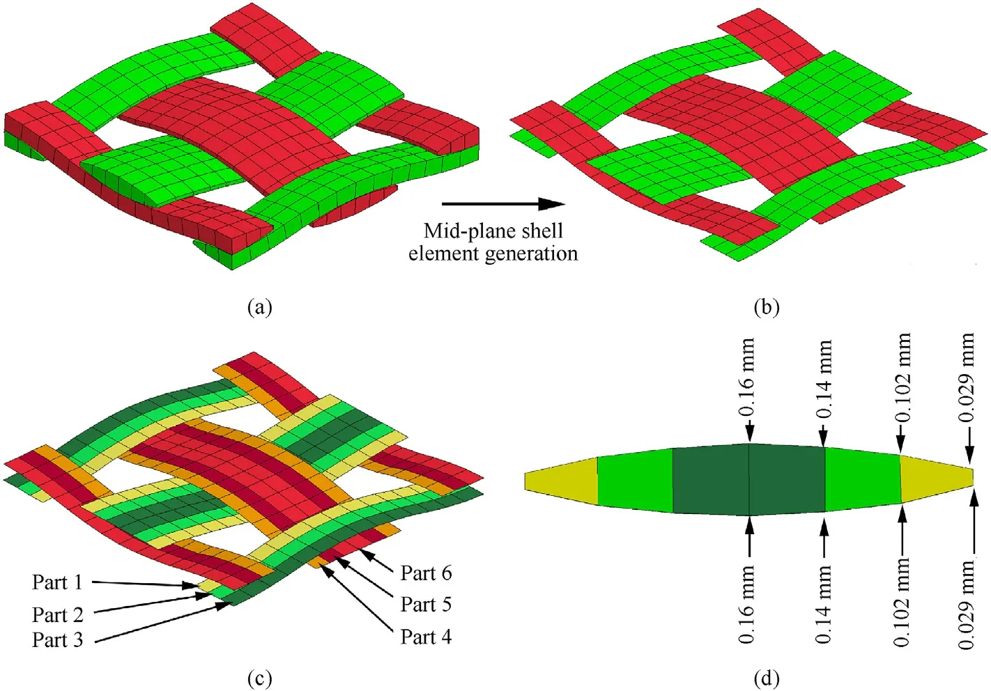
Fig.3.(a)Hexahedral solid element mesh of the fabric repeating unit;(b)Shell elements generated along the mid-planes of solid elements;(c)Different part definitions of the shell elements;(d) Thickness definitions of shell elements at different nodes.
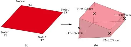
Fig.4.Example of (a) node locations and (b) nodal thickness definitions of shell elements for the parts on yarn edges.
Contact interactions among the yarn parts were defined using the *ERODING_SINGLE_SURFACE contact algorithm,while the matrix-yarn contact was defined using the*CONSTRAINED_SHELL_IN_SOLID keyword.This keyword constraints the shell structures(defined as the shell element part/part setSHSID) to move with the solid elements (defined as the solid element part/part setSSID) and constraints both acceleration and velocity[32].
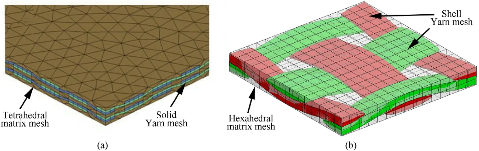
Fig.5.(a) A composite mesh consisting of tetrahedral solid element matrix mesh and hexahedral yarn mesh [31]and (b) the 4-noded shell fabric mesh embedded in hexahedral solid element matrix mesh in the present work.
4.4.Material definitions
The neat fabric with four plies(4S),Epoxy composite(4S/Epoxy)and PU composite(4S/PU)were modelled in the present work.Both Epoxy and PU resins were modelled as elasto-plastic materials using LS-DYNA *MAT_24 (PIECEWISE_LINEAR_PLASTICITY).True stress-strain curves of epoxy [33]and polyurethane[34]materials(see Fig.6) were input as load curves in the material cards,which captured the mechanical behaviour of the matrix materials in the numerical models.Yarn shell elements were set to be eroded when the principal stress reached a value of 3.16 GPa and a strain of 3.5%[35].Similarly,the matrix solid elements were eroded when the principal stress reached 180.3 MPa and principal strain reached 30.9%for epoxy[33],and the principal stress reached 20.9 MPa and principal strain reached 115.3%for polyurethane[34].The material properties obtained at high strain rates [33,34]were used in the numerical models rather than the quasi-static properties described in Table 1,since both epoxy and polyurethane resins exhibit strainrate sensitivity.The primary purpose of numerical modelling here is to elucidate how matrix rigidity controls the deformation and failure mechanisms of textile composites,instead of comparing with the experimental results.
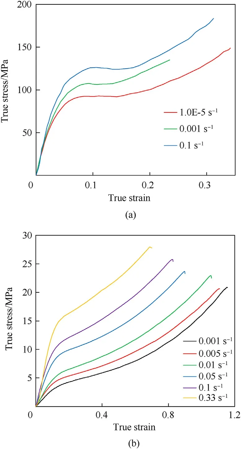
Fig.6.True stress-strain curves of (a) epoxy and (b) polyurethane resins measured under various strain rates [33,34].
5.Results and discussion
5.1.Energy absorption and perforation status
Fig.7 plots the energy absorption of all the impact tests as a function of impact energy.Each discrete data point corresponds to the result of each individual impact test.The actual impact energies varied slightly among the tests at the same nominal breech pressure.The measured impact velocity and residual velocity for each test are given in the Appendix.The 45-degree dashed line in Fig.7 represents all non-perforating(impact energy is equal to absorbed energy) cases.Therefore,while all the non-perforating tests lie on this line,the perforating tests (impact energy >absorbed energy)lie below it.Generally,the perforation resistance of the neat fabric and composite panels increased when the areal density or the number of plies increased.It must be mentioned here that an exception was the composites with Nano matrix: the 8S/Nano laminate (the data point is on the non-perforated line) survived after the impact with an energy level of 135±3 J;however,the 16S/Nano laminate was perforated at this energy level.The reason for this unexpected finding was due to the change of penetration mechanism as the thickness increased.This will be discussed in the following sections.
Fig.8 shows the energy absorption of the 4-ply composite samples subjected to different impact energies.The nominal impact energy levels of 45 ± 5,82 ± 3,and 135 ± 3 J are used to discuss the results in groups.It can be seen that the energy absorption dropped sharply when the rigid matrix composites 4S/Epoxy and 4S/Nano were perforated.The energy absorption continued to increase when the flexible matrix composite 4S/Epopol was perforated.The 4S/PU composite was the only nonperforated sample when subjected to the nominal impact level of 135 ± 3 J,which indicates that the flexible PU resin provided the textile composites with the best penetration resistance among all the used resin matrices.
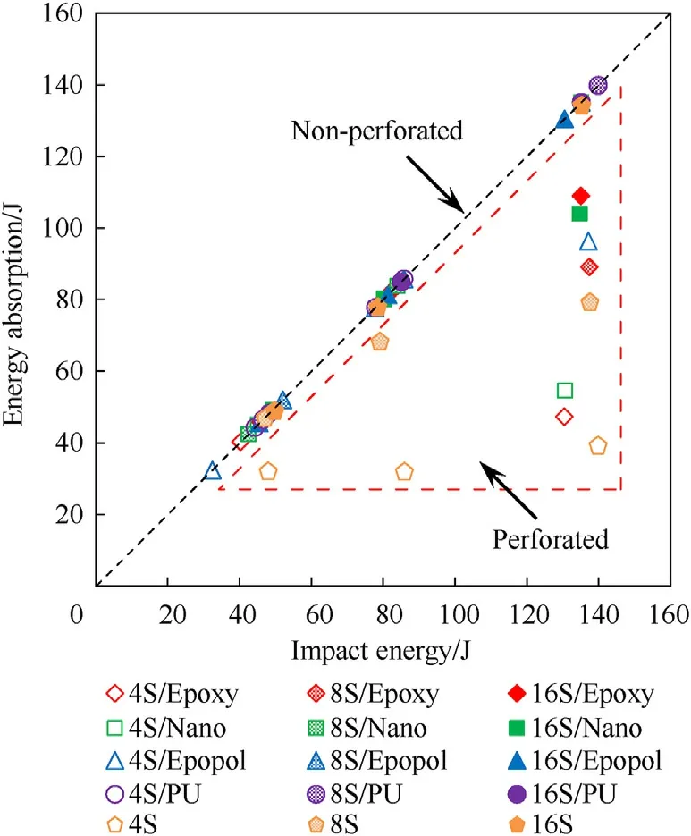
Fig.7.Energy absorption and perforation status of all the tests.
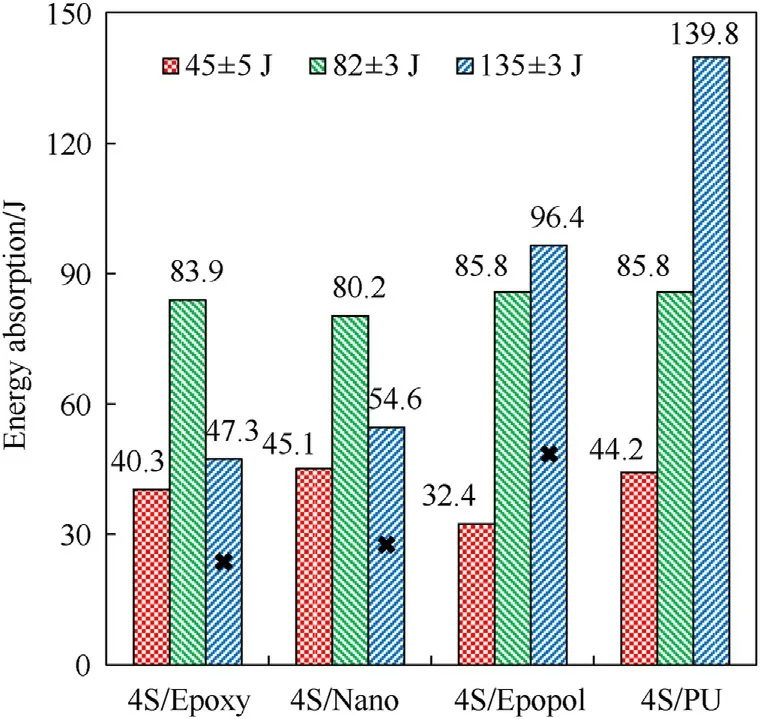
Fig.8.Energy absorption of the 4-ply composites subjected to different impact energy levels (the cross mark “ × ” indicates the perforated cases).
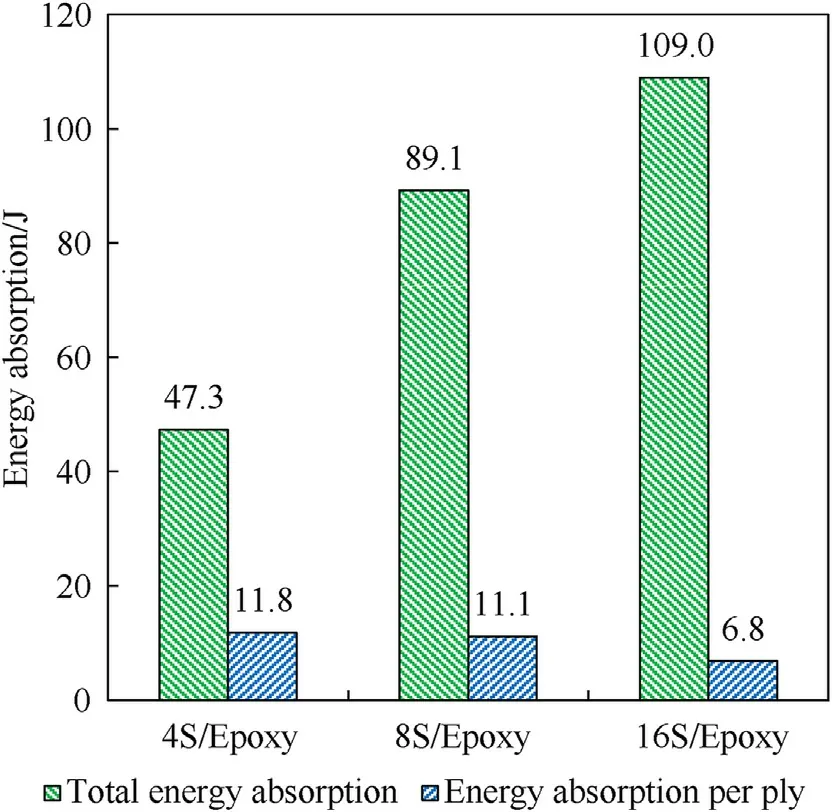
Fig.9.Comparison of the total energy absorption and energy absorption per ply among the Epoxy composites with different numbers of plies subjected to the nominal impact energy level of 135 ± 3 J.
It is,perhaps,not surprising that the energy absorption of some composites increased with thickness,such as the Epoxy matrix composites,as shown in Fig.9.All these composite samples were perforated at the nominal impact energy level of 135 ± 3 J.However,the energy absorption averaged by the number of plies presents an opposite tendency.The energy absorption per ply decreased slightly from 4S/Epoxy to 8S/Epoxy,and it dropped dramatically when the thickness increased to 16 plies.This sudden drop in the energy absorption per ply of the 16S/Epoxy sample was due to the change of penetration mechanism as the thickness increased,which will be explained later.The thinner composites appeared to work more efficiently for impact protection by absorbing more energy per ply.Consequently,it can be speculated that a target constructed by several spaced thin laminates may outperform a single laminate having the same total number of plies for energy absorption in the studied impact velocity range of this work.
The test results showed that the addition of nanoreinforcements in the epoxy resin enhanced the penetration resistance of laminates because 8S/Epoxy was perforated (below the non-perforated line in Fig.7)at the nominal impact energy level of 135 ± 3 J while 8S/Nano survived (on the non-perforated line).This is in keeping with previous studies on Kevlar® fabricreinforced laminates [26]and glass fabric-reinforced laminates[27].When taking areal density into consideration,the laminates made of the Nano matrix did not have an advantage over those made of the pure Epoxy matrix.As shown in Fig.10,the specific energy absorption values standardised by the areal density were almost the same for the 4S/Epoxy and 4S/Nano composites at the nominal impact energy level of 135 ± 3 J.Further,when the thickness increased to 16 plies,the specific energy absorption of 16S/Nano was lower than that of 16S/Epoxy.
5.2.Penetration mechanism
During the penetration process,all the tested fabric samples resembled a membrane response.For instance,Fig.11(a) demonstrates the impact process of the 4S fabric panel subjected to the nominal impact energy level of 45±5 J.The transverse wave,which deflects the fabric material in the projectile’s impact direction,was found to emanate from the impact location and travel towards the panel edges.The stretching and decrimping of the yarns decreased the weave tightness and thereby increased the yarn mobility in the vicinity of the projectile.So when the fabric was deformed to an extent,it was found that most of the yarns slid off from the projectile and were pushed aside without being broken to allow the passage of the projectile.Several horizontal yarns were pulled out from the fabric because of the unconstrained boundary condition on the left and right sides,as shown at the 611 μs frame.When yarn slippage occurred in the fabric panels,the slipped yarns did not absorb as much energy as the yarns stretched to failure in the composites[30,36].
The 4-ply composites,irrespective of resin matrix,also acted in a membrane dominant mode,sustaining the transverse impact loading with in-plane tensile stresses,which was qualitatively similar to the impact response of neat fabric panels.Taking the 4S/Nano composite for example,as shown in Fig.11(b),it underwent large deflection and a bulge was formed,which produced high tensile stresses in the material as the composite was stretched.One function of the matrix is to constrain the yarn movement,so the yarn slippage could not occur in the textile composites.As a result,the yarns were able to absorb more energy before failure,and the projectile was stopped by the composite and bounced back at this impact energy level,as shown at the 1167 μs frame.When the impact energy increased,the yarns in direct contact with the projectile failed by the high tensile stress and let the projectile pass through.
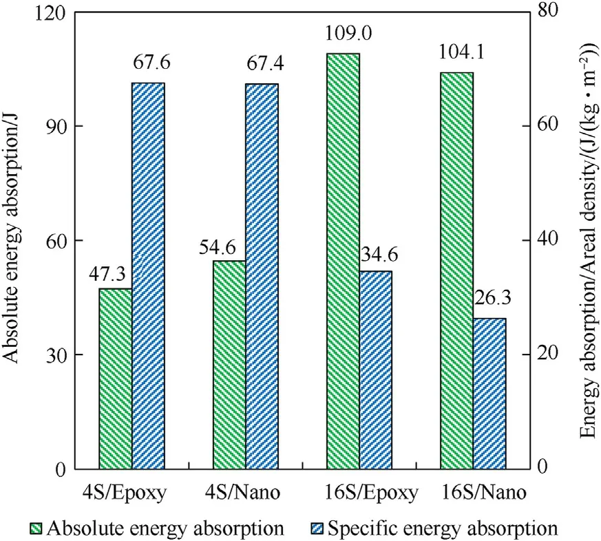
Fig.10.Comparison of the absolute energy absorption and specific energy absorption standardised by areal density between the composites made of Epoxy and Nano matrices subjected to the nominal impact energy level of 135 ± 3 J.
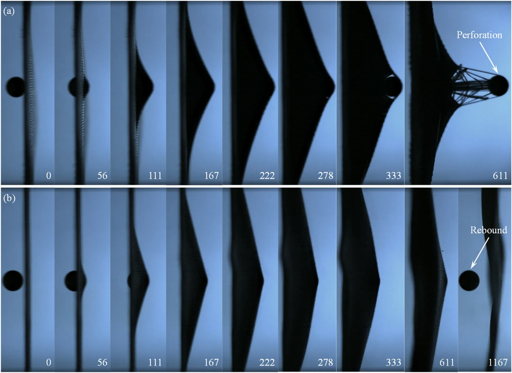
Fig.11.Selected high-speed video frames showing the impact processes of(a)4S fabric and(b)4S/Nano composite subjected to the nominal impact energy level of 45±5 J(time unit: μs).
As shown in Fig.12(a),the bulging in the thicker 16S/Epoxy composite became less pronounced and was perforated at an early stage when subjected to the nominal impact energy of 135±3 J.In contrast,the 16S/PU composite still exhibited a membrane stretching mode similar to the thinner laminates,as shown in Fig.12(b).In fact,the impact response of 16-ply composites with rigid Epoxy and Nano matrices was dominated by the plate bending mode where the impact loading was resisted by bending and shear stresses,which will be proved from the back face deformation history and damage pattern later.Therefore,the matrix rigidity had a strong influence on the impact behaviour of textile composites.The composites with a flexible matrix had a better penetration resistance.
5.3.Back face deformation
In addition to perforation resistance and energy absorption,back face deformation is an important consideration in the engineering design of body armour.Thus,the dynamic out-of-plane deformation of each composite specimen was measured by tracking the movement of its back face centre (i.e.,the impact location)using Tracker,a free video analysis and modelling tool.A high-speed video was imported into Tracker and then calibrated by a known length(the projectile’s diameter was known as 12 mm)to set the ratio of the actual distance in millimetres (or any desired length unit) to the image distance in pixels between two points.After that,a tiny area around at back face centre was selected to create a template image of a feature of interest in the first video frame.Subsequently,the movement of the back face centre was tracked automatically by searching each following frame for the best match to that template.The template image evolved to adapt to shape and colour changes over time.
Fig.13 summarises the back face deformation histories for all the composite samples subjected to the nominal impact energy of 45 ± 5 J.Interestingly,the 4-ply laminates,irrespective of the matrix,had very close deformation history curves.As the laminate thickness increased,the peak deformations decreased for all the samples,and the history curves started to diverge and form into two groups,the laminates made of rigid resins and flexible resins.The 8S/Epopol and 8S/PU composites had higher peak deformation values than 8S/Epoxy and 8S/Nano.When the laminate thickness increased further,16S/Epopol and 16S/PU still showed similar deformation responses to the thinner laminates,only with lower peak values.However,the 16S/Epoxy and 16S/Nano composites exhibited a distinct response,which suggests that they had changed from a membrane dominant mode to a plate dominant mode as the thickness increased to 16 plies.
The results discussed so far indicate that the membrane stretching mode is preferable for energy absorption and penetration resistance of textile composites in the studied velocity range,since this mode allows the material to absorb energy and fail in tension,which is the most efficient way to utilise fibres with high tensile strength and toughness.When the matrix rigidity and the thickness increased,the textile composite was gradually dominated by the plate bending mode,which caused the energy absorption efficiency and penetration resistance to drop sharply.The finding here is in agreement with the results of Gopinath et al.’s work[24],where the aramid fabric-reinforced laminates with a flexible matrix were found to have higher energy absorption and penetration resistance than those with a rigid matrix when the thickness ranged from 1 mm to 5.4 mm.
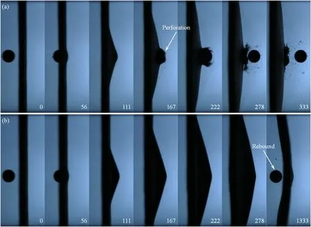
Fig.12.Selected high-speed video frames showing the impact processes of(a)16S/Epoxy and(b)16S/PU composites subjected to the nominal impact energy level of 135±3 J(time unit: μs).
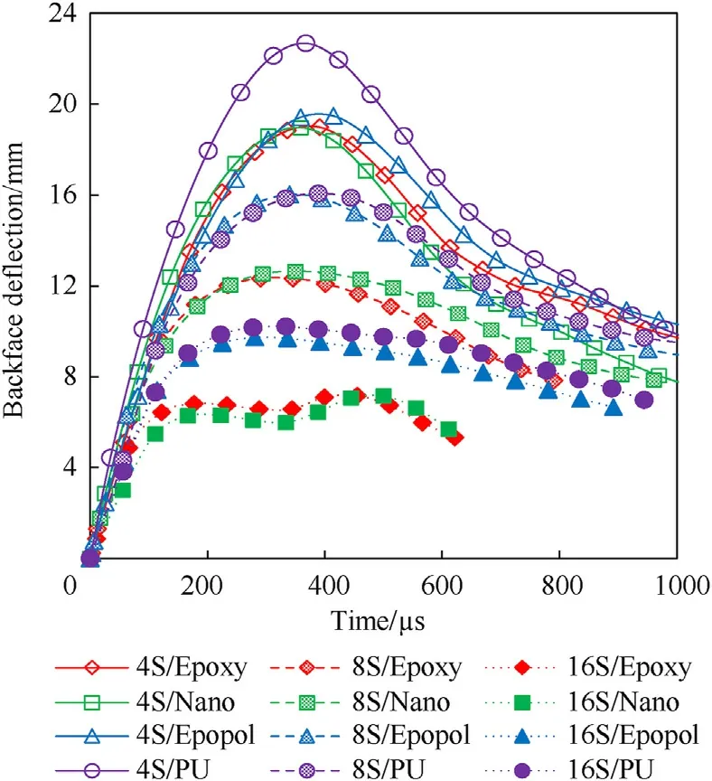
Fig.13.Back face central deformation histories of the composite samples subjected to the nominal impact energy level of 45 ± 5 J.
5.4.Damage assessment
Fig.14 shows the photographs of selected samples under transmitted light after impact,from which the extent and pattern of damage were visualised and compared.It should be mentioned that the planar damage area was the superposition of fibre breakage,matrix cracking,fibre/matrix debonding,and delamination from all the layers.The degree of blackness indicates the degree of damage through the thickness.All these damage modes were observed in the composite specimens after impact;however,the used light transmission approach was not able to quantify the extent of each damage mode.Particularly,for measuring the delamination areas at different interfaces between adjacent layers,it will require other advanced damage detection methods,such as ultrasonic C-scan and X-ray computed tomography (CT).
It is clear that the 16-ply composites showed different damage patterns at the nominal impact energy of 135±3 J.The 16S/Epoxy laminate exhibited a damaged area of oblong or “peanut” shape with its long axis in the vertical direction and concentric to the impact point.The damage around the perforation region was much more severe.This oblong damage shape has been commonly observed in rigid structural composites such as GFRP laminates[37]and CFRP laminates [38]subjected to high-velocity impact.There were severe shear cracks propagating from the perforation zone along the two reinforcing directions.The 16S/Nano laminate showed a similar damage pattern but a smaller area,which indicates that the addition of nano-reinforcements toughened the epoxy resin and increased the resistance to impact-induced damage in the composites.
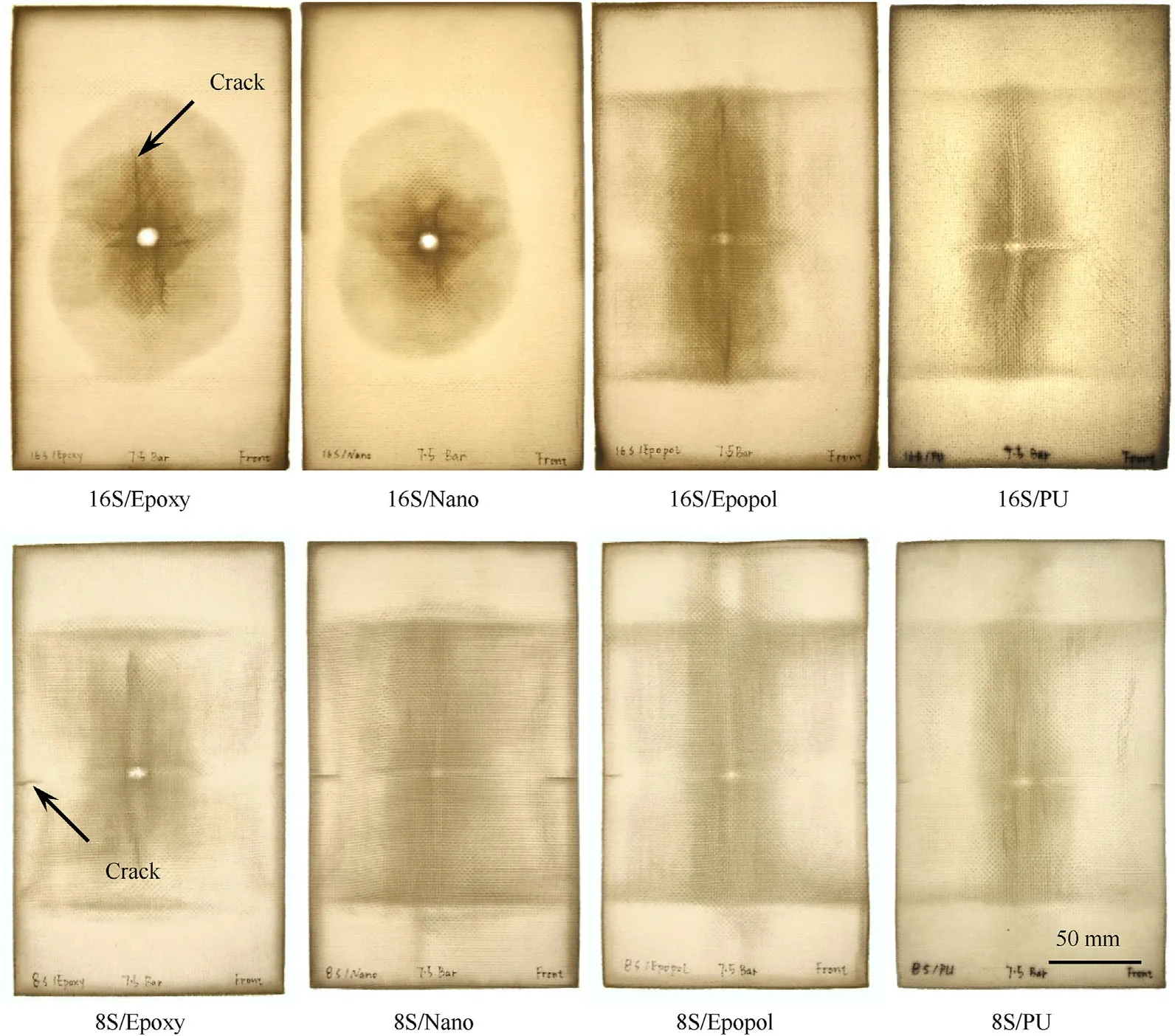
Fig.14.Light-transmission photographs showing the extent and pattern of impact-induced damage in selected composite samples subjected to the nominal impact energy of 135 ± 3 J.
However,a distinct damage pattern was found in the 16S/Epopol and 16S/PU laminates which had a lower bending stiffness and behaved in the membrane stretching mode,as shown in Fig.12(b).A vertical damage zone consisting of fibre-matrix debonding,cracking of the matrix and delamination propagated all the way up to the clamped horizontal edges.There was a visible cross-shaped damage pattern,which was attributed to the stretching of orthogonal primary yarns.Moreover,damage along the horizontal clamped edges was also observed as a result of the transverse deformation wave reaching the clamped edges.The 16S/PU laminate exhibited lower damage(smaller damaged area)than the 16S/Epopol laminate.For the 8-ply composites subjected to the nominal impact energy of 135 ± 3 J,all the samples had a similar damage pattern to 16S/Epopol and 16S/PU.Because of the reduction of bending stiffness,all these composites deformed in a membrane stretching mode.The vertical strip of damage area was shorter in the 8S/Epoxy sample,the reason for which was the early perforation before the out-of-plane deformation spread to the edges.
Fig.15 illustrates the front and back views of the perforated regions in the Epoxy matrix composites with three different thicknesses subjected to the nominal impact energy of 135±3 J.In the thin 4S/Epoxy laminate,tensile failure of the vertical primary yarns was seen throughout the thickness,while few of the horizontal yarns were broken,which formed a slit perforation shape.The thick 16S/Epoxy laminate had a circular perforation cavity with clean fracture surface on the front,which was the sign of shear failure,while the material on the back face was failed by tension.The perforation shape and size of the 8S/Epoxy laminate fell in between those of 4S/Epoxy and 16S/Epoxy.It is also found that the sizes of these perforation cavities were smaller than that of the projectile,which means the projectile was able to wedge through these cavities without breaking more yarns.
It is noteworthy that the number of broken yarns per ply was distinctly higher in 16S/Epoxy than in 4S/Epoxy and 8S/Epoxy.However,the average energy absorption per ply of the 16S/Epoxy laminate(6.8 J)was much lower than those of 4S/Epoxy(11.8 J)and 8S/Epoxy(11.1 J),as shown in Fig.9.This can be explained from two aspects: firstly,the energy dissipation associated with yarn breakage due to tensile failure is much higher than that due to shear failure;secondly,the larger deformation area helps the thin composites to dissipate more energy per ply before perforation occurs.This novel finding was different from the results elucidated in Lee et al.’s work[18]where the energy absorption was found to be proportional to the number of broken yarns.One possible reason is that a fragment simulating projectile (FSP) was used in their study,so the fibres in the tested laminates were susceptible to failure in shear or cutting by the projectile’s sharp edge.But this study employed a spherical projectile,and different fibre failure modes,i.e.,tensile and shear failures,were observed in different composites depending on the matrix rigidity and thickness.
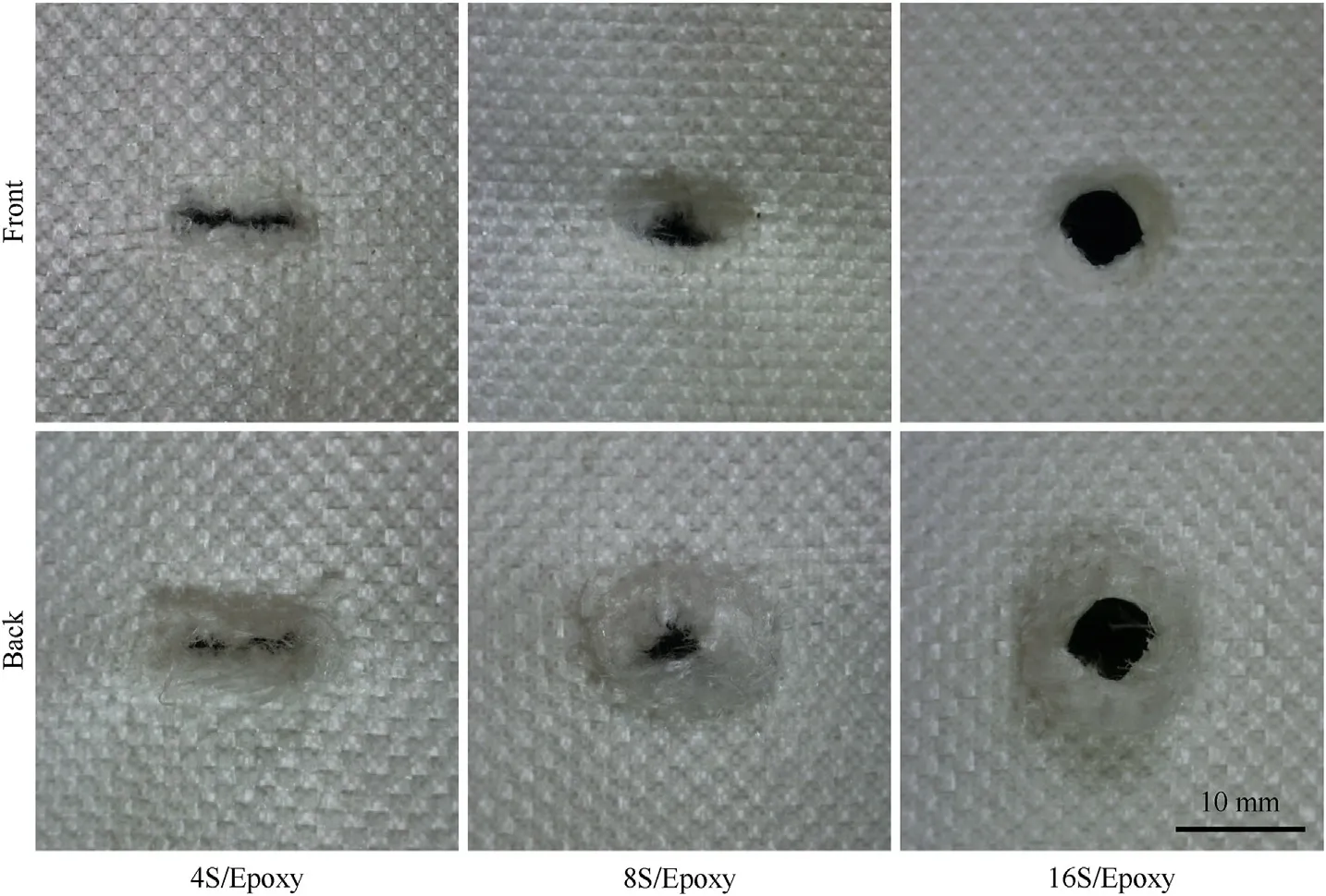
Fig.15.Close-ups of perforation shapes and sizes in Epoxy laminates with different thicknesses subjected to the nominal impact energy of 135 ± 3 J.
5.5.Numerical analysis
5.5.1.Comparing the behaviour of rigid andflexible matrix composites
Fig.16 compares the experimental and numerical transverse deformation behaviour of the 4S/Epoxy composite subjected to impact with 135 J nominal impact energy (or 196 m/s nominal impact velocity).It can be observed that the numerical results agree well with the experimental observations through high-speed photography.The rigid epoxy composite exhibited minimal transverse deformation prior to localised failure at the impact point(at 111 μs).The composite target started failing before the transverse wave reached the clamped edges.Complete perforation was observed at 167 μs.The predicted residual velocity of the projectile(155.8 m/s) was in close agreement with the experimental result(153.6 m/s).
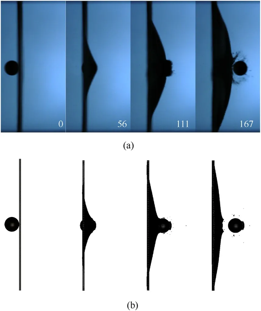
Fig.16.Side view of different stages of the 4S/Epoxy composite subjected to the nominal impact energy of 135 J: A comparison of (a) experimental and (b) numerical results (timestamps are in μs).
The isometric view of the impact process of the 4S/Epoxy target being subjected to the nominal impact energy of 135 J(196 m/s)is illustrated in Fig.17.An isometric view cannot be obtained during the experiments due to the limitations in the setup.Fig.17 reveals that the proposed numerical approach captures the perforation behaviour of the rigid matrix composite 4S/Epoxy realistically.The*CONSTRAINED_SHELL_IN_SOLID contact algorithm used between the fabric shell elements and the matrix solid mesh works appropriately for a composite material under impact loading.Moreover,the implementation of failure has been achieved in both the fabric shell elements and matrix solid elements.
The effective stress and effective plastic strain plots of the 4S/Epoxy composite are shown in Fig.18.It can be observed that the development of plastic strain and effective stress is limited at the impact point and does not spread out away from the impact point,suggesting minimal membrane effect leading to localised failure and comparatively lower energy absorption.The rigid epoxy resin overly constricted the mobility of yarns and the transverse deformation of the composite,which hindered energy absorption by involving a smaller number of yarns.Moreover,a lower amount of energy was absorbed in these rigid resin composites by yarn stretching,which is a main energy absorption mechanism.Similar localised failure was observed at high impact velocities for relatively rigid fabric targets in the recent work by Weerasinghe [29].
Fig.19 shows the side view of the 4S/PU sample being subjected to the nominal impact energy of 135 J (196 m/s).Compared to the rigid 4S/Epoxy sample,the flexible polyurethane resin promoted significantly larger transverse deformation in the 4S/PU composite.The transverse wave upon impact reached the clamped edges in contrast to the rigid epoxy composite target.The transverse deformation behaviour of the 4S/PU composite is captured with reasonable accuracy by the numerical simulation.At 111 μs,however,a slight difference in the shape of the transverse profile is observed.From a side view,the 2D triangular shape of the pyramidal transverse wave had a lower height and a wider base in the experiment than the numerical prediction.This is most likely due to the differences in the matrix material properties used in the FE modelling.The material properties of polyurethane materials are highly sensitive to strain rate.Thus,the quasi-static material properties(such as those provided by the manufacturer)cannot be used in modelling the impact response.Due to the lack of high strain-rate data of the specific polyurethane variant used in the present experimental work,the stress-strain data (see Fig.6) of flexible polyurethane under a range of strain rates provided by Somarathna et al.[34]was used in the FE modelling.
Furthermore,the back face central deformation histories measured experimentally and numerically are collated,as shown in Fig.20,for both the 4S/Epoxy and 4S/PU composites under the nominal impact energy level of 45 J.Discrepancies are observed between the experimental and numerical results in terms of rising slope and maximum deformation.Again,this results from the slightly different material properties used in the simulations.Characterising the mechanical properties of the used epoxy and polyurethane resins at different strain rates as the input into the FE models will improve the accuracy of the simulation.In general,the results indicate that the proposed numerical modelling approach is suitable for simulating the impact behaviour of textile composites with rigid or flexible matrices.
The effective stress and effective plastic strain plots of the polyurethane matrix composite are shown in Fig.21.It can be observed that the development of plastic strain and effective stress propagated to the clamped edges,whereas the strain and stress were localised around the impact point in the rigid epoxy composite.The high flexibility of the polyurethane resin facilitated the transverse deformation of the 4S/PU composite,which instigated global deformation of the target,thereby leading to higher energy absorption by membrane effect,pyramidal deformation and yarn stretching.The flexible resin also prompted the energy absorption process using a significantly larger number of yarns than the rigid matrix composite,which resulted in substantially higher energy absorption.
The projectile velocity histories of 4S/Epoxy and 4S/PU composite specimens subjected to the nominal impact energy of 135 J(196 m/s)are shown in Fig.22.It can be observed that the projectile was decelerated faster by the 4S/Epoxy sample in the initial stage of impact.However,the rigid composite was perforated while the 4S/PU flexible composite deformed further.The hard epoxy resin caused a higher deceleration of the projectile initially,however,also constricted yarn movement and resisted transverse deformation in contrast to the 4S/PU composite.Therefore,the stress development was localised in the vicinity of the projectile,leading to localised failure at an early stage when compared to the flexible composite.
5.5.2.Advantages of the proposed numerical modelling method
In the authors’ previous work,different numerical modelling approaches were studied and proposed.In Weerasinghe [29],a mesoscale modelling approach consisting of solid elements only(Fig.23(b)) was proposed.However,using only solid elements is highly computationally expensive,and high-performance computing (HPC) facilities may be required to facilitate the simulation of multi-layer composites.In Weerasinghe et al.[23],a hybrid modelling approach where Lagrangian solid elements (fabric) and arbitrary Lagrangian-Eulerian (ALE) elements (matrix) were used(Fig.23(a)).However,such modelling methods were found to be extremely computationally expensive due to complicated Lagrangian-ALE interface tracking.

Fig.19.Side view of different stages of the 4S/PU composite subjected to the nominal impact energy of 135 J: A comparison of (a) experimental and (b) numerical results(timestamps are in μs).
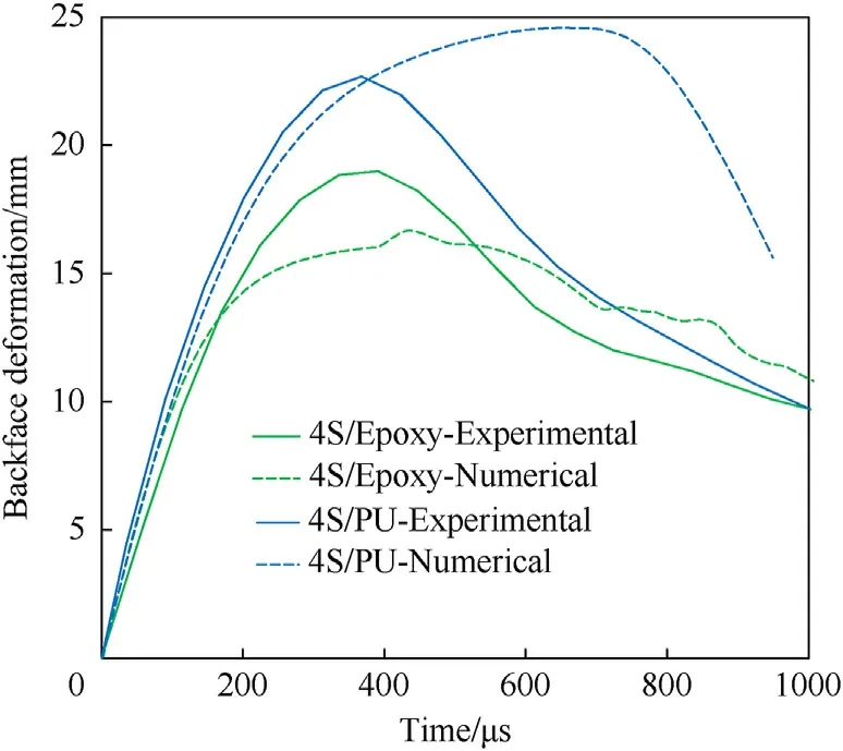
Fig.20.Experimental and numerical back face deformation histories of the 4S/Epoxy and 4S/PU composites subjected to the nominal impact energy level of 45 J.
Using shell elements rather than solid elements for modelling yarns(Fig.23(c))has several additional benefits.Firstly,using shell elements is significantly more computationally efficient than using solid elements.Moreover,allocation of transverse and shear moduli,orders of magnitude lower than the longitudinal modulus,makes solid elements undergo extremely large deformations,thereby causing the minimum edge length of such solid elements to be quite small.Small minimum edge lengths of solid elements cause extremely large computational time.In addition,such solid elements are highly prone to negative volume (negative Jacobian)deformations leading to either erroneous termination of simulations or premature element erosion,whereas shell elements are less prone to undergo negative volumes.Furthermore,hourglass control of solid elements used in mesoscale models is complex,as pointed out in the authors’ previous work [22].Fully integrated solid elements or selectively reduced fully integrated solid elements which can circumvent hourglassing are even more computationally expensive than the default (reduced integrated)solid elements.Therefore,using shell elements (with full integration) is logical and more computationally efficient.
The*CONSTRAINED_SHELL_IN_SOLID keyword,which provides shell fabric-solid matrix coupling,facilitates computational efficiency by constraining acceleration and velocity,and also facilitates modelling of the impregnation of resin into yarns,since the fabric mesh is embedded in the resin mesh.This is not possible in the conventional methods such as those shown in Fig.5(a) and Fig.23(b).The shell-solid interface is not traced in contrast to the*CONSTRAINED_LAGRANGE_IN_SOLID coupling used in Lagrange-ALE interfaces.When tetrahedral elements are used for modelling the matrix,extremely small element sizes are unavoidable at the matrix-fabric interface,resulting in a significantly higher number of elements and smaller timesteps,leading to an extremely longer computational time.Moreover,tetrahedral solid elements can introduce artificial stiffness to the material response due to their element formulation,which makes them unsuitable for modelling flexible matrix composites.
The proposed numerical modelling approach,therefore,presents a computationally efficient,reliable and easily implementable method for modelling both rigid and flexible textile composites in the mesoscale resolution.
6.Conclusions
A series of impact tests were conducted on fabric-reinforced textile composites and neat woven fabrics,and the effects of matrix rigidity,laminate thickness,and impact velocity on the energy absorption,penetration mechanism,back face deformation,and damage pattern have been discussed in this paper.Moreover,a novel mesoscale FE model was developed to predict the dynamic mechanical properties of textile composites with different matrices.More importantly,the effects of matrix rigidity on the failure mechanisms of textile composites were further analysed by numerical simulations.The following conclusions could be drawn from the results:
(1) The impact response of textile composites was strongly dependent on the matrix rigidity and thickness.In general,as the matrix rigidity and thickness increased,the impact response gradually changed from a membrane stretching mode to a plate bending mode,which led to inferior penetration resistance and lower energy absorbing capacity.
(2) The membrane stretching mode was a more effective way to utilise UHMWPE fibres because the material was highly stretched and failed in tension,and it was shown that the average energy absorption per ply was much higher in this mode although the number of broken yarns was smaller.
(3) Examining the back-face deformation with the high-speed camera revealed that very little difference in the deformation was seen for thin composites irrespective of the matrix used.Whereas,as the composite thickness increased,the peak deformations decreased for all the samples,and the history curves started to diverge and form into two groups,viz.composites with rigid resins and those with flexible resins.
(4) Composites with flexible resins had higher penetration resistance and energy absorption but larger back face deflection than those with rigid resins under the tested conditions in this study.So there is a trade-off between the penetration resistance and deformation resistance of textile composites for impact protection.Out of the four tested resins,the polyurethane resin provided the composites with the best penetration resistance.
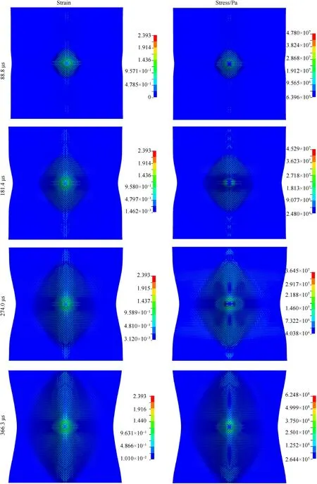
Fig.21.Stress and strain contours at different stages of the 4S/PU composite subjected to the nominal impact energy of 135 J.
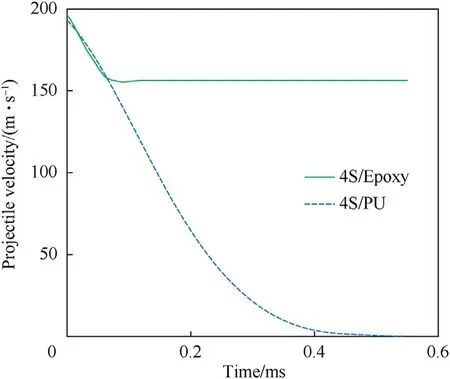
Fig.22.Projectile velocity histories of 4S/Epoxy and 4S/PU composites subjected to the nominal impact energy of 135 J (nominal impact velocity of 196 m/s).
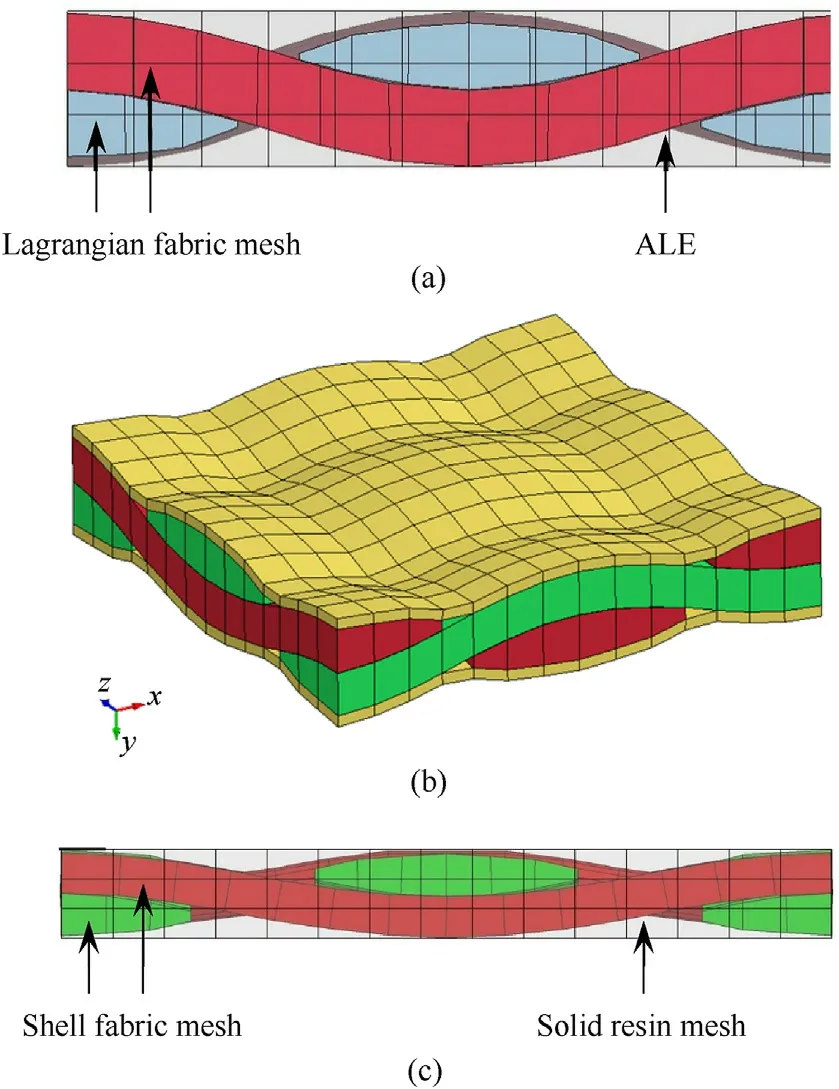
Fig.23.Different composite modelling approaches used in the authors'previous work and the present work:(a)solid Lagrangian fabric mesh embedded in ALE matrix mesh,(b) solid fabric mesh and solid matrix/coating mesh,and (c) shell fabric mesh constrained with solid matrix mesh in the present work.
(5) The addition of triblock copolymer nano-reinforcements toughened the epoxy resin and therefore improved the penetration resistance and reduced the damage extent of composites to some degree.But this improvement appeared to disappear when taking areal density into consideration;the specific energy absorption of composites with nanoreinforcement toughened epoxy was lower than those with pure epoxy in the perforated cases.
(6) The novel approach proposed for modelling textile composites in the mesoscale resolution replicated the impact response of both rigid and flexible composites with high computational efficiency.Moreover,it was revealed that the stress and strain development was localised in the vicinity of the impact location for rigid composites leading to localised failure.In contrast,stress and strain development was spread out in the flexible composite leading to membrane effect and higher energy dissipation.
The results in this paper are informative for the engineering design of body armour and helmets because they show a promising way to control the impact behaviour of textile composites.The data here fills the gap in the literature and is vital for a better understanding of the effects of matrix rigidity on the impact behaviour of textile composites.The developed mesoscale FE model can be an appropriate new methodology for future investigations on the mechanical behaviour of other textile composites under various loading conditions,with high computational efficiency.
Declaration of competing interest
The authors declare that they have no known competing financial interests or personal relationships that could have appeared to influence the work reported in this paper.
Acknowledgements
The authors appreciate the contribution to this work by Dr Krishna Shankar,who was retired during the writing of the paper.The authors acknowledge the Impact Dynamics Laboratory at UNSW Canberra for providing the experimental services described in this paper.
Appendix A.Supplementary data

Table A1 Experimental results of impact velocity vs.residual velocity for different samples.
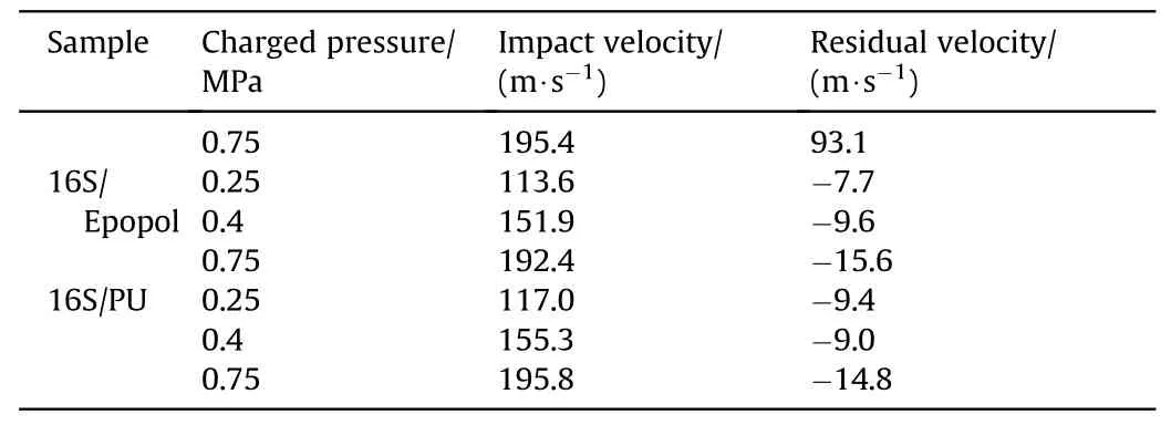
Table A1 (continued)
杂志排行

Defence Technology的其它文章
- Dual Attribute Adversarial Camouflage toward camouflaged object detection
- A bi-population immune algorithm for weapon transportation support scheduling problem with pickup and delivery on aircraft carrier deck
- One-step green method to prepare progressive burning gun propellant through gradient denitration strategy
- Benchmark calculations and error cancelations for bond dissociation enthalpies of X—NO2
- GO/HTPB composite liner for anti-migration of small molecules
- Resilient tightly coupled INS/UWB integration method for indoor UAV navigation under challenging scenarios