Burning rate analysis of laser controlled 5-aminotetrazole propellant
2023-05-06NianbaiHeRuiqiShenLuigiDeLuaLizhiWuWeiZhangYinghuaYe
Nianbai He ,Ruiqi Shen ,* ,Luigi T.DeLua ,Lizhi Wu ,** ,Wei Zhang ,Yinghua Ye
a School of Chemical Engineering,Nanjing University of Science and Technology,210094,Jiangsu,China
b Institute of Space Propulsion,Nanjing University of Science and Technology,210094,Jiangsu,China
c Space Propulsion Laboratory (Ret),Department of Aerospace Science and Technology,Politecnico di Milano,20156,Milan,Italy
Keywords:5-Aminotetrazole (5-ATZ)Laser-augmented chemical propulsion(LACP)Non-constant burning rate Micro computed tomography (MicroCT)Non-planar burning surface
ABSTRACT As an innovative propulsion technique,laser augmented chemical propulsion (LACP) seems superior to the traditional ones.However,the corresponding combustion theories have still to be ascertained for LACP.Burning rate of 5-aminotetrazole (5-ATZ) propellant has been studied by testing pressed samples under different combustor pressures and laser powers.Based on micro computed tomography(MicroCT),an advanced thickness-over-time (TOT) method to characterize the regression of the produced nonplanar burning surface is established.Because of a shell structure covering the combustion surface,the burning rate of the implemented 5-ATZ propellant is not constant during laser ablation.Resorting to functional fitting,a new law of non-constant burning including the effect of the observed unique burning surface structures is proposed.Accordingly,applicable combustion conditions of 5-ATZ based propellants have been preliminarily speculated for future research activities.
1.Introduction
External laser radiation has been applied for experiments and investigations on energetic materials for decades.Benefiting by its high safety and precision,laser ignition is highly applicable to propellants and explosives [1—4].Owing to the continuous assistance of external radiation source,evaporation and ionization on the propellant surface results in a specific impulse much higher than expected from traditional chemical propulsion.Instead of an autonomously sustained combustion,ignition and interruption of combustion process can be controlled by external laser regulation.At the 6th European conference for aeronautics and space sciences[5]in 2015,“laser-augmented chemical propulsion (LACP)” was proposed as the name of such innovative propulsion technique.Indeed,differently from laser propulsion [6],as stressed by the word“chemical”,the thrust of this innovative propulsion is mainly generated by a chemical propellant.
Correspondingly,new combustion characteristics are required for the applicable propellants.For example,the combustion products must be clean enough to avoid energy loss over the laser path,and the energetic formulation must permit sustained combustion only under laser impingement while it should rapidly extinguish without radiation.Nitrogen-rich compound could be the desired propellant ingredient,because black smoke in combustion products is effectively reduced by increasing the nitrogen content in the propellant formulation.The fraction of nitrogen in aminotetrazole is the highest among all organic compounds,and in particular 5-ATZ features a content of 82.3 wt%.Fig.1 shows the chemical structure formula of 5-ATZ[7].In addition,5-ATZ is commonly used as gas generating composition due to its high thermal stability and non-self-sustaining combustion features.
In the early studies of LACP,under laser ablation in nitrogen,unique bulges[8]were observed for a propellant manufactured by pressing mixed powders of 5-ATZ and carbon.Recently,a further investigation [9]was conducted on the same propellant,in which two kinds of unique structures and a unified formation mechanism were proposed,as illustrated respectively in Fig.2 and Fig.3.Relevant denominations,definitions and mechanisms of Figs.2 and 3 are also applied accordingly in this paper.

Fig.1.Chemical structure formula of 5-ATZ.
As illustrated in Fig.2,“burning surface” is the major reaction area of 5-ATZ decomposition;“shell”is the extra structure covering the“burning surface”;“boundary vesicles”are numerous miniature cavities gathering at the boundary of the shell and burning surface;“central cavity”is the cavity filled by gas products embraced by the shell,burning surface,and boundary vesicles during laser ablation;“no reaction zone” or “unreacted propellant” is the propellant portion underneath burning surface where no active chemical reactions is taking place;“extensional edge” is the main distinction between the two surface structures,on the periphery of the edge extension structure oriented to the opposite direction of the impinging laser beam.
As shown in Fig.3,during the initial stage of laser ablation,decomposition reaction and surface structure are the same for both kinds of burning surface.Solidification products of 5-ATZ decomposition remain above the burning surface and form the shell.While the reaction extent of the shell gets higher,subsequent gaseous products are retained beneath and form the central cavity.The margins of the shell form the new gas passage as numerous boundary vesicles because of relatively low reaction extent.With higher environment pressure,the central cavity is limited to smaller volumes,while the margins of the unreacted propellant deform moderately and form the “extensional edge”.
Fig.2.The two kinds of burning surface configuration under investigation and their corresponding structures identified by MicroCT reconstruction:(a)and(b)Bulge Surface;(c)and(d)Edge Extension Surface.Pictures(a)and(b)respectively present 3D and axial sectional views of Bulge Surface under the test conditions of 100 kPa and 10 W.Pictures(c)and(d)respectively present 3D and axial sectional views of Edge Extension Surface under the test conditions of 400 kPa and 4 W.The regions and corresponding customized definitions of both structures are labeled with different colors in (b) and (d) [9].
Fig.3.Brief schematic of the unified formation mechanism for both burning surfaces structures [9].
Systematic research of single ingredients applied as components in propellant formulation is necessary [10],especially for an innovative propulsion technique.While the companion investigation [9]has revealed a unified formation mechanism for the observed unique burning surface structures,this paper focuses on their impact on the burning characteristics of 5-ATZ propellant during laser ablation.For simplicity,in this paper the reaction of 5-ATZ propellant ablated in nitrogen by laser is also called combustion or burning.
2.Experimental
2.1.Propellant preparation
Powders of 5-ATZ and carbon were mixed evenly,with mass ratio of 19:1.The component 5-ATZ was ground by ball-milling and sieved to particles size between 75 and 150 μm.Ground 5-ATZ looks like a white powder and scarcely absorbs laser energy,hence carbon powder is added as a laser absorption agent.Carbon was purchased as micron-sized black particles in the range 10—40 μm.Without any oxidant,oxygen balance does not apply for this formulation.After completely drying the mixed powders at 80°C,crystal water was removed from 5-ATZ.The mixed powders were pressed into cylindrical samples of 6 mm diameter under a pressure approximately equal to 173.3 MPa(pressing was carried out vertically using a hydraulic press for which a setting of 500 kg pressure was selected).The pressed samples so obtained feature a length of 12 mm±50 μm and an average density of 1.45 g/cm3.In this paper,if not otherwise stated,“propellant”refers to the above formulation of 5-ATZ single reacting ingredient modified by the addition of carbon.
2.2.Combustion operating conditions
Combustion of pressed propellant samples was tested in a pressurized combustor under a steady nitrogen flow and no oxygen;see Fig.4.
The combustor is made of stainless steel with a theoretical maximum operating pressure of 2 MPa.The combustor internal volume is approximately 500 cm3and large enough to keep a steady gaseous environment of nitrogen flow during combustion.
Combustion in static environments excludes the effects of gas flowing,but causes laser power attenuation due to the smoke of combustion products.Thus,a nitrogen flow is enforced for combustion experiments.Before turning on the laser power,nitrogen flows through the combustor for 60 s to expel the oxygen present in the combustor.Designed combustor pressurespwere 50,100,150,200,250,300,350 and 400 kPa.A minimum pressure of 50 kPa was necessary to keep oxygen outside the combustor.The maximum pressures of 400 kPa was out of consideration for safety and steady nitrogen supply.During combustion,gaseous pressure inside the combustor is measured by a sensor and recorded.Due to the flowing nitrogen in combustor,the actual pressures were not perfectly steady.For each test,the initial pressure was set a little higher than the established pressurepidealin experimental design.During laser ablation,the intrinsic pressures slightly decreased with time.For each combustion experiment,prealwas recorded as the average pressure value between beginning and ending of combustion.Thus,the experimental record ofpidealis slightly different from the established value ofpideal,but the difference was less than 3 kPa for all conditions.In the experimental data processing with environment pressure regarded as constant,pidealis applied instead ofpreal.
Propellants were ablated by a semiconductor laser,with wavelength of 808 nm and a collimating laser beam of 6 mm diameter.The enforced laser powersPare 3,4,5,6,7,8,9 and 10 W in CW laser mode.All laser beams are subjected to energy attenuation at the combustor entrance and reflectivity by the propellant surface.Both losses are taken into account.Reflectivity on the planar surface of pure 5-ATZ grain is almost 100%,but by adding 5% carbon,the reflectivity reduces to 29.92% at 808 nm wavelength.3 W is the minimum laser power to ablate propellant.The maximum laser power considers the power decrease in time:in the CW laser mode of 10 W,the power decrease in 300 s is lower than 0.01 W.
2.3.Combustion experiments
Three groups of combustion tests were designed and performed in this work:
Group 1.Combustions of 120 s for all test conditions,including 64 combinations of combustor pressure and laser power.
Group 2.Combustions of times series for four selected conditions (called “corner” conditions,as explained in Sec.3.2),which are 3 W at 50 kPa,10 W at 50 kPa,3 W at 400 kPa,and 10 W at 400 kPa.The complete times series contain 5,10,15,30,45,60,90,120,180 and 300 s of laser impingement.
Group 3.Combustions of 180 s,with the same combination of conditions as Group 1.
Each experimental group shared the same process: experimental design,propellant preparing,combustion experiments,MicroCT measurements and data analysis.Turnaround times for each group was about 60 days.Experimental designs of Group 2 and Group 3 were based on the results of former groups.Propellant preparation and combustion conditions for the three groups remained the same as much as possible.To weaken the impact of time,the required experimental tests were fully repeated for each group.
Fig.4.Schematic of the experimental combustion system.
Individual differences during combustion were often significant among propellants tested under the same experimental condition.To obtain reliable experimental data,each combustion test was repeated five times in average.
2.4.Micro computed tomography
Benefiting by the high penetrability of X-ray,computed tomography (CT) is widely used for disease detection in modern medicine.Furthermore,3D perspective of testing sample could be reconstructed with scanning images of various rotation angle by the technique of micro computed tomography (MicroCT) [11].MicroCT measurement is currently applied for modern research activities in medicine and biology [11,12],and its feature of nondestructive measuring is highly suitable for this investigation.Due to the non-self-sustaining features of LACP,all propellant remains of combustion experiments could be collected after natural cooling down,and then measured by MicroCT.
3D images of testing sample could be reconstructed with high resolution based on MicroCT measurement [11].Higher resolution depends on a larger quantity of scanning images and higher magnification of phosphor-detector,with both factors controlling the scanning time of a single measurement.Considering the amount of propellant remains from combustion experiments,and the optional requirement of images mostly for measurement of position and distance,a relatively low-resolution procedure was chosen for most CT measurements in this research.As an example,Fig.5 shows negligible differences between two reconstructed perspectives of the same propellant remain using different resolutions(5 min and 180 images vs.47 min and 1800 images).Despite the visual difference,the measurement distance is not affected by the enforced resolution.
2.5.Measurements for non-planar burning surface
In the search for higher accuracy,a general survey of burning rate measurement methods for solid rocket propellants was conducted by an international team [13,14].A variety of experimental techniques was examined grouped in two categories: thickness over time (TOT) and mass balance (MB) techniques,each with its own procedure protocol and accuracy issues.TOT techniques measure burning rates directly from the sample burned thickness;MB techniques deduce burning rates indirectly from a mass balance in the combustion chamber with a chocked nozzle.While in traditional chemical propulsion the propellant burning surface can often be considered planar,under laser ablation,due to the Gaussian distribution of energy in the laser beam,burning surfaces are usually concave.Fig.6 shows a non-planar burning surface of 5-ATZ based composite propellant examined by MicroCT.This configuration makes difficult evaluating the burned thickness of the sample under test and thus neither TOT nor MB techniques are directly applicable.
In a carefully designed experimental apparatus of laser-driven combustion research [2]with applicable modification of laser path,the ablated sample was located in the region with relatively uniform distribution of laser energy to obtain planar burning surface.Such configuration is not applied in this paper due to the requirement of higher energy,which is harder to keep constant for minutes during each single experiment.
Fig.5.Reconstructed 3D perspectives of the same propellant remain with different resolutions and MicroCT with phosphor-detector unchanged.Both profiles were located with same sectional position.
Fig.6.Non-planar burning surface of 5-ATZ based propellants by MicroCT reconstruction.
The simplification of burning surface treated as planar in propellant samples subjected to laser radiation brings a difference between measured and actual values of burning distance,and the difference becomes noteworthy with lower burning rate.In general,the average burning rate of 5-ATZ propellant is extremely low due to the deficiency of oxidant in the formulation.
Mass burning rate by measuring weight loss [15]is an alternative method used when other techniques are not feasible.However,for the 5-ATZ propellant,weight loss during combustion is insignificant due to the extremely low burning rate,and the shell structure with high compactness has a strong impact on measuring the weight of propellant remain.
Hence a precise treatment of the non-planar burning surface is required,accounting for the unusual burning surface structures.Based on advanced diagnostics,an innovative variant of the TOT techniques is proposed according to the following procedure.The burned thicknessDbof the propellant sample is evaluated by MicroCT measurements,as shown in Fig.7.Considering that propellant remains are prone to crack in the no reaction zone underneath burning surface (unreacted propellant) during transportation,both the initial length of the propellant sample before laser ablation and the final length of propellant remain are measured by micrometer,and respectively recorded asLiandLf.
The value ofLfmight be larger thanLidue to the burning surface configuration.Since a concave burning surface is caused by uneven distribution of laser power,the deepest position on the concavity indicates the region of highest laser power density and can be regarded as the reference point for the actual burning surface.The height between the top of propellant remain and the actual burning surface,Hin,can be measured by MicroCT.Then,the burning distance can be calculated as:
BothLiandLfare measured before transportation of the propellant remains,while cracks underneath burning surface does not affect the measurement ofHin.Therefore,Dbis not affected by possible errors due to sample transportation and cracking.
Fig.8 illustrates the MicroCT measurement ofHinfor the same propellant remain shown in Fig.2(a)and(b).In the MicroCT image reconstruction software,four views from different sections are exhibited,respectively: 3D view on upper left,section-xzview on upper right,section-xyview on bottom left,and section-yzview on bottom right.The coordinate lines in each plane section indicate the positions of the two other plane sections.The image reconstruction software divides the entire field into cubes.The number of slices to divide cubes in axial directions were respectively 972 inxaxis,972 iny-axis,and 768 inz-axis.The value of distance between slices is certain with samples scanned by MicroCT.Altering axial directions changes the number of slices,with the value of distance between slices fixed.In this illustration,see pictures(c)and(d),the distances between two slices are all 14.6 μm in each axis,and henceHin=(324—129) *14.6=2851.6 μm.
As shown in Fig.7,Hbis another important measurement in MicroCT reconstruction.Hbrepresents the height of central bulge,measured as the distance between the top of shell and actual burning surface.In the Bulge Surface structure,HinequalsHb,since the top of central bulge is also the top of propellant remain.For the Edge Extension Surface structure,the top of propellant remain usually is on the extensional edge,therefore the locations of three slices in section-xyview are required to calculateHinandHb.Fig.9 illustrates the MicroCT measurement ofHinandHbfor the same Edge Extension Surface shown in Fig.2(a)and(b).In this case,see pictures (a) and (b),Hin=(505—284)*14.6=3226.6 μm;Hb=(505—404)*14.6=1474.6 μm.

Fig.7.Measurement of Db for both surface structures.
Fig.8.Measurement of Hin in MicroCT reconstruction.
However,burning surfaces are not always perpendicular to the axial direction of propellant remain,and obvious errors ofHinandHbcould be caused by a measurement without correction.Fig.10 shows an example of coordinate system adjusting for slant burning surface:the entire burning surface is seen to exactly cover the propellant in section-xyview after appropriate adjustments.
In addition to the complexity of individual burning surface in practice,measurements ofHinandHbrequire operations on 3D perspective by image reconstruction software.Hence,all measurements involving MicroCT in this paper are manually processed,to avoid possible mistakes by applying automatic algorithm.
3.Burning rate analysis and results
3.1.Combustion experiments of 120 s
In LACP,the burned thickness for a certain burning duration can be conveniently measured by turning off the laser radiation.In Group 1 of combustion experiments,propellants were ablated for a total timetb=120 s in a combustor with flowing nitrogen.Fig.11 shows the profiles of the obtained burning surfaces.All profiles in Fig.11 were collected by MicroCT reconstruction,and randomly chosen from propellant remains of five experiments repeated under the same combustion conditions.Edge Extension Surfaces occurred for high combustor pressure,but not exclusively.For example,profiles of 9 W at 350 kPa and 6 W at 350 kPa represent Bulge Surfaces.
For Group 1,Hinwas measured as described in Sec.2.5,and totalDb(measured over the total timetb)was obtained with Eq.(1).For a better visualization,Fig.12 shows the correlation between totalDband both combustion conditions for Group 1 as a contour map.The value of each totalDbis averaged over five experimental runs.
The regularity of totalDbis obvious in Fig.12,whereDbrapidly increases on the upper left corner,but such regularity is no longer shown with a single control variable.For Group 1,the dependence of totalDbonP with pideal=const is shown in Fig.13,while the dependence onprealwithP=const is shown in Fig.14.With a single control variable ofPorpideal,both dependences are complex to describe with a consistent pattern.
Fig.9.Measurements of Hin and Hb for an edge extension surface.

Fig.10.Adjustment of coordinate system for slant burning surface.

Fig.11.Profiles of burning surfaces in Group 1.Abscissa indicates the nitrogen pressure p,and ordinate indicates the laser power p.

Fig.12.Contour map of total Db for Group 1.The x-axis represents the established combustor pressure (pideal), y-axis represents the laser power p, Db is represented by colors on the corresponding position of the contour map.
Based on usual expectations,burning rate commonly increases with increasing laser ablation power,because the reaction rates on burning surface augment due to the additional heat input from the external radiation.In recent investigations of LACP[16,17],burning rate of two kinds of 5-ATZ based propellants was found increasing linearly with laser power under gaseous environment of atmospheric or slightly higher pressure.However,totalDbhardly increases with higherPin Fig.13(g),and even it slightly decreases in Fig.13(h).Resorting to the Vieille’s (or Saint Robert’s) law [18]commonly used in traditional chemical propulsion,the dependence in Fig.14 fits a simple linear expression,more precisely known as the Muraour law [19].Furthermore,the linear dependences in Fig.14 are mostly different from Sinditskii’s study[20],where the burning rate of 5-ATZ increases with increasing pressure above 1 MPa without external heat flux.
Thus,experimental burning rate results for LACP indicate a peculiar dependence on operating conditions.For instance,for a double-base solid propellant burning rate was found to decrease for increasing laser power density in the range 0.3—0.7 W/mm2with a back pressure of 0.6 MPa [21].Likewise,the burning rate dependence on back pressure was unusual for the common composite propellant AP/HTPB (ammonium perchlorate/hydroxylterminated polybutadiene) [22,23];see Fig.15.Both experimental results show the burning rate rising with increasing back pressure in the range 1—100 kPa,but picture (b) presents a decreasing tendency for pressures above 100 kPa,while burning rate is typically increasing with higher pressure in traditional chemical propulsion without laser assistance.
3.2.Combustion experiments for the four corner conditions
In traditional propulsion,under neutral burning conditions,rcan be considered constant with burning timetand calculated viaDb(TOT technique).In a research of laser-assisted combustion[22],constant burning rate was also obtained in experiments with HTPB/AP composite propellant.But for 5-ATZ,because of its unique burning surface structure,burning rate is variable with time.Based on Sec.2.5,Dbought to increase rapidly at the beginning of laser ablation,when burning surface turned into concave from initial plane.According to the unified formation mechanism of both burning surfaces,see Fig.3,along with the reaction extent of solidification remains increasing by time,insufficient laser power reaching actual burning surface causes the decreasing of burning rate.Hence,for 5-ATZ propellantris not constant and simply cannot be calculated as the ratio total burned thicknessDb/total burning timetb.
To ascertain the pattern betweenrandt,sequential measurements in time ofDb(t)are required.In this work,Dbis measured by MicroCT testing of the propellant remains following the natural cooling off after combustion.To measureDbwith ten different values oftfor a single combustion condition,fifty experiments are required with each burning time repeating each test five times in average.As discussed in Sec.3.1,the complex dependence ofDbrequires processing with both combustion conditions ofPandpcorrelatively.For practical reasons of feasibility,Group 2 only includes four selected operating conditions,called corner conditions with reference to Fig.12.Condition (a) identifies combustion at 10 W and 50 kPa,Condition(b)identifies combustion at 10 W and 400 kPa,Condition (c) identifies combustion at 3 W and 50 kPa,Condition(d)identifies combustion at 3 W and 400 kPa.In spite of limited testing in Group 2,the two typical burning surface structures are both represented,and values ofPandpare both distant enough to distinguishDb.
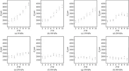
Fig.13.Dependence of total Db on P for Group 1,at constant pideal.

Fig.14.Dependence of total Db on preal for Group 1,at constant laser power P,with the corresponding linear fitting equation.
Fig.16 shows the profiles of propellant remains in Group 2.Profiles in the same column of Fig.16 are different samples,not just one,with different burning times up to 300 s.All profiles were collected by MicroCT reconstruction,and randomly chosen from propellant remains of five experiments repeated under the same combustion conditions and burning time.Each profile includes two views,section-xyview on the left and section-yzview on the right.Deformations of propellants in section-yzview are caused by the coordinate system adjusting for slant burning surface,as shown in Fig.10.
In Fig.16,the forming processes of the two burning surface structures are observed.To visualize the forming processes,Fig.17 shows the history ofHb(t) in time for Group 2 with error bars.

Fig.15.Dependence of the burning rate on environment pressure for AP/HTPB/C=70/30/0.5 wt% (formulation of #1).
SinceHbwas measured by MicroCT after propellant remains cool off,tiny differences might exist between the measured and the actual distance values during laser ablation,because the scorched shell with moderate liquidity might still be able to flow slightly right after laser radiation turning off.Dbis not affected by such measurement difference,due to the offset byLfin Eq.(1),which is also measured after cooling off.Neglecting the tiny measured difference ofHb,Fig.17 shows some regularities of the central bulge on burning surfaces.
Firstly,the growth rates ofHb(t) are highly controlled by the laser power in the preliminary stages.Under laser ablation of 10 W in 5 s,average values ofHbwere respectively 768.9 and 826.4 μm in Fig.17(a)and(b),but only 150.0 and 255.3 μm in Fig.17(c)and(d)with 3 W power.
Secondly,Hb(t) increase reveals insignificant after 120 s for all tested corner conditions.A limiting value ofHb(t) might exist for certain combustion conditions,which means that the central bulge above the burning surface could not enlarge infinitely.
Finally,limiting values ofHb(t) highly relate top.Withp=50 kPa,the maximum measuredHbof single experiments are 2839.7 and 3158.7 μm respectively,but 2058.0 and 2089.9 μm withp=400 kPa.In addition,three of the maximum measuredHb(t)values are not situated at t=300 s,which supports the existence ofHblimit value.
3.3.Function fitting for the four corner conditions
For Group 2,Hinwas measured as discussed in Sec.2.5,andDb(t)was obtained with Eq.(1).The obtained correlationsDb(t)for Group 2 are shown in Fig.18.
For the well-known Vieille’s or Saint Robert’s law of solid propellants[18],the values of the associated a and n constants cannot be predicted theoretically with sufficient accuracy and are determined empirically based on abundant ballistic experiments.Due to the lack of theoretical models,this is even more so for 5-ATZ propellant and fitting functions of Dbmeasures for Group 2 are preferentially applied with equations containing more constants for universality.Considering that the formation mechanism was unified for the two kinds of burning surface structures,in the following subsections a unified fitting functional equation with different constants is sought for.
3.3.1.Functionfitting with simple functions
According to Fig.18(b),(c) and (d),allrvalues visibly decrease along witht.In this respect,a logarithmic function and a power function are applied as fitting equations with monotonic curves:
A linear function was also introduced for comparison:
The fitting results ofDb(t) for Group 2 using Eqs.(2)—(4) are presented in Fig.19 and summarized in Table 1.
Based onin Table 1,Eq.(4)can only be applied to the corner condition (a) of 10 W at 50 kPa.As speculated,constant burning simply does not fit 5-ATZ propellant under most conditions.Considering the standard deviation ofDb(t),Eqs.(2) and (3) are both applicable for all corner conditions in Group 2,with the logarithmic function of Eq.(2) slightly superior in terms of fitting.

Table 1 Fitting results of Db(t) for Eqs.(2)—(4).

Table 2 Fitting results of Db(t)for Eq.(8).
However,the practical combustion characteristics were unexplainable by either Eq.(2)or(3).Horizontal asymptotes do not exist in power function or logarithm function,but do exist in first derivatives of both.Horizontal asymptote for the first derivative of Eq.(2)isy=0.Applying Eq.(3)as fitting function,the constantc3must be in the range (0,1),and the horizontal asymptote for the first derivatives isy=c3.Hence,the finalris very low and could be ignored with fitting functions of Eqs.(2) and (3).
The maximum experimentaltin Group 2 was 300 s,and based on tendencies ofDb(t)in Fig.18(b),(c) and(d),the possibility forrvalue to reduce or approach zero certainly exists with very larget.However,Db(t) of Fig.18(a) still increases distinctly after 120 s,whenHbof Fig.17(a) is stabilized,which means the ablated propellant still maintains a considerable burning rate after the unique structure above the burning surface is completely formed.Associated with the pattern in Fig.12,ris not likely to reduce or approach to zero with Condition (a)or even higherPand lowerp.
3.3.2.Functionfitting with piecewise functions
Power function and logarithmic function were both excluded because of incompatible combustion characteristics.According to Fig.18,the fitting function of burning rate should present an appropriater,which first reduces withtor remains relatively constant,but finally tends to a limit value in a broad range for very larget.
SinceDb(t)is highly affected by the formation of burning surface structure at early burning time,including the effect ofHbmight be logical as the first sub-domain of fitting piecewise function.Therefore,the first sub-domain is applied by Eq.(2) due to the superiorr2.Considering the possible existence ofHblimited value in Fig.17,rcould be constant after the complete formation of burning surface and a linear function as Eq.(4)might be applicable for the second sub-domain.Therefore,the proposed fitting piecewise function is:
wheretprepresents the burning time at the point of matching.Fig.20 illustrates the fitting curves for corner Condition (d) betweenDbandtapplying Eq.(5) with differenttp.
Even though Fig.20 only illustrates one combustion condition with three differenttp,multiple questions were brought up with the application of a piecewise function.
The first question concerns the definition of positiontp.According to Fig.20,the slope of second sub-domain highly relies on the point of discontinuity,which means the limit value ofris strongly affected by the choice oftp.It is fallacious to simply choosetpwith the best correlation coefficient,which could not be compared directly with different data size.Besides,the theoretically optionaltpcould be any moment based on experimental measurements,instead of ten experimental burning times.tpis skeptical and fallible with the insufficient experimental data of Group 2 or from the open literature.
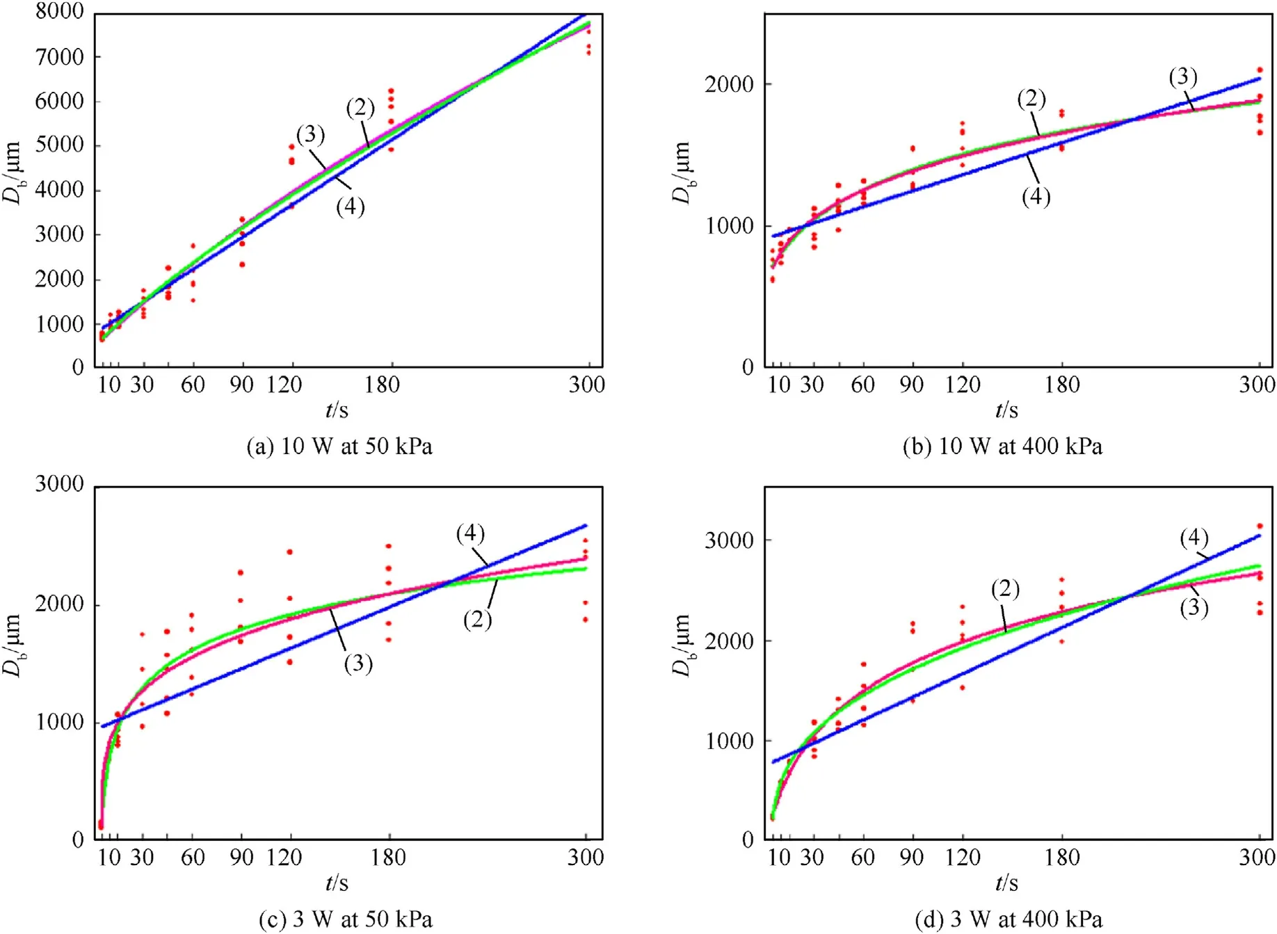
Fig.19.Fitting curves of Db(t) for Group 2 according to Eqs.(2)—(4).Each plot represents a set of corner burning conditions of Group 2.
The second question concerns the method to intersect both subdomains of Eq.(5).According to Fig.20,both sub-domains are distant at the matching point with eachtp.The simplest solution is intersecting both extending sub-domains.Except for the case of extension lines that never intersect,the meaning of burning time at intersection point is deceptive and unexplainable.Another solution is increasing the weight of averageDbattpin the functional fitting and force both sub-domains to intersect at the matching point,but again,such solution is skeptical and fallible without neither insufficient experiments nor open literature data.
The third and most contradictory question concerns Eq.(5):even though a piecewise function is applied to include the effect of burning surface formation,the dependency between positiontpand the measured value of bulge heightHbis diverse.According to the tendency ofDb(t)in Fig.18,a logicaltpof Eq.(5)probably should be earlier than 5 s for Condition (a),but much later for Condition(b),(c) and (d).On the contrary,according to the pattern ofHbin Fig.17,the formation of burning surface structures are completed between 90 and 180 s for all corner conditions.
3.3.3.Functionfitting with polynomial
In the case of functional fitting with piecewise functions,application of constantris reasonable after the burning surface structure has completely formed.In addition,while the formation of burning surface structure is progressive,the precise termination moment of the forming process remains indefinable.The reaction extent of shell is gradually increased with laser ablation according to the unified formation mechanism of burning surface structures in Fig.3.Therefore,rather than a clear-cut succession in time from surface formation to steady combustion,one might envisage that both effects may coexist during the entire combustion period.In this case,burning rate should be:
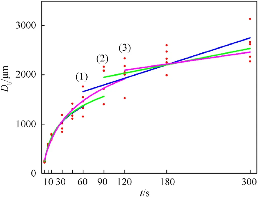
Fig.20.Fitting curves of Db(t)for corner Condition(d)according to Eq.(5).Different tp are indicated in colors and labeled: (1) tp=60 s;(2) tp=90 s;(3) tp=120 s.
whererrepresents the overall burning rate and is expressed like a binomial including two terms,rscandrsfrespectively representing the contributions of combustion and burning surface formation.Accordingly,the expression of burned thickness is:
Considering thatrscremains constant since the beginning of propellant combustion,the applicable linear function forDscin Eq.(7) should pass through the origin of the coordinate system.The limit value ofDsfshould also exist for all combustion conditions in Eq.(7),considering the conceivable existence ofHblimit value in Fig.17.Therefore,the appropriate fitting function forDsfis an exponential function,instead of a power function or logarithm function.The polynomial fitting function forDb(t) turns out to be
whereeis Napierian base,a8-b8e-c8•tis the contribution of burning surface formation,d9•tis the contribution of steady combustion.Fitting results ofDb(t) for Group 2 with Eq.(8) are presented in Fig.21 and Table 2.
Comparing the correlation coefficients in Tables 2 and 1,one can see that Eq.(8) provides with Eq.(2) the best fit of the measured burned thicknesses.
3.3.4.Non-constant burning law
Based on Eq.(8),the non-constant burning law of 5-ATZ propellant for LACP is established,and the time-dependence ofDbcan be expressed as:
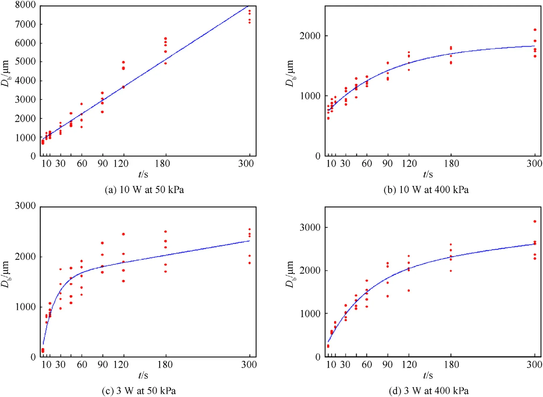
Fig.21.Fitting Curves of Db(t) for Group 2 according to Eq.(8).Each plot represents a certain set of corner burning conditions in Group 2.
Fig.22.Computed histories of r(t).Curves (1),(2),(3),(4) respectively represent Conditions (a),(b),(c),(d) of Group 2.Lines (5),(6),(7) respectively represent the asymptotes of Curves (2),(3),(4).
wheretis burning time,Dbis burned thickness,a,b,c,dare constants valid under certain combustion conditions.Eq.(9) makes sense from both aspects of combustion model and experimental phenomena.The constantais the horizontal asymptote of burning surface formation term,and indirectly represents the impact ofHblimit value,which is highly controlled by the combustion conditionp.Constantcis the approaching rate ofDb(t) to asymptote,and represents the forming rate (or reaction extent increasing rate) of the shell above burning surface.Constantdis the final slope for very larget,and represents the constant burning rate after the burning surface is completely formed.
In Eq.(9),constantbadjusts the curve scale ofDb(t) iny-axis.The author believes the constantbdepends on the propellant formulation and is applicable within a certain range of combustion condition,just like the constants used in the Vieille equation.Only with constantbsettled,the values of constantsaandcof Eq.(9)could change with the representations in propellant combustion.In the functional fitting of Sec.3.3.3,the only experimental measurements ofDbin Group 2 were insufficient to settle constantbfor 5-ATZ propellant,and the specific fitting results in Table 2 were defective.After all,Eq.(9) represents a new form of empirical equation for LACP,especially for the non-constant burning law with unique burning surface.Verification of constantbin Eq.(9) still requires numerous experiments and further research,hence the fitting results of Fig.21 and Table 2 are still applied in the following section.
Fig.23.Computed fraction of rsc/r in time based on Eq.(6).Curves (1),(2),(3),(4)respectively represent Condition (a),(b),(c),(d) of Group 2.
3.3.5.Calculated burning rate
Resorting to the non-constant burning laws discussed in the previous sections,the history of burning rate in time can be calculated as the first derivative ofDb(t)in Fig.21.Fig.22 shows the full time histories ofrcomputed for the four corner tests of Group 2.Because of the derivative,the values of computedrare not accurate at the early burning times.Table 3 compares different values ofr:instantaneous values at 120 s and average values over the time lapse 0—120 s for Group 2 and Group 1 tests.
According to Table 3,bothra0-120are much higher than the instantaneousri120,due to the incongruent assumption of constant burning rate.Thus,the value ofra0-120calculated by the totalDbcontour map of Fig.12 is not suitable to describe the dependence of the non-constant burning rate on the enforced combustion conditions,and an extra group of combustion experiments is required.
Table 3 The value of r by different calculating methods.
For the indicated combustion conditions,ri120is the instantaneous burning rate at 120 s as obtained in Fig.22,while bothra0-120are average burning rates within the first 120 s calculated using the measuredDbof the corresponding experimental groups.
3.4.Experimental design for group 3
The ideal plan for the experiments of Group 3,meant to find out the pattern of burning rates,would be measuringDbfor 64 combustion conditions as already done for Group 2.Since 50 experiments are necessary for a single condition,as explained in Sec.3.2,the total amount of experiments would be impractical.
A more expedient plan for Group 3 is to only find out the final constant burning rates as the constantdin Eq.(9),for all testing conditions.The combustion rate can be considered constant whenrscis significantly larger than thersfin Eq.(6).Fig.23 shows the computed fraction ofrsc/rin Eq.(6)for Group 2.
When the fraction ofrsc/ris higher than 95%,the combustioncan be considered steady,and the correspondingrcan be approximated by constantdin Eq.(9).According to curve(2)in Fig.23,the extrapolatedtwithrsc/rhigher than 95% occurs after 694 s.To determine the pattern of constantdin Eq.(9),measurements ofDbare required in combustion experiments with two particular durations both longer than 694 s for 64 conditions.Except for the interminable experimental periods,the laser power decrement after a long-time of continuous output would be another problem.
Fig.24.Contour map of ra120-180.The x-axis represents the established pressure in experimental design pideal,y-axis represents laser power P,ra120-180 is represented by colors on the corresponding position in the contour map.The contour map is divided into four regions and labeled as Region (A),(B),(C),(D).
Thus,the final compromise plan for Group 3 includes combustion experiments of 180 s with the same conditions of Group 1,and thera120-180can be calculated byDbin both experimental groups.Even thoughra120-180would not be able to visually indicate the final constant burning rate as constantdin Eq.(9),it would represent the average burning rate of a relatively steady phase neglecting the rapid deformation at the beginning of laser ablation.
3.5.Analysis of ra 120-180
In experimental Group 3,propellants were combusted for 180 s andDbmeasured with each combustion condition repeated five times in average as in Group 1.The valuesra120-180were calculated by the corresponding average values ofDbfrom Group 1 and Group 3,and are shown in Fig.24.
Considering the four months interval between Group 1 and Group 3 experiments,the valuesra120-180are calculated by the averageDbof both experimental groups,and are not precise enough for quantitative analysis.Therefore,four regions were identified in Fig.24 based on average burning rates.
In Fig.24,ra120-180of Region (A) is the highest.According to curve(1)in Fig.22,the burning rate of corner Condition(a)rapidly becomes and remains constant after the combustion start,which means even with a similar structure of burning surface,the shell did not exist as an effective obstacle for actual burning surface during laser ablation.Scorched shell ablated by high power laser features higher fluidity,and the shell is much easier to break with weaker restrictions under low environment pressure.In future application of 5-ATZ based propellant for LACP,the ideal combustion condition might be environment pressure lower than 250 kPa with ablating laser power higher than 6 W.
In Region(C),ra120-180is low due to the insufficient laser power.With the increasing of reaction extent on the shell,most laser power is absorbed by the shell and is rarely received by the actual burning surface beneath.According to curve(3)in Fig.22,ra120-180of corner Condition (c) is very close to the final constant burning rate,probably the same as the adjacent condition of Region(C).For 5-ATZ based propellant combusted in a low environment pressure close to atmosphere,a minimum threshold of laser power to break the shell might exist.
Despite higher laser power,ra120-180is so unexpectedly low in Region (B) that even some negative values exist in this area of Fig.24.According to the tendencies of curves(2)and(4)in Fig.23,the difference of final constant burning rate might be more significant between Region (B) and Region (D).
The patterns of burning rate in Region (C) and (D) currently cannot be completely explained and more work is needed.However,experimental results of average burning rate in Fig.24 indicate pattern disparate from common expectations and could be notable in further applications of 5-ATZ based propellant under high environment pressure for LACP.
4.Conclusion
The 5-ATZ propellant proposed for LACP applications features a non-constant burning rate caused by a shell covering the burning surface in anaerobic environment.Along with the reaction extent increasing on the shell,only a fraction of the laser power is received on the actual burning surface after breaking through the shell,and this causes a decreasing burning rate in time.Based on the burning rate measurements by the advanced MicroCT technique discussed in Sec.2.5,a novel burning rate law is proposed accounting for the sample burned thickness in time as reported in Sec.3.The proposed non-constant burning law of Eq.(9) offers the best fitting of the collected experimental data and also makes sense as a combustion model;other fitting laws were attempted but revealed less satisfactory.Since the associated functional fitting is based on only four combustion conditions and due to the lack of literature data,such expression might not be the ultimate empirical equation.However,the selected binomial expression includes both contributions of burning surface formation and steady combustion,and could be verified by carrying out further testing.As to future application of 5-ATZ based propellant for LACP,the ideal combustion condition is low anaerobic pressure with sufficient laser ablation,but combustion characteristics might be different from expectations under high environment pressure.
Declaration of competing interest
The authors declare that they have no known competing financial interests or personal relationships that could have appeared to influence the work reported in this paper.Nothing and nobody
Acknowledgements
This work was supported by the Shanghai Aerospace Science&Technology Innovation Fund (grant No.SAST201363),and also the Fundamental Research Funds for the Central Universities(grant No.30919012102 in part).
杂志排行

Defence Technology的其它文章
- Dual Attribute Adversarial Camouflage toward camouflaged object detection
- A bi-population immune algorithm for weapon transportation support scheduling problem with pickup and delivery on aircraft carrier deck
- One-step green method to prepare progressive burning gun propellant through gradient denitration strategy
- Benchmark calculations and error cancelations for bond dissociation enthalpies of X—NO2
- GO/HTPB composite liner for anti-migration of small molecules
- Resilient tightly coupled INS/UWB integration method for indoor UAV navigation under challenging scenarios