A novel method of utilizing static mixer to obtain mixing homogeneity of multi-species powders in laser metal deposition
2023-02-09JipengCHENShouchunXIEHeHUANG
Jipeng CHEN, Shouchun XIE, He HUANG
a School of Mechanical and Electronic Engineering, Nanjing Forestry University, Nanjing 210037, China
b Nanjing Huirui Photoelectric Technology Co., Ltd, Nanjing 211121, China
KEYWORDS Homogeneity;Laser metal deposition;Multi-species powder;Mixing;Static mixer
Abstract Real-time mixing of multi-species powder challenges Laser Metal Deposition (LMD) of Functionally Graded Materials(FGMs).The current work proposes a novel method of using a static mixer to realize rapid, uniform multi-species powder mixing. Firstly, copper powder and 316L stainless steel powder are selected to complete the powder mixing observation experiment with Scanning Electron Microscope(SEM)and Energy Dispersive Spectrometer(EDS).Secondly,computational fluid dynamics and particle mixing simulation models are used to analyze the flow field and particle motion characteristics in the static mixer. Finally, LMD experiment and metallographic observation are carried out with 316L stainless steel powder and WC powder to verify the feasibility of the static mixer. This study provides a theoretical and practical basis for powder mixing in laser processing with a static mixer.The conclusions can also be applied to other processing fields requiring real-time and uniform mixing of multi-species powders.
1. Introduction
Functionally Graded Materials (FGMs) are a class of advanced materials of which the composition and microstructure change gradually from one side to the other,resulting in a corresponding variation in the properties.1,2This feature enables FGMs to possess the potential advantage of working normally and repeatedly under some harsh conditions, which cannot be obtained by conventional manufacturing technologies such as casting or forging.3,4It is evident from the literature that FGMs have received significant attention due to their graded material properties in aerospace, mineral processing industry, bullet-proof applications, biomaterials, fire retardants,space and defense applications,etc.5Laser Metal Deposition (LMD) is an advanced manufacturing technology that combines rapid prototyping and laser cladding technology.3Thanks to the unconstrained building geometry and flexible control of chemical composition, LMD has become the most suitable method to produce metallic FGMs with a compositional gradient in a flexible fashion.6Moreover, it offers an opportunity to create graded components with different elemental compositions, phases, and microstructures at various locations.7,8For instance, Mahamood and Akinlabi9developed functionally graded titanium alloy composite using optimized laser deposition parameters and proposed that FGM has better micro-hardness and wear resistance. Shah et al.1explored continuously graded stainless steel 316L and Inconel 718 thin wall structures made by LMD process considering the effects of process parameters including laser power levels and powder mass flow rates.Wang Q et al.10deposited functionally graded layers on a titanium alloy Ti6Al4V sheet surface by laser cladding technology. The contents of SiC in the 1st and 2nd layers were 20vol%and 39vol%,respectively.Chen et al.11produced FGMs with the constitution varying from 100 %316L stainless steel to 100 % Inconel 625 alloy utilizing LMD technology. Wang CD et al.12fabricated Ni-Fe FGM using laser metal deposition with a novel process parameter screening strategy by considering powder separation, defects,and power consumption. Lai et al.13conducted laser deposition of a premium hypereutectoid rails grade with 410L stainless steel powder.
In the LMD of FGMs,it is crucial to ensure powder homogeneity. Generally, the multi-species powder is first mixed and then stirred. However, the stirring is time-consuming, taking dozens of minutes or even hours. For example, in Ref. 1, the 316L stainless steel and Inconel 718 powders were weighted separately and then mixed with a mechanical stirrer for 30 min according to the desired weight percentage. In Ref.14, the precursor powders were mixed with a Polyvinyl Alcohol(PVA)binder and then well blended for 20 min and finally deposited on a preheated Ti6Al4V substrate. The pre-stirred multi-species powder usually has a constant composition that does not support real-time powder composition adjustment.Consequently, some new powder feeding systems were proposed. For instance, Ref. 15 introduced a powder feeding system that allows powder composition modification in real-time during the powder mixture. The powder feeder mixer is composed of a special mixing chamber. The homogenous mixing of the different powders occurs by a vibration system working together with mixing blades. This kind of mixer generally has complex structures with large tanks, drive motors, rotating blades, vibration units, and electrical controllers. To simplify the mixer structure, reduce energy consumption, and improve the uniformity of multi-species powder, a novel method of adopting a static mixer for LMD was proposed. Static mixers are energy-efficient devices used in homogenization processes,without moving parts. They are generally more cost-effective than the impellers in stirred tanks. Hence this type of mixer becomes an increasingly popular alternative to conventional mixing.16Some benefits of static mixers in comparison with dynamic ones can be listed as follows: small space required for installation, low maintenance costs, low power consumption,absence of moving parts,short residence times of the fluids, near plug flow behavior of the fluids, efficient heat and mass transfer, good mixing at a low shear rate, and capability of self-cleaning.17-20The simplicity of the static-mixer and excellent mixing performance have attracted many researchers in different areas, such as pharmaceuticals,21water treatment,22,23chemical production,24biotechnology,25,26food processing,27and petrochemistry.28
To investigate the mixing performance of the static mixer,a series of powder spraying experiments and LMD experiments were conducted.To get a better understanding,CFD and powder particle mixing models were employed. The research work helps to build a new powder feeding system and a simple structure for the LMD of FGMs.
2. Experimental methods
2.1. Experimental setup
2.1.1. Static mixer
The static mixers are composed of motionless parts installed in a fixed channel or pipe, as shown in Fig. 1. The fixed part of the static mixer is a pipe with a shrinking nozzle. The motionless interior part comprises a series of spiral blades, each is connected to the other with a cylinder rod (∅2 mm × 2 mm), and two adjacent spiral blades are arranged at 90°. The type of the spiral blade is KSM,29and there are 18 spiral blades in the selected static mixer.The working principle of the selected static mixer is as follows:the powder flow is cut into two parts after passing through the blade,and each part is cut again after passing through the next edge.After this circulation,the powder mixing performance is improved.The static mixer is connected to an adapter with a thread structure(M20 mm × 2 mm). The adapter was self-made, allowing different powder species to flow into the static mixer through the inlets.There are four entrances in the adopter,two of which are available for powder feeding, while the left is reserved and blocked with plugs.
2.1.2. Powder feeding system
As shown in Fig.2,the powder feeding system is built based on a powder feeder and a static mixer. The powder feeder produced by Nanjing Huirui Photoelectric Technology Co., Ltd has two independently controlled powder feeding tanks. The powders in Tank No. 1 and Tank No. 2 are sent to the inlet of the static mixer by a powder feeder and mixed in the static mixer.The static mixer is commercially available and generally used in other applications. Using a ready-made static mixer reduces the cost of the experiment and facilitates the development of experiments. The static mixer is fixed by a clamping device. The powder ejected by the static mixer adheres to a conductive tape which is placed on a motion platform. The reason for using the conductive tape is to meet the requirements of the subsequent Scanning Electron Microscope(SEM) observation. The motion platform is equipped with a lead screw and a controller,which can realize single-axis automatic control and adjust the movement speed, and the rate is set as 20 mm/s in the experiments. The height of the motion platform can be adjusted by the adjusting device.The distance between the nozzle outlet and the conductive is 10 mm.

Fig. 1 Static mixer and adapter.

Fig. 2 Powder feeding system.
2.2. Powder materials
Two different powders, copper powder, stainless steel powder(316L), are used in the experiments. For the convenience of distinguishing, 316L powder adopts spherical particles, while copper powder adopts irregularly shaped particles, as shown in Fig. 3. The average particle size of copper powder is about 150 μm,while that of 316L powder is about 80 μm.The properties of the copper powder and 316L powder are listed in Table 1.

Fig. 3 Powder materials.

Table 1 Properties of powders.

Table 2 Powder feeding parameters.
2.3. Powder feeding parameters
Since the powder is transported to the static mixer with the gas, the powder feeding quantity is affected by the carrier gas flow and the rotating speed of the feeder. According to our pre-experiments, a high carrier flow rate (e.g., 10 L/min)leads to violent flying of powder. Consequently, a constant medium carrier flow rate of 5 L/min was selected.The powder feeding parameters are listed in Table 2.Note that the powder was heated to 100 ℃in a drying oven and kept for 30 min to remove moisture before experiments.
2.4. Experimental characterization
In the experiments,the powder was observed in different ways.The SEM (ZEISS Gemini 300) was employed to monitor the mixed particles adhered to the tape. The Energy Dispersive Spectroscopy (EDS, OXFORD XPLORE30) was adopted to characterize the element distribution of the mixed particles.
3. Numerical simulation
3.1. Simulation model
Simulations are employed based on COMSOL Multiphysics.Fig.4 shows the flow field and particle mixing model of the static mixer.The velocity calculated by the flow field provides the initial value of particle mixing simulation.In the flow field simulation, the flow rate conditions of Inlet 1 and Inlet 2 are the same, which is 5 L/min. In the particle mixing simulation,the two kinds of particles enter from different channels. The average particle size of copper powder and 316L powder is defined as 150 μm and 80 μm, respectively. Assume that there is no interaction between the powders to simplify the calculation,and also take that the powder particles have no influence on the flow field and are released simultaneously, the quantity of copper powder and 316L powder is 1000, separately. Since the model contains a nozzle condition, define an identity boundary pair between the nozzle and its outer space and set the pair to have flow continuity (both in the flow field simulation and particle mixing simulation).The mesh adopts the following parameters: maximum element size 5 mm, minimum element size 1 mm, maximum element growth rate 1.5, curvature factor 0.6, resolution of narrow regions 0.1.

Fig. 4 Simulation model of static mixer with adapter.
3.2. Control equations
The simulation of the turbulent flow field is based on the solution of Reynolds Averaged Navier-Stokes (RANS) equations for the incompressible flows, closed with standard k-ε turbulent model. The standard k-ε model with the standard wall function was used to model the turbulent flow in the static mixer, while the Reynolds averaged Navier-Stokes equations for mass, momentum, energy.30The RANS equations for incompressible flow are written as31

where ρ is density,kg/m3;t is time;U is time-averaged velocity vector, m/s; P is the pressure, Pa; I is the unit matrix; μ is dynamic viscosity, kg/(m·s); μTis turbulent viscosity, kg/(m·s); k is turbulence kinetic energy; F is the Reynolds stress tensor.

The turbulence kinetic energy k and its rate of dissipation ε are governed by31where m is the particle mass; x is the position of the particle;f is the sum of all the forces acting on the particle.
4. Results and discussion
4.1. Experiment results
Fig.5 shows the morphology of the two powders mixed at different magnifications. Both copper powder and 316L powder can be observed. Within the observation range, 316L powder is significantly more than that of copper powder, and copper powder is dispersed in 316L powder. The average size of copper powder is about 80 % higher than that of 316. Accordingly, the average volume of copper powder is about six times that of 316 powders,provided that copper powder is also a sphere. Therefore, the copper powder is less under the same powder feeding channel and the same carrier gas condition.
Although the copper powder and 316L powder are different in appearance,it is difficult to observe the powder distribution characteristics only by SEM photos. Therefore, we use the EDS element mapping method to distinguish the location of different powders, as shown in Fig. 6. Based on EDS element analysis,the copper powder is marked red while the 316L powder is marked green. Furthermore, the image processing tool was used to process the EDS image. After processing, only the shape and position of copper powder are retained and characterized by gray.By observing Fig.6,we can see the distribution characteristics of copper powder in 316L powder.There is no apparent large-scale aggregation of copper powder, which indicates that the powder mixing uniformity can be effectively achieved through the static mixer. Because the powder feeding parameters (gas flow rate and rotary speed)of the copper powder and the 316L powder in each group are the same, the proportion of copper powder is similar.
Furthermore, based on the image processing method, the pixel value is taken as the horizontal axis. The average intensity of the gray target (copper) is taken as the vertical axis.Four groups of average intensity distribution curves are obtained. The calculated standard deviations are 10.5, 11.9,12.3, and 9.6, respectively, which indicates that the position distribution of copper powder is relatively stable.
4.2. Simulation results
The simulation consists of 2 steps. The 1st step is to calculate the flow field in the static stirrer, and the 2nd step is to calculate the powder movement in the flow field. The flow field distribution is shown in Fig.7.When the flow rate of two inlets is 5 L/min, the speed inside the static mixer can exceed 5 m/s,which will be further increased at the outlet nozzle (up to 10 m/s). The velocity distribution in the static mixer crosssection is not consistent. In addition, the flow field in the height direction also changes alternately, which shows the influence of the spiral blade on the flow field.
Figs.8 and 9 show the powder movement in the static mixer at different times (500 ms and 1000 ms). The maximum velocity of powder is about 3 m/s at the outlet of the static mixer,and the powder velocity inside the mixer is less than this value.In the static mixer, the powder particles move along the surface of the spiral blade.The powder has partial radial velocity under the spiral blade’s action, so it tends to approach the cylindrical wall when moving along the axial direction of the static mixer and the velocity near the cylinder wall is higher.

Fig.5 Morphology of mixed particles at different magnification.
4.3. Discussion
4.3.1. Dynamic mixing process of powders
It is essential to analyze the dynamic mixing process of powder particles in the static mixer, which can help understand the mixing characteristics of the static mixer and is conducive to subsequent product design and structure optimization. We selected some specific positions to extract the cross-section particle distribution data, 2 of which are located on the adapter and 9 on the static mixer, as shown in Fig. 10.
Fig. 11 shows the powder mixing process at different locations (t = 2000 ms). It can be learned that the two powders enter from the inlet of the adapter and are mixed under the action of carrier gas. The mixed powder presents agglomeration characteristics and gathers in the central part of the adapter. When the mixed powder passes through the first spiral blade,the aggregation phenomenon is still apparent.The main parts of copper powder and 316L are distributed in the upper and lower space isolated by the blade, respectively. However,the distribution of copper powder and 316L powder tends to be uniform when passing through the second spiral blade,except for local powder aggregation. After the powder passes through more blades,the homogeneity of mixed powder distribution is greatly improved.It can be observed that the density of the mixed powder is higher near the cylinder wall. This is because the blade exerts a radial force on the powder, and the powder tends to move outward,as we have discussed.This phenomenon can also be observed in the experiments using a static mixer with a transparent outer tube. Note that when there are enough powder particles at a specific position in the static mixer, the powder will cover the whole section, but the density at the outer side of the cross-section is still higher than that at the inner side, such as 8 and 9 in Fig. 11.
4.3.2. Effect of spiral blade
The spiral blade is regarded as the essential working part of the static mixer. For further interpretation, a simulation model which does not contain the spiral blades was employed, as shown in Fig. 12. The geometric dimensions and boundary conditions are consistent with the previous model.
Fig.13 shows the powder distribution comparison at different outlet distances (distance from the nozzle outlet). Copper powder and 316L powder are concentrated in the center and gathered obviously when there are no spiral blades inside the static mixer, as shown in Figs. 13(a)-(c). Once the blade is used, the mixing homogeneity of copper powder and 316L powder is improved, as shown in Figs. 13(d)-(f).
Notice that in the case of spiral blades,the first time for the powder to reach the outlet from the inlets is about 500 ms,while in the case of no spiral blades, the first time to reach the outlet is about 320 ms,which indicates that the blades have a particular blocking effect on the movement of the powder.Based on this phenomenon,we wonder whether the blade also significantly impacts the powder feeding rate.
Therefore, an electronic balance with 0.01 g precision was used to detect the mass fluctuation of the powder ejection process after mixing.The sampling frequency is 0.5 Hz.As shown in Fig.14,the spiral blade has no adverse effect on the average powder feeding rate and slightly reduces the standard deviation of mixed powder feeding, which indicates that the spiral blade improves the mixed powder feeding accuracy.

Fig. 6 Distribution of mixed particles.
5. Feasibility verification in LMD
A general laser cladding equipment ‘‘Metal+®” made by Nanjing Huirui Photoelectric Technology Co., Ltd., is adopted to conduct LMD experiments, as shown in Fig. 15. Different powders from the powder feeder are sent to the static mixer for mixing. The outlet of the static mixer is connected to a powder separator by a pipe of 6 mm diameter. The powder separator divides the mixed powder into 3 paths and then sends them to the coaxial nozzle. In the laser melting deposition experiments, 316L powder and tungsten carbide (WC) powder were selected. This is because tungsten carbide has a high melting point and will not melt in laser processing, which is convenient for metallographic observation.
LMD parameters are as follows: laser power 1200 W; carrier gas flow (Ar) 10 L/min; feeder rotating speed 1 r/min(for both tanks); laser scanning speed 480 mm/min. After machining experiments, the machined sample was cut from the cross-section. The metallographic sample preparation was carried out, and then the cross-section was observed by a metallographic microscope.

Fig. 7 Flow field distribution in static mixer.

Fig. 8 Powder movement in static mixer at 500 ms.

Fig. 9 Powder movement in static mixer at 1000 ms.

Fig. 10 Cross sections for powder mixing observation.

Fig. 11 Powder mixing process at different cross sections (t = 2000 ms).

Fig. 12 Comparison models.

Fig. 13 Powder distribution comparison at different outlet distances.
Fig. 16 shows a metallographic diagram in which the WC particles are visible.It can be learned that a relatively uniform WC distribution can be obtained through a static mixer with the current structure, which implies the potential application of the static mixer in multi-species powders mixing in LMD.Note that the powder uniformity obtained by the static mixer may still be lost during the deposition process due to a series of reasons,such as powder deposition rate,laser power and scanning rate,and the characteristics of the molten pool.Since the static mixer employed in this work is not initially used for LMD, the size, structure, material, and type of the motionless part of the static mixer should be further studied or optimized.Also, the optimal powder particle size range (finer or coarser)under a specific static mixer structure needs to be determined.

Fig. 14 Average powder feeding rate.
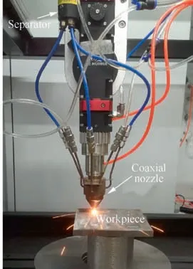
Fig. 15 Laser melting deposition device.

Fig. 16 Metallographic diagram of LMD with a static mixer.
6. Conclusions
A static mixer is proposed for mixing different kinds of powder particles in laser processing. The conclusions are as follows:
(1) The selected static mixer improves the mixing homogeneity of two different kinds of powders, which shows good application feasibility in the field of laser metal deposition.
(2) Under the action of the spiral blade,the powder has partial radial velocity, so it tends to approach the cylindrical wall when moving along the axial direction of the selected static mixer.
(3) The mixed powder is concentrated and gathered in the center when there are no spiral blades inside the static mixer.
(4) The spiral blade has no adverse effect on the average powder feeding rate and slightly reduces the standard deviation of mixed powder feeding,which indicates that the spiral blade improves the mixed powder feeding accuracy.
(5) The static mixer used in the present work needs to be further studied or optimized to meet the specialized needs of laser metal deposition.
Declaration of Competing Interest
The authors declare that they have no known competing financial interests or personal relationships that could have appeared to influence the work reported in this paper.
Acknowledgement
This work was supported by the Jiangsu Industry-universityresearch Institute Cooperation Project, China (No.BY2021078).
杂志排行

CHINESE JOURNAL OF AERONAUTICS的其它文章
- Recent developments in thermal characteristics of surface dielectric barrier discharge plasma actuators driven by sinusoidal high-voltage power
- A review of bird-like flapping wing with high aspect ratio
- Rotating machinery fault detection and diagnosis based on deep domain adaptation: A survey
- Stall flutter prediction based on multi-layer GRU neural network
- Supervised learning with probability interpretation in airfoil transition judgment
- Effects of input method and display mode of situation map on early warning aircraft reconnaissance task performance with different information complexities