Recent developments in thermal characteristics of surface dielectric barrier discharge plasma actuators driven by sinusoidal high-voltage power
2023-02-09XinZHANGYugangZHAOChunYANG
Xin ZHANG, Yugang ZHAO, Chun YANG
a State Key Laboratory of Aerodynamics, China Aerodynamics Research and Development Center, Mianyang 621000, China
b School of Energy and Power Engineering, University of Shanghai for Science and Technology, Shanghai 200093, China
c School of Mechanical and Aerospace Engineering, Nanyang Technological University, Singapore 639798, Singapore
KEYWORDS Dielectric barrier discharge;Flow control;Heat transfer;Plasma actuator;Thermal characteristics
Abstract Flow control using surface Dielectric Barrier Discharge(DBD) plasma actuators driven by a sinusoidal alternating-current power supply has gained significant attention from the aeronautic industry. The induced flow field of the plasma actuator, with the starting vortex in the wall jet,plays an important role in flow control. However, the energy consumed for producing the induced flow field is only a small fraction of the total energy utilized by the plasma actuator,and most of the total energy is used in gas heating and dielectric heating.Therefore,an in-depth analysis of the thermal characteristics of the plasma actuator is the key to develop its potential capability further. In addition, compared with the investigation on the aerodynamic characteristics of the plasma actuator, there is a relative lack of detail in the study of its thermal characteristics. Understanding the thermal characteristics of the plasma actuator is of great interest for providing a deeper insight into the underlying working principles, advancing its numerical simulation model, prolonging its life,and achieving several potential engineering applications,such as anti-icing and deicing.The present paper reviews the thermal characteristics of the plasma actuator, summarizes the influence of the dielectric film and actuation parameters on heating,and discusses the formation and transfer mechanism of the induced heating based on the discharge regimes of the plasma actuator in one cycle.©2022 Chinese Society of Aeronautics and Astronautics.Production and hosting by Elsevier Ltd.This is an open access article under the CC BY-NC-ND license(http://creativecommons.org/licenses/by-nc-nd/4.0/).
1. Introduction
1.1. Basic introduction of plasma actuator
Surface Dielectric Barrier Discharge(DBD)plasma actuators,which essentially are electro-mechanical devices, have been studied for more than 20 years owing to their unique advantages, such as a very low mass, fast response, simple structure without any moving parts, and easy implementation1-7. The rapidly proliferating investigations on flow control using DBD plasma actuators include, but are not limited to, drag reduction8-10, lift augmentation11-15, boundary layer control16-19, flow separation control20-23, noise mitigation24-26,assisted detonation initiation27,28, anti-icing2,5,29-36, and film cooling37-39. The recent developments in DBD plasma actuators have been summarized by several groups40-47.
Three major elements, namely two electrodes, a dielectric film, and a power supply, constitute a typical asymmetrical DBD plasma actuator, as shown in Fig. 1.48-51The two electrodes are mounted asymmetrically on the two sides of the dielectric film with the upper electrode exposed to the air and the lower one wrapped by the dielectric film. Under the influence of the power supply, such as alternating-current high-voltage power52-56,Nanosecond Pulsed(NP)power supply57-61, Microsecond Pulsed (MP) power62-64, and Direct Current (DC) Pulsed power65, the air around the upper electrode is weakly ionized and plasma, which appears purple, is formed.
Although the configuration of these plasma actuators is the same, the discharge regimes, the induced flow field, and the formation mechanism of the thermal effects among the NSDBD (Nanosecond Pulsed Dielectric Barrier Discharge)plasma actuator, MP-DBD (Microsecond Pulsed Dielectric Barrier Discharge) plasma actuator, DC-Pulsed DBD (Direct Current-Pulsed Dielectric Barrier Discharge) plasma actuator,and the Alternating Current-DBD plasma actuator are totally different since the power supplies connected to the plasma actuator are different. Each plasma actuator can be reviewed in detail in a separate manuscript. The present work only includes results linked to the characteristics of plasma actuators driven by alternating-current high-voltage power.
1.2. Importance of investigation on thermal characteristics
Due to the elastic collisions between the charged particles and the neutral molecules,the momentum generated by the plasma actuator transfers to the gas around the plasma actuator,and a quasi-steady wall jet is created, which is drawing extensive attention from researchers because this induced momentum transfer is the major mechanism of flow control and to a large extent determines the control effect66-68. To enhance the flow control effect of the DBD plasma actuator and understand deeply the underlying working principle of the induced wall jet, an increasing number of researchers have been involved in the studies of the aerodynamic feature of the DBD plasma actuator and have made an outstanding contribution to its development. A summary of the aerodynamic feature of the DBD plasma actuator and its potency of engineering application can be found in recently published papers40-47.
In addition to the elastic collisions between the charged particles and the neutral molecules, inelastic collisions that can induce gas heating usually occur during plasma discharge.Meanwhile, besides the inelastic collisions, a large amount of the heat produced by the DBD plasma actuator is from the ionization process and the excited molecules. However, compared to the investigation of the aerodynamic feature of the DBD plasma actuator, the studies on its thermal features are relatively scarce. More importantly, the maximum electromechanical efficiency of the plasma actuator (the ratio of the energy consumed by the plasma actuator to produce the induced flow field to the whole electric energy consumed by the plasma actuator)is no more than 0.2%45,and the majority of total energy is used for dielectric heating and gas heating.Therefore, the thermal characteristics of the plasma actuator are worth studying for developing its potential capability and advancing its numerical model.
Inflight icing is broadly considered as a severe disaster to the operations of airplanes during cold weather. Recently,the DBD plasma actuator, as it is capable of generating gas heating, has been found to be well suitable for anti-icing and deicing to make sure that the airplanes can operate effectively in atmospheric icing environment2,5,29-36. This has renovated the interest of researchers in the study of the thermal characterization of the plasma actuator, such as heat transfer from the actuator to the gas and insulating film heating.
In contrast to the purpose of improving the induced heating,some researchers who conduct investigations on film cooling are interested intensely in reducing the heating of the plasma actuator because the dissipated heat has a negative influence on the film cooling performance37-39,69-72. In addition, a reduction in heat dissipation on the dielectric film of the DBD plasma actuator can prolong its life73. Therefore,understanding the underlying physics of the induced heating,which is closely associated with the pressure and air density close to the dielectric surface,is crucial for promoting the performance of the plasma actuator.

Fig. 1 Schematic of an asymmetrical plasma actuator.48-51

Fig. 2 Importance of studies on thermal characteristics of plasma actuator.
According to the aforementioned discussions (summarized in Fig. 2) and motivated by the urgent demand of research on the thermal feature of the DBD plasma actuator,in combination with its electrical and aerodynamic characteristics, the present paper reviews the results of the studies on the basic thermal feature of the DBD plasma actuator, summarizes the influence of the dielectric material and actuation parameters,such as voltage amplitudes and sine high-voltage frequencies, on the heating, discusses the formation and transfer mechanism of the induced heating for understanding the heat transfer from the DBD plasma actuator to the gas and dielectric film, and provides a better insight into the underlying working principle of the DBD plasma actuator. Due to the explosive growth of the studies on plasma actuators, all of the previous references cannot be cited in the present paper and the authors apologize for any investigation which has unexpectedly been ignored in this review.
2. Basic thermal characteristics
During the past 20 years,the investigations on the characteristics of DBD plasma actuators conducted by different groups have grown tremendously74-78, thanks to the pioneering research by the team of Roth et al.73. Only a few researchers have long recognized the importance of the thermal characteristics of DBD plasma actuators79.Jayaraman80,Suzen81,and Mertz82et al.considered the temperature variation induced by the DBD plasma actuator when establishing its numerical modeling. Roth et al. emphasized that the power dissipated in the dielectric created by the induced heating of the plasma actuator dominates most of the total power consumption73.
Based on previous studies, the total power consumption of the DBD plasma actuator is made of kinetic energy (induced wall jet),heat energy,acoustic energy,and so on,as presented in Fig. 3.
Heating, as the focus of this paper, mainly includes dielectric heating and gas heating, both of which are expressions of heat transfer from the DBD plasma actuator to the surrounding objects and defined based on the location of the heating.However,the source of the induced heating of the plasma actuator is associated with the micro-discharge regimes. It is believed that the dielectric heating acts because of the dielectric hysteresis phenomenon which is similar to the hysteresis found in ferromagnetic materials83. On the other hand, gas heating involves two stages, namely the isochoric process and isobaric process, which are related to the dissociation of nitrogen and oxygen molecules, quenching of the electronically excited states of nitrogen molecules, and the reactions of electronion and ion-ion recombination84and will be discussed in Section 4. Here, the basic thermal characteristics of the DBD plasma actuators are reviewed from these two aspects.

Fig.3 Components of total power consumption of DBD plasma actuator.
2.1. Dielectric heating caused by plasma actuator
The following reviews the research progress of dielectric heating created by the plasma actuator from three research methods: power consumption of plasma actuator, infrared thermography measurements, and theoretical analysis.
2.1.1. Power consumption of plasma actuator
It is a great challenge for measuring the induced heating near the plasma actuator by using intrusive measurement techniques since the extremely high electric fields generated by the plasma discharge might destroy these contact sensors.Calculating the dissipated power83,PD,of the dielectric film is the simplest method to evaluate the thermal feature of the plasma actuator using the following empirical formula:

where U represents the input sinusoidal high-voltage amplitude, f is the high-voltage sinusoidal frequency, A is the area,d represents the distance between the upper electrode and the lower electrode, εRis the relative permittivity of the insulating film, ε0represents the permittivity of vacuum, and tanδ is the insulating loss tangent or dissipation factor.
The average total power consumption of n periods, PTotal,can be obtained by

where U(t) represents the transient input sinusoidal highvoltage amplitude of the plasma actuator and is recorded by a high-voltage probe, I(t) is the current and is captured by using a metal film resistance employed in series with the plasma actuator,and T is the cycle time85.Based on the Ohms law (Ir(t) = Ur(t)/R), the transient current Ir(t) through the resistance was acquired by the voltage Ur(t) captured across the resistance. The transient current I(t) through the plasma actuator is equivalent to the current, Ir(t), through the resistance (I(t) = Ir(t)) since the plasma actuator was arranged in series with the resistance.The operation of the plasma actuator was not affected by the resistance adopted in the present study due to the relatively low impedance (the impedance is 100 Ω)and the relatively low-temperature coefficient (5 × 10⁻⁵) of the resistance. The uncertainty of power consumption using this method is approximately 2%45. Detailed information on the measurements of the electrical characteristics can be found in recent literature45,83,85.
The research results of Rodrigues et al. indicated that the power consumption of dielectric heating is no more than 10% of the total power consumption of the plasma actuator when the dielectric film is Kapton and its thickness ranges from 0.6 mm to 1.02 mm83. The proportion of gas heating and dielectric heating in the whole power consumption of the plasma actuator can be roughly understood by calculating power consumption. Although this method is simple and fast,it only provides a specific value of the power consumption of dielectric heating and cannot provide the spatial and temporal distribution of the dielectric temperature.
2.1.2. Infrared thermography measurements for temperature of dielectric surface
The common method to obtain the spatial distribution of the dielectric surface temperature is to use the FLIR thermal imaging camera system30,32-34. Fig. 486shows the distribution of the dielectric temperature of an asymmetrical plasma actuator from the top view with the help of an FLIR thermal imaging camera (spectral range 3-5 μm) with either a 28 mm or a 54 mm lens when the plasma actuator has been working for 240 s. Moreover, the thermal images were recorded for the entire period at a rate of 1 frame/s.
A detailed description of the experiments should be noted.Because the emissivity of the plasma along the discharge area varies, it is impossible to measure the plasma temperature using infrared thermography. Therefore, the dielectric surface of the plasma actuator is covered by a layer of nonconductive black paint with a known thermal emissivity (ε)prior to the experiments to obtain precise emissivity of IR thermography. In addition, the calibration experiments were carried out without and with paint to ensure that the discharge characteristics of the plasma actuator were not influenced remarkably by its presence. In this study86, the uncertainty of the wall temperature using infrared thermography camera was estimated to be less than 0.4 K based on the IR camera noise and calibration curve fitting procedure. The region of the high temperature is mainly concentrated on the junction of the two electrodes,which might be linked to the distribution of plasma discharge86.

Fig. 4 Typical distribution of dielectric temperature of an asymmetrical plasma actuator.86
To quantitatively analyze the distribution of the dielectric temperature, the data of the dielectric temperatures along the streamwise and spanwise directions are extracted, as shown in Fig. 5.86In the streamwise direction, which is identical to the direction of the development of the plasma wall jet, the temperature rapidly decreases within 20 mm. Beyond this range, the decreasing tendency of temperature slows down86.On the other hand, in the range of upper electrode length,there are some temperature oscillations along the spanwise direction, and these oscillations decrease when the region is beyond the spanwise length of the plasma actuator86.
The changes in the dielectric temperature (Tdielectric) over time were obtained using a thermal camera FLIR system(ThermaCAM®SC3000),as shown in Fig.6.87Here,Ep-prepresents the peak to peak voltage amplitude of high-voltage power. It should be noted that the plasma actuator was not turned on in the first 10 s. Then, the actuator was operated for a duration of 240 s and was turned off for 180 s. During the first dozens of seconds,the dielectric temperature increased rapidly.Then,the increasing tendency of the dielectric temperature slowed down. Finally, the dielectric temperature decreased steeply after the plasma actuator was switched off.It is highlighted that even when the plasma actuator was turned off for 170 s, the dielectric temperature was still higher than the indoor temperature87.
2.1.3.Theoretical description of temperature of dielectric surface
Based on a few assumptions,Jukes88and Joussot87et al.initially established a theoretical description of the variation of the dielectric temperature for estimating the dielectric temperature straightforwardly. They assumed that the plasma, as the only heat source, has a constant convective-conductive heat flux and heats the air around the plasma actuator, and only considered a one-dimensional case. The comparison between the theoretical solution and the measurement results is presented in Fig. 7.87Here, Tdielectricis the temperature of dielectric surface and Tinitis the initial temperature at the ignition of the discharge. It is evident that the data of the theoretical prediction is consistent with the experimental results. However,Joussot et al.87believed that this theoretical solution can be used to evaluate the temperature of the dielectric surface instead of the gas temperature. The aforementioned studies are an important step for the establishment of the theoretical model of the heating generated by the plasma actuators.However, these theoretical descriptions can only describe onedimensional cases. A two-dimensional theoretical model of the induced heating needs to be established further based on a large number of experimental results and numerical simulation analysis.
2.2. Gas heating produced by plasma actuator

Fig. 5 Variations of dielectric temperature along streamwise and spanwise directions.86

Fig. 6 Variation of dielectric temperature with time.87
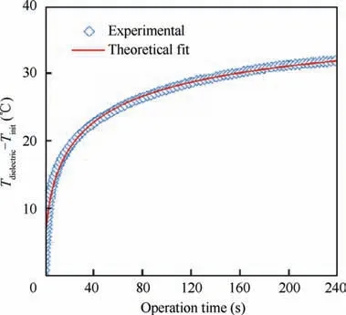
Fig. 7 Experimental results and theoretical data.87
The previous investigations indicated that most of the power consumed by the plasma actuator is used for gas heating83.However, compared with the study of dielectric heating, few studies of induced gas heating have been carried out because of the lack of relatively mature testing technology.The following part reviews the latest researches on gas heating produced by the plasma actuator from three research methods:cold wire experiments, spectroscopy emission measurements, and a designed experimental device.
2.2.1. Gas temperature measurement by using cold wire
Compared with the measurements of dielectric temperature,there have been a limited number of experimental studies on gas heating. Jukes et al.88studied the gas temperature using a Dantec 55P31 cold wire, which is relatively insensitive to flow. The uncertainty of this cold wire was 0.1 °C based on the calibration results.
It was found that the maximum difference in gas temperature caused by the DBD plasma actuator was 2 °C. Interestingly, the pattern of the temperature distribution is similar to that of the flow field, as shown in Figs. 8 and 988. Although the distribution of the instantaneous gas temperature can be obtained by using the cold wire, the distribution of the gas temperature close to the plasma actuator is still missing because the high electric field may destroy the cold wire.
2.2.2. Spectroscopy emission measurements for gas temperature
It is believed that the rotational temperature is approximately equal to the translational temperature and can be regarded as the gas temperature at atmospheric pressure because the rotational excitation energy is not prominent and the equilibrium state between the neutral molecules and the molecules of the rotational states is easy to achieve86.Based on this approximation,Stanfield89and Dong90et al.studied the gas temperature using spectroscopy emission measurements and the synthetic spectrum provided with SPECAIR.Here,a quartz optical fiber linked to a spectrometer Mechelle ME5000 (AndorTM)equipped with an ICCD camera was adopted to gather the light released from the plasma discharge directly. This spectrometer with high spectral resolution (λ/Δλ = 4000, λ is the plasma emission wavelength)can measure a spectrum of more than 600 nm based on the calibration results. The spectroscopic emission measurement presented in Fig. 1090indicated that the molecular bands of N2dominate the plasma light emission and its intensity is much higher than the molecular bands of N2+. In addition, the vibrational temperature is 3000 K and the rotational temperature, which is approximately identical to the average gas temperature, is 380 K.Although the spectroscopy emission measurement can be used to acquire the instantaneous gas temperature at a single coordinate point,the distribution of the gas temperature still needs to be studied.

Fig. 8 Instantaneous temperature contour around symmetrical plasma actuator.88

Fig. 9 Smoke flow visualization image around symmetrical plasma actuator.88

Fig. 10 Experimental and simulation spectra of N2 second positive.90
2.2.3. Designed experimental device for gas temperature
According to calorimetric principles, Rodrigues et al.83devised an experimental device for evaluating the thermal power consumption of the plasma actuator.The device is presented in Fig. 1183, which is made of a pipe with the length of 210 mm and the diameter of 43 mm and a fan (ME40101V1-000U-A99, with dimensions of 40 mm × 40 mm × 10 mm).In order to reduce heat dissipation from the pipe surface as much as possible, a thermal insulation layer made of highquality cork with an extremely low thermal conductivity(0.04 W/(m·K)) is used for covering the pipe. The fan, which is driven by a DC power, generates a constant flow with the speed of 2.6 m/s. The Reynolds number of the pipe flow is approximately 7400. Under turbulent conditions, the heat transfer becomes a relatively fast process.The plasma actuator was arranged inside the pipe,and a thermocouple was used to measure the gas temperature at the outlet.
Before calculating the thermal power consumption of the heating gas by using this method, a verification experiment was conducted to obtain the accuracy of the experimental measurement results. The results suggested that the relative error related to the measurements was less than 10%.
Based on the fundamental calorimetric law,the heat energy that shifts from one body to another during an isobaric process is calculated by
Q=mcpΔT (3)
where ΔT represents the temperature changes,m stands for the body mass, and cprepresents the specific heat capacity at constant pressure.
In this experiment, the energy created by the plasma actuator shifts to the gas in the pipe. Therefore, based on the fundamental calorimetric law, the heat energy transferred per second is similar to the thermal power consumed by the plasma actuator when the mass is replaced by the mass flow rate ( ˙m).Combining the density with air flow rate,the mass flow rate of air can be calculated( ˙m=ρairφ,ρairis the air density and φ is the air flow rate).Therefore,the thermal power is obtained by

Based on the difference between the total thermal power consumption acquired by Eq.(4)and the dielectric heating calculated by Eq. (1), the gas heating can be obtained, as shown in Fig. 12.83Here, the active power in Fig. 12 represents the total power consumption of the plasma actuator. The results indicated that 70%-85% of the total power consumption of the DBD plasma actuator is used for gas heating,and less than 10% of the total power consumption is converted into dielectric heating. It should be noted that the thermal power consumption is linked to the dielectric permittivity of the material, and dielectric heating is associated with the dissipation factor,tanδ,as shown in Eq.(1).The averaged gas heating from the perspective of power consumption can be obtained.However, the instantaneous thermal power consumption is still unknown.

Fig. 11 Air flow calorimeter for quantification of heat generated by DBD plasma actuators.83

Fig. 12 Total power consumption, total thermal power, and dielectric thermal power vs applied voltage.83
Although several aforementioned methods can be applied to investigate the gas heating created by the plasma actuator,the spatial and temporal distribution of the gas temperature in the vicinity of the plasma actuator,which is very important for understanding the formation and transfer of the induced heating, is still not very clear.
3. Influence of different parameters
Based on the understanding of the fundamental thermal characterization of the plasma actuator, the influence of different parameters, as shown in Fig. 13, on the thermal characterization is summarized in this section.
3.1. Thickness of dielectric film
Infrared images of the dielectric heating for different dielectric thicknesses from the top view at the same input voltage are presented in Fig. 14.90

Fig. 13 Different parameters affecting thermal characteristics.
Here, an FLIR i7 thermal camera with an uncertainty of 2% was adopted to measure the temperature of the dielectric surface immediately after the operation of the plasma actuator.Before the experiments, the plasma actuators were painted with a black ink with known emissivity to ensure the feasibility of the measurements. The location of the upper electrode is represented by a dashed square. Initially, the thickness of the dielectric film has a negligible influence on the dielectric temperature distribution. Then, the temperature of the dielectric film is increased by decreasing the thickness of the dielectric,as shown in Fig.15.86Here,ΔT is the variation of the dielectric temperature,and ΔTmaxdenotes the maximum variation of the dielectric temperature.
Fig. 16 shows the active power, total thermal power, and dielectric thermal power versus applied voltage for different thicknesses of the dielectric film83. Here, d is the thickness of the dielectric film and the active power in Fig. 16 represents the total power consumption of the plasma actuator, and the uncertainty of these results is less than 10%. The results indicate that the influence of the thickness of the dielectric film on the proportion of the dielectric thermal power to the total power consumption is obvious. Compared with other cases whose 75%-95% of the total power consumption is used for generating the heating, the proportion of the total thermal power to the total power consumption ranges from 45% to 70% when the thickness of the dielectric film is equal to 0.3 mm.Although the thinnest plasma actuator shows a lower percentage of total power converted in heat, it presents high values of thermal power transferred to the surrounding flow(for the same applied voltage).This agrees well with the results of Rodrigues et al.83, who suggested that the temperature levels are highest for thin dielectrics at the same applied voltage compared with other cases.This conclusion is of great significance to the selection of the thickness of the dielectric according to the research purpose. The plasma actuator of the thin dielectric film is suitable for anti-icing and deicing since the induced heating of the plasma actuator is higher than the one of the thick dielectric film.
3.2. Material of dielectric film
Fig. 1791presents the infrared images with an uncertainty of 2% for different materials of the dielectric film from the top view at the same input voltage. Similar to the influence of the thickness of the dielectric film on the dielectric temperature,as shown in Fig.14,the dielectric material mainly affects the magnitude of the dielectric film temperature, but has little influence on the distribution of the temperature of the dielectric film.
Fig.1883depicts the active power,total thermal power,and dielectric thermal power versus applied voltage for different materials of the dielectric film, and the uncertainty of these results is less than 10%.Here,the active power in Fig.18 represents the total power consumption of the plasma actuator.The results indicated that the material of the dielectric film can affect the proportion of the total thermal power to the total power consumption.Compared with the other two cases,the use of poly-isobutylene rubber as the dielectric film of the plasma actuator can reduce the proportion of the total thermal power to the total power consumption.

Fig. 14 Infrared images of dielectric temperature with different dielectric thicknesses.90

Fig. 15 Influence of dielectric thickness on variation of dielectric temperature.86

Fig. 16 Total power consumption (active power), total thermal power, and dielectric thermal power with different dielectric thicknesses.83
3.3. Shape of upper electrode
Previous studies indicated that the shape of the upper electrode can affect the discharge characteristics of the plasma actuator and the velocity of the wall jet generated by the plasma actuator92. However, the influence of the shape of the upper electrode on the thermal characteristics of the plasma actuator has not yet been studied in depth. Based on this background,Tirumala et al.carried out experiments on the thermal features of the plasma actuator using the rectangular-electrode-to-rec tangular-electrode and circular-electrode-to-rectangular-elec trode configurations, as shown in Fig. 19.86In both cases,the 3 mm thick dielectric film was adopted and the highvoltage sinusoidal frequency of 1000 Hz was used. The 80 μm thick rectangular electrode and the diameter of the circular electrode of 25 μm were utilized. The uncertainty of the wall temperature using infrared thermography camera is less than 0.4 K.

Fig. 17 Infrared images of dielectric temperature with different materials of dielectric film 91.

Fig.18 Total power consumption(active power),total thermal power,and dielectric thermal power with different materials of dielectric film.83

Fig. 19 Sketch of DBD plasma actuators.86
The maximum temperature variations of the dielectric film,ΔTmax, with voltage amplitudes for the rectangular-electrodeto-rectangular-electrode and circular-electrode-to-rectangularelectrode configurations are shown in Fig. 20.86Compared with the rectangular-electrode-to-rectangular-electrode configuration, the increase in temperature generated by the plasma actuator with the circular-electrode-to-rectangular-electrode configuration is higher at low voltages. However, the differences between the two cases are not obvious at higher voltages.At a given power consumption, ΔTmaxinduced by the plasma actuator with the circular-electrode-to-rectangular-electrode configuration is slightly lower than that in the rectangular-elec trode-to-rectangular-electrode configuration.
To further distinguish the difference in thermal characteristics between the rectangular-electrode-to-rectangular-electrode and circular-electrode-to-rectangular-electrode configurations,Fig. 2186shows the temperature distribution of the dielectric film in the case of a circular-electrode-to-rectangular-electrode configuration. It can be observed that compared with the case of the rectangular-electrode-to-rectangular-electrode configuration, as shown in Fig. 4, the distribution of the increase in temperature produced by the plasma actuator with the circular-electrode-to-rectangular-electrode configuration is more uniform.Moreover,the region of the relatively high temperature in the case of circular electrodes is narrower than that of the rectangular-electrode-to-rectangular-electrode configuration.
Fig. 2286depicts the temperature distributions along the streamwise and spanwise directions respectively in the case of the circular-electrode-to-rectangular-electrode configuration by extracting the data from the thermal image, as shown in Fig.21.It should be noted that the pattern of the temperature distributions along the streamwise and spanwise directions is similar to the case of rectangular-electrode-to-rectangular-elec trode configuration, as shown in Fig. 5. The rise in temperature along the streamwise direction rapidly decreases within 20 mm, and the decreasing tendency of temperature slows down beyond the region of 20 mm.For the spanwise direction,the noteworthy variation in the dielectric film temperature is concentrated within the span length of the upper electrode and decreases rapidly beyond the span length of the upper electrode.

Fig. 20 Maximum temperature variation of dielectric film (ΔTmax) at different voltage amplitudes and power consumptions.86

Fig. 21 Thermal images of DBD plasma actuators in case of circular-electrode-to-rectangular-electrode configuration.86
However,the location of ΔTmaxis different between the two configurations. The origin of the coordinate system was fixed at the junction between the upper electrode and the lower electrode. For rectangular-electrode-to-rectangular-electrode configuration, ΔTmaxis almost at x = 1 mm. For the circularelectrode-to-rectangular-electrode configuration, the maximum temperature variation is approximately at x = 0 mm.In addition,the temperature distribution in the spanwise direction is more uniform compared with that of the rectangularelectrode-to-rectangular-electrode configuration, as shown in Fig. 5.
To reveal the underlying mechanism of the differences in the thermal features of the plasma actuator between the rectangular-electrode-to-rectangular-electrode and circular-ele ctrode-to-rectangular-electrode configurations, Debien93and Tirumala86et al. studied the electrical characteristics for both cases. Fig. 2386presents the micro-discharge of the plasma actuator during the positive- and negative-going cycles for both cases.
For the plasma actuator with the rectangular-electrode-torectangular-electrode configuration,the micro-discharge in the positive-going cycle is dominated by the propagation of streamers that extend from the upper electrode up to approximately 20 mm. One extension from a bright spot zone is located at the junction of the upper electrode and the lower electrode towards the dielectric surface. These extensions are branched over a few filaments with stochastic propagation paths. In the negative-going cycle, diffuse micro-discharges that extend with a plume shape occur. Compared with the streamer discharge observed in the positive-going cycle, the diffuse micro-discharge is more uniform.
The distinct difference in the characteristics of the microdischarge between the rectangular-electrode-to-rectangular-el ectrode and circular-electrode-to-rectangular-electrode configurations occurs in the positive-going cycle. For the circular-el ectrode-to-rectangular-electrode configuration, there is no streamer in the positive-going cycle, and the diffuse microdischarge is similar to the case of the rectangular-electrode-t o-rectangular-electrode configuration in the negative-going cycle.More details on the micro-discharge of the two cases can be found in the recent references45,87,93.

Fig. 22 Temperature distribution for circular-electrode-to-rectangular-electrode configuration.86

Fig. 23 Images of discharges of DBD plasma actuators during positive- and negative-going cycles.86
In addition to micro-discharge, the characteristics of the current are another way to show the difference between the two cases. For the plasma actuator with the rectangular-elec trode-to-rectangular-electrode configuration, the pattern of the current can be divided into two parts by the positiveand negative-going cycle, as shown in Fig. 24(a)86. Because of the streamer discharge,the positive-going cycle is characterized by a few high current pulses94.The glow-like regime acting during the negative-going cycle leads to low current pulses.
For a circular-electrode-to-rectangular-electrode configuration, the high current pulses disappear in the positive-going cycle owing to the suppression of the streamer discharge by the circular electrode, as shown in Fig. 24(b). In the negative-going cycle, the difference in the current characteristics between the two cases is not significant.
Based on the previous discussion, the primary mechanism causing the differences between the two cases is whether there is a streamer discharge developing in the positive-going cycle.The streamer discharge can affect the current characteristics in the positive-going cycle and influence the pattern of the distribution of the dielectric temperature, as shown in Fig. 21. It can be observed that the high-temperature region of the rectangular-electrode-to-rectangular-electrode configuration is wider than that of the circular-electrode-to-rectangular-elec trode configuration. However, the influence of the streamer discharge on the maximum temperature of the dielectric film is negligible.In addition,these results suggest that the thermal characteristics, plasma discharge, and current characteristics are highly interrelated.
3.4. Voltage amplitude
The temperature variations of the dielectric film along the spanwise direction at different voltage amplitudes are shown in Fig. 25(a)91, and the uncertainty of the measured temperature of the dielectric film is 0.2%. Here, l is the length of the exposed electrode.Initially,the influence of the voltage amplitudes on the pattern of the distribution of the temperature variations is not very obvious. The temperature variations are concentrated in the region of the spanwise length of the plasma actuator, and the temperature decreases rapidly when the region is beyond the spanwise length of the plasma actuator. Second, the maximum temperature of the dielectric film increases with the voltage amplitude. Third, the fluctuations of the temperature variations are enhanced with the voltage amplitudes. It is believed that these fluctuations are related to the hot spots of the non-uniform plasma discharge, which indicates that the temperature variations of the dielectric film and the plasma discharge are highly correlated91.
Fig.25(b)91shows the temperature variations of the dielectric film along the streamwise direction at different voltage amplitudes. Here, w is the width of the exposed electrode.The maximum temperature of the dielectric film increases with the voltage amplitude,in a similar way to the temperature variations along the spanwise direction. However,the influence of the voltage amplitudes on the location of the maximum temperature is not very obvious.
3.5. Voltage waveform
As discussed above, the thermal characteristics of the plasma actuator and the plasma discharge are highly correlated. As indicated by Benard and Moreau92,the features of the plasma discharge regimes can be adjusted by the shape of the voltage waveform.Therefore,the thermal characteristics of the plasma actuator can be affected by the shape of the voltage waveform,which has been studied by Tirumala et al.86.Here,four different input waveforms,sinusoidal,square,positive,and negative ramps,were adopted.For all cases,the voltage was 36 kV and the frequency was 1000 Hz. The discharge was operated for 240 s.
The thermal images of the dielectric film, plasma discharge images,and corresponding current curves for all four cases are shown in Fig. 26.86The uncertainty of the wall temperature using infrared thermography camera is less than 0.4 K. It should be noted that the influence of the shape of the voltage waveforms on the pattern of the plasma discharge and the temperature distributions of the dielectric film is obvious, which confirms that the thermal characteristics of the plasma actuator and the plasma discharge are highly correlated.The region of the relatively high temperature in the case of the square waveform is much wider than that in other cases. In addition,the maximum temperature of the dielectric film in the case of the positive ramp waveform is higher than that in other cases.

Fig. 24 Current and voltage of DBD plasma actuators versus time.86

Fig. 25 Temperature variation of dielectric film along spanwise and streamwise directions at different voltage amplitudes.91
Fig.2786shows the relationship between the maximum temperature of the dielectric film and the power consumption of the plasma actuator under different voltage waveforms. It can be observed that the increase in temperature of the dielectric film is not completely proportional to the electrical power consumption.Compared with other cases,the temperature created by the plasma actuator with positive ramp waveform is maximum, but the power consumption for the positive ramp waveform is not the maximum.
3.6. High-voltage frequency
Recently, Tirumala et al.86studied the effect of the input frequency (fac) on the maximum temperature variation of the dielectric film (ΔTmax). Fig. 2886presents ΔTmaxversus facfor a dielectric film with a thickness of 3 mm. The uncertainty of the wall temperature using infrared thermography camera is less than 0.4 K. It can be observed that the relationship between ΔTmaxand facis linear.
3.7. Incoming flow
The plasma actuator usually operates under an incoming flow.To be close to reality, Rodrigues et al.91studied the influence of the incoming flow on the temperature of the dielectric film,and the uncertainty of the measured temperature of the dielectric film is 0.2%. Fig. 2991shows the thermal image of the dielectric film under the incoming flow. Comparing the temperature distribution of the dielectric film in quiescent air as shown in Fig.14(a),we can see that the maximum temperature is decreased owing to the heat transfer between the induced heating of the plasma actuator and the incoming flow. Meanwhile,the region of relatively high temperature is moved to the dielectric film,which agrees with the results of Tirumala et al.86,who suggested that the temperature distribution of the major part of the dielectric film is affected by the convection of gas above the plasma actuator.
Recently, Joussot et al.87distinguished the difference between the influence of laminar flow and the effect of turbulent flow on the temperature of the dielectric film,as shown in Fig. 30. It can be observed that the temperature of the dielectric film is minimum under turbulent flow. It is believed that the heat dissipation is usually higher in the turbulent layer than in the laminar boundary layer.

Fig. 26 Characteristics of the current (left), plasma discharge images (middle), and temperature variation of dielectric film (right) for different voltage waveforms.86
3.8. Summary
Based on the above discussion, the influences of the thickness and the material of the dielectric film, the shape of the upper electrode, the voltage amplitude, the voltage waveform, the high-voltage frequency, and the incoming flow on the induced heating of the plasma actuator have been summarized.In fact,all the parameters affect the micro-discharge regimes of the Fig.29 Maximum temperature variation of dielectric film under incoming flow.91plasma actuator.And the discharge process which is regulated by the ionization-recombination process can be predicted and simulated by using some numerical simulation methods.95Since the research progress of the thermal characteristics of the plasma actuator is summarized by reviewing the experimental investigations majorly in the present paper,the numerical simulation studies can be referred to in the recent publication.96

Fig. 27 Maximum temperature of dielectric film and power consumption of plasma actuator under different voltage waveforms.86
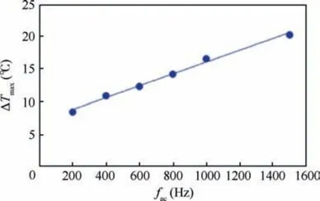
Fig. 28 Maximum temperature variation of dielectric film(ΔTmax) vs input frequency (fac).86

Fig.30 Maximum temperature of dielectric film in quiescent air,under laminar and turbulent flows.87
The plasma actuator has particular characteristics, including optical (plasma discharge), electric (current and voltage curves), and heat characteristics. More importantly, these characteristics are highly correlated30. According to the influence of the shape of the voltage waveform, the discharge regime can adjust the current of the plasma actuator and affect the thermal characteristics.Therefore,the thermal characteristics can be adjusted by changing the optical and electric characteristics.
Furthermore, most of the previous studies focused on the influences of different parameters on the temperature of the dielectric film of the plasma actuator. Few investigations have considered the influence of the raised temperature of the surrounding gas of the plasma actuator on the induced flow field created by the plasma actuator. Erfani et al. investigated the effect of the temperature of the dielectric film on the induced flow field and found that the velocity of the wall jet produced by the plasma actuator increased with the temperature of the dielectric film97.
4. Discussion
The present paper reviews the research progress of thermal characteristics from four aspects:basic thermal characteristics,the influence of the different parameters, the formation mechanism,and the heat transfer formation of the plasma actuator.Table 1 shows the overview of the main conclusion of the thermal characteristics of the plasma actuator. Initially, both dielectric heating and gas heating are the manifestations of heat transfer from the DBD plasma actuator to the surrounding objects, and more than two-thirds of the total power consumption of the plasma actuator is gas heating. Secondly,dielectric heating can be changed by adjusting the different parameters. In fact, the strength and the distribution of the electric field, the discharge regimes, and the speed of the heat convection have been changed when the different parameters are adjusted.Thirdly,the formation mechanism of heating will be discussed in Section 4.1 based on the two different dischargeregimes during the positive-and negative-going cycles.Finally,the mechanism of heat transfer will be analyzed in Section 4.2.

Table 1 Overview of experimental investigations on thermal characteristics of plasma actuator.
Although the previous investigations made great contributions to understand the thermal characteristics of the plasma actuator, there are still open issues that need to be studied in depth. Table 2 presents the existing problems and possible solutions. Here are three problems that require to be solved.Firstly, the instantaneous distribution of dielectric heating is not very clear. Due to the limited sampling frequency of the infrared thermal imaging camera, the instantaneous distribution of the dielectric heating is still blank. The reconstruction of the distribution of the dielectric heating based on the infrared thermography measurements and lock-phase technology might solve this issue. Secondly, it is difficult to capture the spatial and temporal distribution of the gas heating since the plasma discharge could damage the sensor by a high electric field. The reconstruction of the distribution of gas heating based on the spectroscopy emission measurements and a three-axis traverse mechanism might obtain the spatial and temporal distribution of gas heating. Thirdly, the formation mechanism of the heating needs to be studied further by carrying out simultaneous measurements of surface/gas temperature, plasma discharge, current characteristics, and induced flow field.

Table 2 Existing problems and possible solutions.
Firstly,revealing the formation mechanism of the heating is the first step for understanding the thermal characteristics.Secondly, the interaction between the induced flow field and the heating should be analyzed. Then, the numerical simulation of the induced heating is established based on the first two steps.Finally,the induced heating can be controlled by changing the parameters according to the research purpose. These suggested research directions open up the whole chain from fundamental research to engineering application.
4.1. Potential formation mechanism of heating
Although many previous studies have made significant efforts to enhance the potential industrial application of the plasma actuator and elucidate the influence of different parameters on its thermal characteristics, the formation mechanism of the induced heating is not very clear.In this section,the potential formation mechanism of heating is discussed based on recent investigations. According to the aforementioned summary, the plasma actuator has two discharge regimes, namely the streamer discharge that occurs in the positive-going cycle,and the glow discharge, which develops in the negative-going cycle. And the discharge regimes and the thermal characteristics of the DBD plasma actuators are correlative.Here,the discussion on the formation mechanism of heating is based on two types of discharge regimes.

Fig. 31 Relationship between temperature of dielectric film and light intensity of plasma discharge.86
4.1.1. Glow discharge regime
Tirumala et al.86believed that the glow discharge is the main mechanism of heating by making a comparison between the thermal image of dielectric film and a photograph of plasma discharge. Fig. 31(a)86shows the superimposed image of the plasma discharge and the corresponding thermal photograph,and the uncertainty of the wall temperature using infrared thermography camera is less than 0.4 K. The plasma actuator is driven by a sinusoidal waveform with a voltage amplitude of 36 kV and an input frequency of 1 kHz.It can be observed that the relatively high temperature regions are in good agreement with the glow discharge spots.Fig.31(b)86presents the temperature(T)and light intensity(Il)along the spanwise direction of the plasma actuator normalized to their respective minima and maxima,that is,Tnorm=(T-Tmin)/(Tmax-Tmin)and Ilnorm= (Il- Ilmin) / (Ilmax- Ilmin). A relatively good correlation between the temperature of the dielectric film and the light of the glow discharge can be observed. In addition, Tirumala et al.86found that the image of streamer discharge and the thermal photograph of dielectric film are uncorrelated. Based on these results, Tirumala et al.86suggested that the glow discharge that occurs in the negative-going cycle is the crucial engine for producing the heating.
However, the temperature image is a cumulative effect of 240 s, and the discharge photograph is instantaneous. Therefore, the aforementioned discussion is only a reasonable speculation, and the formation mechanism of heating is still not very clear.
4.1.2. Streamer discharge regime
Based on the above discussion, the major cause of the differences in the thermal images between the rectangular-elec trode-to-rectangular-electrode and circular-electrode-to-rectan gular-electrode configurations, as shown in Fig.26,is whether there is a streamer discharge developing in the positive-going cycle,which indicates that although the glow discharge regime plays an important role in generating the heating,the contribu-Fig.32 Schlieren visualization image of propagating acoustic waves taken 40 μs after initiation of plasma actuator.94tion of the streamer discharge to the heat formation of plasma actuator cannot be ignored86. In this section, the relationship between streamer discharge and induced heating is discussed.
Actually,the plasma actuator emits a distinct sound during operation98,99, which indicates that the plasma actuator may generate some acoustic waves, namely pressure waves. However, few researchers have investigated the characteristics of the induced pressure waves of the DBD plasma actuator.Recently, a series of acoustic waves propagating from the plasma actuator to the outside were observed by using a high-accuracy phase-lock image freezing schlieren technique,as shown in Fig. 32.94The overall uncertainty to capture the position of the acoustic wave produced by the plasma actuator was estimated to be about 3 pixels by the 10 times repeated experiments94.
It is evident that the high current pulses correlate strongly with the pressure measured by a pressure-field microphone(Bru¨el & Kjær type 4138-A-015) in the positive-going cycle,as presented in Fig.33.94Therefore,it is reasonable to assume that the induced pressure waves are related to the streamer discharge. It is speculated that a large number of current pulses created by the streamer discharge have high amplitudes and generate heat rapidly, leading to the fast variation of gas density and pressure around the plasma actuator45,86.Therefore,because of the high-frequency pressure oscillation,these acoustic waves, namely pressure waves, are produced.
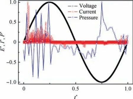
Fig. 33 Normalized voltage waveform E*, current I*, and pressure P* vs non-dimensional time.94

Fig. 34 Sketch of temporal variation of energy transfer process that occurs in an atmospheric-pressure streamer discharge.104
According to a few previous studies, the enhancement of translational energy, which is approximately equal to the gas temperature in an atmospheric pressure caused by the streamer discharge includes two steps, namely, the isochoric and isobaric processes100-103.Fig.34104presents a sketch of the energy transfer process that exists in a streamer discharge.
Initially, the isochoric process is referred to as the ‘‘rapid gas heating” process within a streamer discharge and is produced by the quenching process of electronically excited molecules, such as N2(C3∏u) and N2(B3∏g). The pressure is enhanced in the streamer discharge channel since the time of the releasing of pressure is decided by the velocity of sound and is more than the time of the quenching process of N2(C3∏u) and N2(B3∏g). Then the pressure wave is generated after the plasma discharge finished. This further elaborates the mechanism of generating the pressure waves, as shown in Fig. 32.
In addition,the isobaric process happens after the isochoric process and is created by the energy releasing of the vibrationally excited molecules. This process is called the slow gas heating process since the velocity of the sound is faster than the time of the vibrationally excited molecules. With the help of the slow gas heating process,under the condition of almost constant pressure, the translational temperature is improved after the pressure waves release.
Based on the aforementioned discussion, the contribution of the streamer discharge to the enhancement of gas temperature is complicated and cannot be ignored. Meanwhile, it should be noted that the discussion on the formation mechanism of heating is far from complete and can only serve as a starting point for further investigation.
4.2. Heat transfer mechanism
In addition, another important issue that needs to be further discussed is the induced heat transfer mechanism combined with the aerodynamics of the DBD plasma actuator. The previous studies postulated that the major heat transfer mechanism between the plasma actuator and the dielectric film is through convection. However, the effect of the direct heat injection of plasma actuator is not very obvious86. The significant evidence supporting this hypothesis is presented below.
Initially, in the case of the circular electrode as an upper electrode, the glow discharge is centralized along the junction between the upper electrode and the lower one, with an extension of approximately several millimeters, as shown in Fig. 23(b). The previous study indicated that this area of glow discharge is the only region where the heat energy transfers from the plasma to the dielectric film directly86.The dielectric film made of acrylic materials blocks the heat transfer downstream of the plasma actuator rapidly due to its extremely low thermal conductivity (0.2 W/(m·K)). However, the region of the raised temperature distribution, as shown in Fig. 21, is wider than the area of the plasma discharge. Therefore, it can be hypothesized that convection plays an important role in heat transfer.
Moreover, the raised temperature of the dielectric film is mainly focused on the region of the junction between the two electrodes,with a fast decrease to the sides along the spanwise(y)direction,as shown in Fig.5(b).This is in line with the induced wall jet above the dielectric film, which is created within the area of plasma discharge.
These results suggested that the temperature distribution of dielectric film is determined by the induced wall jet majorly above the dielectric film through convection, and the internal conduction of the induced heating plays a minor role in heat transfer between the plasma and the dielectric film.
In the rectangular-electrode-to-rectangular-electrode configuration (Fig. 5(b)),the intense temperature disturbance created by plasma actuator along the spanwise direction in the vicinity of the junction between the upper electrode and the lower one (x = 1 mm) and the more uniform perturbation at a downstream position (x = 6 mm), also agrees with the assumption. The temperature disturbances are formed due to direct internal injection of heat at the non-uniform glow discharge positions (Fig. 23(a)). Then the temperature distribution downstream of the upper electrode becomes more uniform due to the convection of heat transfer from the discharge spots to the downstream area.Because the downstream heat transfer is dominated by convection from hot gases, it becomes more uniform.
4.3. Future perspective
The research field of flow control using the DBD plasma actuator has witnessed an explosive growth recently because of the enhancement of the understanding of the aerodynamics of plasma actuator and its significant potential to improve dramatically the aerodynamics performance of aeronautical airplanes and ground vehicles by using its induced flow field. However, the maximum electromechanical efficiency of plasma actuator (the ratio of the energy consumed by the actuator to produce the induced flow field to the total energy consumed by the actuator) is no more than 0.2%45, and most of the total energy is used in gas heating and dielectric heating, which indicates that most of the total energy consumed by the actuator has not been fully utilized.
This paper lays a foundation for understanding the formation and transfer mechanism of the induced heating of the plasma actuator and motivates researchers to pay more attention to the thermal characteristics of plasma actuator by reviewing the recent developments in this area.
In 1857,Ernst Werner von Siemens found that a novel type of gas discharge,the DBD,can generate ozone at atmospheric pressure. After that, DBD rapidly became the mainstream ozone generation industry, and the ozone generator based on DBD plasma has reached market volumes that correspond to at least 10 times the original ozone market. Over a century and a half later, it is clearly possible to promote the potential capability and extend the application region of the DBD plasma actuator if we could determine the formation and transfer mechanism of the induced heating and take advantage of this induced heating.
5. Conclusions
The present paper reviews the research progress of thermal characteristics from four aspects:basic thermal characteristics,the influence of different parameters, the formation mechanism, and the heat transfer formation of plasma actuator. It is found that gas heating accounts for a large proportion of the total power consumption of plasma actuator compared with dielectric heating. Meanwhile, the influences of different parameters on dielectric heating have been summarized. It is believed that the strength and the distribution of electric field,the discharge regimes, and the speed of heat convection have been changed when different parameters are adjusted.In addition, based on the two different discharge regimes during the positive- and negative-going cycles, the formation mechanism of the heating has been discussed and it is found that there are two steps, namely rapid gas heating and slow gas heating during the streamer discharge. Finally, it is believed that convection is the main mechanism of heat transfer.
Although the recent developments in the thermal characteristics of DBD plasma actuators have been reviewed, there are some open issues that need to be further investigated.First,the formation mechanism of the heating created by the plasma actuator is still not very clear.At present,it is difficult to draw a conclusion about which type of discharge regime (streamer discharge and glow discharge) contributes significantly to the induced heat generation because the distribution of the gas temperature close to the surface is still a missing part.In addition, most of the studies on the influence of different parameters on the thermal characterization are based on the surface temperature of dielectric film, and the influence of different parameters on the gas temperature is rarely studied.However,it has been demonstrated that most of the power consumed by plasma actuator is used in gas heating.
In further investigations, one will carry out simultaneous measurements of surface/gas temperature, plasma discharge,current characteristics, and induced flow field to understand the relationship among different characteristics of plasma actuator, and reveal the formation mechanism of the induced heating.
Declaration of Competing Interest
The authors declare that they have no known competing financial interests or personal relationships that could have appeared to influence the work reported in this paper.
Acknowledgements
The authors gratefully acknowledge the support by the National Natural Science Foundation of China (No. 11902336), State Key Laboratory of Aerodynamics Foundation of China(Nos.SKLA2019020201 and JBKYC190103),CARDC Fundamental and Frontier Technology Research Fund, China (No.PJD20180144)and China Scholarship Council.
杂志排行

CHINESE JOURNAL OF AERONAUTICS的其它文章
- A review of bird-like flapping wing with high aspect ratio
- Rotating machinery fault detection and diagnosis based on deep domain adaptation: A survey
- Stall flutter prediction based on multi-layer GRU neural network
- Supervised learning with probability interpretation in airfoil transition judgment
- Effects of input method and display mode of situation map on early warning aircraft reconnaissance task performance with different information complexities
- Enhancement on parallel unstructured overset grid method for complex aerospace engineering applications