Primary Mg2Si phase and Mg2Si/α-Mg interface modifie by Sn and Sb elements in a Mg-5Sn-2Si-1.5Al-1Zn-0.8Sb alloy
2022-12-30WenpengYngYingWngHongboCuiGungxinFnXuefengGuo
Wenpeng Yng,Ying Wng,Hongbo Cui,b,Gungxin Fn,b,Xuefeng Guo,b
a School of Materials Science and Engineering,Henan Polytechnic University,Jiaozuo,Henan 454000,PR China
b Henan International Joint Research Laboratory for High-Performance Light Metallic Materials and Numerical Simulations,Henan Polytechnic University,Jiaozuo,Henan 454000,PR China
Abstract The microstructure of primary Mg2Si and the interface of Mg2Si/α-Mg modifie by Sn and Sb elements in an as-cast Mg-5Sn-2Si-1.5Al-1Zn-0.8Sb (wt.%) alloy were investigated.In the primary Mg2Si phase not only the Si atoms but also the Mg atoms could be substituted by Sn and Sb atoms,resulting in the slightly reduced lattice constant a of 0.627 nm.An OR of Mg2Si phase and α-Mg in the form ofwas discovered.Between primary Mg2Si phase and α-Mg matrix two transitional nano-particle layers were formed.In the rim region of primary Mg2Si particle,Mg2Sn precipitates sizing from 5 nm to 50 nm were observed.Adjacent to the boundary of primary Mg2Si particle,luxuriant columnar crystals of primary Mg2Sn phase with width of about 25 nm and length of about 100 nm were distributed on the α-Mg matrix.The lattice constant of the Mg2Sn precipitate in primary Mg2Si particle was about 0.756 nm.Three ORs between Mg2Sn and Mg2Si were found,in which the Mg2Sn precipitates had strong bonding interfaces with Mg2Si phase.Three new minor ORs between Mg2Sn phase and α-Mg were found.The lattice constant of primary Mg2Sn phase was enlarged to 0.813 nm owing to the solution of Sn and Sb atoms.Primary Mg2Sn had edge-to-edge interfaces with α-Mg.Therefore,the primary Mg2Si particle and α-Mg were united and the interfacial adhesion was improved by the two nano-particles layers of Mg2Sn phase.
Keywords: Mg2Si;Mg2Sn;Modification Interface;HRTEM.
1.Introduction
Mg alloys are widely applied in automotive,aeronautic and astronautic industries owing to their high specifi strength and stiffness,damping capacity,thermal conductivity and dimensional stability [1,2].Recently,Si-containing Mg alloys have received particular attentions due to the formation of thermally stable intermetallic compound of Mg2Si phase that has a low density of 1.99×10³kgm−3,a high melting temperature of 1085◦C,a high hardness of 4.5×10⁹Nm−2,a low thermal expansion coefficien of 7.5×10⁻⁶K−1and a high elastic modulus of 120 GPa [3,4].The Mg2Si phase is exceptionally stable and therefore could effectively impede grain boundary sliding at elevated temperatures,improve the mechanical properties and reduce creep rates [5–7].Mg-Si alloys prepared by ordinary ingot metallurgy process have very low ductility and strength resulting from the coarse primary Mg2Si particle and brittle eutectic phase [8–10].It is facile to break the eutectic rod-like Mg2Si phase and to produce alloys with fin Mg2Si particles uniformly dispersed in matrix for hypoeutectic Mg-Si alloys by employing hot working techniques such as hot extrusion [11] and severe plastic deformation [12,13].Nevertheless,hot working is powerless to refin primary Mg2Si phase [12].Moreover,hot working is easy to cause internal crack in primary Mg2Si particle,which is a latent risk to lead the premature failure of materials and results in low ductility and strength.
Therefore,it is essential to change the morphology and size of Mg2Si via suppressing the growth of Mg2Si phase by introducing alloying addition and/or external high-intensity physical energy filed such as ultrasonic [4] and electromagnetic vibration [14,15].Compared with physical method,modifica tion treatment is a more economical processing technique and available for generally commercial application.Furthermore,the alloying elements have the possibilities to improve the ductility of Mg2Si by solid solution and enhance the interface adhesion of Mg2Si/α-Mg.The modificatio effects of Mg2Si phase by adding various additions including K2TiF6[16],KBF4[16,17],Y [18],Y2O3[19],B [20],Sr [10,21–23],Sb [21,24,25],Ba [25,26],Ca [27,28],Bi [29],Nd [30],Gd [5,31],P [32],Yb [33],Na3PO4[33] have been investigated and two major modificatio mechanisms are proposed:(1) the addition give rise to the preferential formation of high melting point particles that could acted as the heterogenous nucleation substrates for the primary Mg2Si particles at initial stage of solidification Thus,the size of primary Mg2Si phase is refine by means of increase in quantity of primary Mg2Si particles;(2) the additional element can change the solidificatio condition of the primary Mg2Si because modifi cation atoms are preferentially absorbed into the solid-liquid interface during crystal growth,which can change the surface energy and suppress the anisotropic growth rate of the primary Mg2Si.Among the above additions,the modificatio elements with outstanding modificatio effect,such as Sb and Sr et al.,are considered having a combination function of above-mentioned modificatio mechanisms.
Generally,the primary Mg2Si phase and α-Mg exhibit nonadhesive interface,which were also frequently observed even in modifie alloys [29,34].Under stress conditions,cracks nucleate preferentially within primary Mg2Si particles or at Mg2Si/α-Mg interface,and easily propagate along Mg2Si/α-Mg interface.Therefore,in addition to the morphology and size of primary Mg2Si phase,the interface structure of Mg2Si/α-Mg is a crucial factor to the mechanical properties.In previous reports,the mechanism of modificatio was concluded based on the observation of the morphology evolution of primary Mg2Si particles.The investigations of primary Mg2Si particles focus on the cross section via metallographic examination [18,33] and/or three-dimensional features via using solvent extraction by employing scanning electron microscopy (SEM) and energy dispersive X-ray (EDX)spectroscopy [24,35].The detailed characterization of crystal structure of primary Mg2Si phase and the interface between Mg2Si particle and α-Mg,however,are absent as yet,which could be the direct evidences to reveal the essence of the effect of modificatio elements on Mg2Si phase.
Our previous report found that with Sn addition Mg2Si phase is converted into Mg2(SixSn1−x)phase that have greater ductility than that of pure Mg2Si phase [36].Combined additions of Sn and Sb show good modificatio effect on primary Mg2Si particle.Based on previous researches,a new wrought Mg alloy with composition of Mg-5Sn-2Si-1.5Al-1Zn-0.8Sb (at wt.%) is designed expecting to achieve high strength and ductility both at room temperature and elevated temperatures.In present paper we clarify the microstructure of primary Mg2Si and microstructural evolution between primary Mg2Si and α-Mg modifie by Sn and Sb elements using high-resolution transmission electron microscopy (HRTEM).The orientation relationships (ORs) and interfacial structures of Mg2Si/α,Mg2Sn/α and Mg2Sn/Mg2Si are discussed.
2.Experimental
The Mg-5Sn-2Si-1.5Al-1Zn-0.8Sb alloy was prepared by melting commercial pure Mg ingots (99.7%),Sn (99.9%),Al(99.8%),Sb (99.9%),and Mg-10wt.%Si master alloy in an electric resistance furnace at 750◦C under Ar + SF6atmosphere.The melt was hand-stirred 4 times with mean time interval of 10min in order to provide a homogeneous composition.The ingot with diameter of 50 mm was obtained by pouring melt into metal mould.Metallographic specimen was cut from the middle position and ground through 2000 grit SiC paper,and then polished to mirror with 0.5 μm alumina suspension and finall etched using a Nital etchant of 5%HNO3and 95% ethyl alcohol.The specimen was examined using a Merlin Compact file emission SEM equipped with an Oxford Instruments EDX spectrometer.TEM specimen was prepared from 1.0 mm thick plates cut with a slow-speed saw using diamond blade.Discs with 3 mm in diameter were punched out from the plate,and then mechanically ground to about 60 μm and twin-jet electro-polished to perforation in a mixture of 15vol.% nitric acid and 85vol.% methanol at−30◦C.Before TEM observation,the foils were ion-milled using a Fischoine model 1010 to remove the surfacial oxide fil at an accelerating voltage of 4.5 keV.TEM and HRTEM observations were carried out in a JEM-2100 microscope operating at 200 keV.
3.Results
Typical microstructural morphology of primary Mg2Si phase modifie by Sn and Sb elements is shown in Fig.1a.Polygonal Mg2Si particles with gray contrast were surrounded by white contrast compound with a maximal thickness of about 2.0 μm.It is noted that there was an interlayer with a thickness of about 0.5 μm as indicated by arrows between the primary Mg2Si phase and the white compound.The contrast of the interlayer was slightly darker than that of the peripheral compound.A few pits distributed on the interlayer was attributed to the etched result of nitric acid solution during sample preparation.
The composition of the primary Mg2Si particle,interlayer and peripheral compound were examined by calculating the average value of three EDX spectra.The representative EDX spectra are shown in Fig.1b.The EDX spectrum of Mg2Si particle showed prominent Mg Kα1,2peak,strong Si Kα1,2peak and weak Sn Lα1,2,Lβ1.The composition was Mg-32.4%Si-2.1%Sn-0.8%Sb (at.%).In the EDX spectrum of interlayer besides the prominent Mg Kα1,2peak and secondary Si Kα1,2peak,the Sn peaks were visibly enhanced.The Sb Lα1,2peak overlapped with Sn Lβ1peak and indistinct Sb Lβ2peak overlapped with Sn Lγ1peak.The composition of the interlayer was Mg-20.3%Si-8.7%Sn-5.6%Sb (at.%).The EDX spectrum of peripheral compound displayed prominent Mg Kα1,2peak,strong Sn Lα1,2peak and weak Si Kα1,2peak.The overlapped Sn Lβ1and Sb Lα1,2peaks were stronger than that of the interlayer.In addition,a clearly visible Sb Lβ1peak near Sn Lβ2peak was detected,as shown in the locally magnifie diagram (the inset).The composition was Mg-6.1%Si-24.5Sn%-6.2%Sb (at.%).It is noted that alloying element Al and Zn had no effect on primary Mg2Si phase and Mg2Si/α-Mg interface because no peaks of them were found in above regions.
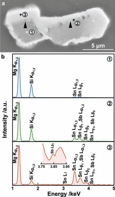
Fig.1.(a) SEM micrograph of primary Mg2Si phase and (b) representative EDX spectra recorded from primary Mg2Si particle,interlayer and surrounding intermetallic compound.
Fig.2a shows a typical TEM micrograph of the corner of a primary Mg2Si particle.The boundary of the particle was indicated by the white dashed line.The particle could be divided into two regions,the central area surrounded by the black dashed line,marked as “region A”,was clean and free of particles(a few irregular curves were regarded as bend contours).The rim area of the primary Mg2Si particle between the black and the white dashed lines,marked as “region B”,was fille with unequal-sized nanoparticles.
Fig.2b shows an HRTEM image recorded from region A with electron beam (EB) paralleled to [001] zone axis of Mg2Si phase,and the corresponding selected area electron diffraction pattern (DP) is shown in Fig.2c.In HRTEM image,since atomic potential of heavy element was larger than that of light element in electron beam direction,the site of atomic column of heavy element showed weaker intensity.Therefore,in Fig.2b the white and gray columns were recognized to be Mg atoms and Si atoms,respectively.A typical unit cell of Mg2Si phase was marked by a square,and the corresponding atomic sites are illustrated schematically in Fig.2d.However,some columns of Mg atoms showed gray contrast,and some columns of Si atoms showed dark contrast,typical ones were indicated by arrows 1 and 2,respectively.It means that the dissolved Sn and Sb atoms not only substituted Si atoms but also Mg atoms.However,as seen in the DP (Fig.2c),the {200} planes had weak reflection and the {220} planes had strong reflection it was a typical DP of superlattice structure.Therefore,it is reasonable to deduced that from the overall view the Mg2Si phase still retained the anti-fluorit structure.The measured value of crystal constantawas 0.627 nm.
The HRTEM micrograph of the small rectangle region in Fig.2a,which was a transition region between region A and B,is shown in Fig.2e.It is obvious that there was no obvious element segregation in region A.However,for the area in region B close to region A,obvious element segregation was observed,as indicated by the arrows.The Sn and Sb atoms prefer to substitute Si atoms.Its lattice constantawas the same as that of region A.
The concentration segregation of modificatio elements increased with the increase of distance from the black dashed line.Fig.3a shows a high magnificatio microstructure of the circle region in Fig.2a.There were many particles having size from 5 nm to 50 nm with dark contrast distributed on the Mg2Si matrix.Fresnel fringes with white contrast around some particles implied a significan difference in thickness existed between nanoparticles and Mg2Si matrix,as indicated by the black arrows.Moreover,a few particles showed Moiré fringes,as indicated by the white arrows,suggesting that the secondary phase and Mg2Si phase had a pair parallel (or with a small misorientation) crystal planes with approximate interplanar spacing.The corresponding DP (Fig.3b) of the circle region in Fig.2a was composed of single crystalline diffraction spots of[001]zone axis of the Mg2Si phase and speckled ringlike pattern on account of polycrystalline diffraction.The diffraction rings could be indexed to be Mg2Sn phase,and the calculated lattice parameterawas about 0.756 nm.
A representative area indicated by the rectangle in Fig.3a,which included Mg2Si matrix,particles with dark contrast and Moiré fringes,was investigated by HRTEM (Fig.3c).The FFT spectra of region 1 (Fig.3d) and region 2 (Fig.3e)in the HRTEM image (Fig.3c) were the same.The spectra could be indexed to be Mg2Si phase,the measured crystal plane spacing of (220) plane was 0.223 nm,and the calculated lattice constantawas almost the same as that of region A in Fig.2a.The central Mg2Sn particle(marked C1)showed Moiré fringes with a spacing of about 1.566 nm,corresponding to the superposition of the lattices of both the Mg2Si and Mg2Sn phase.In the FFT image (Fig.3f) of region 3(Fig.3c),besides the reflection of Mg2Si and Mg2Sn phase,extra reflection resulted from double diffraction were showed up deservedly,the corresponding analytical result is illustrated schematically in Fig.3g.The double diffraction occurred because the diffracted beam of Mg2Si phase was re-diffracted when it passed into the Mg2Sn phase,i.e.the thin slice of Mg2Sn crystal was beneath the slice of Mg2Si crystal.Obviously,the OR of Mg2Sn phase and Mg2Si matrix was in the form of [001]Mg2Sn‖[001]Mg2Si,(100)Mg2Sn‖(100)Mg2Si(OR1).According to the index,the (220) crystal plane could be determined at the rim of the Mg2Sn particle,and the spacing of which was measured to be 0.267 nm as indicated.With the lattice parameter of Mg2Si phase calculated above,the calculated spacing of the translational Moiré fringe was about 1.346 nm,which was consistent with that of experimental observations.Therefore,the translational Moiré fringe in Fig.3c corresponded to the superposition of the (220) planes of Mg2Sn and Mg2Si phase.

Fig.2.(a) TEM micrograph showing a corner of a primary Mg2Si particle;(b) HRTEM image showing the two-dimensional lattice structure of central region of the Mg2Si phase,arrows 1 and 2 indicate Mg and Si atomic columns,respectively;(c) DP recorded from region A in Fig.(a) with EB paralleled to [001]zone axis;(d) illustration showing the Mg and Si atomic sites in the unit cell of the Mg2Si phase which was labeled by the square in Fig.(b);HRTEM image of the small rectangle region in Fig.(a).
In addition to the central Mg2Sn particle marked C1,three small Mg2Sn particles with different crystallographic orientations marked C2,C3 and C4,respectively,were also observed.C2 particle had the same crystallographic orientation as C1 particle,however,no Moiré fringe on which was found.It could be ascribed to the thickness effect.C3 particle was overlapped partially with C2 particle.The orientation relationship of C3 particle and Mg2Si matrix was in the form of [111]Mg2Sn‖[001]Mg2Si,(22)Mg2Sn‖(220)Mg2Si(OR2).The OR of C4 particle and Mg2Si matrix could be described as [013]Mg2Sn‖[001]Mg2Si,(13)Mg2Sn‖(220)Mg2Si(OR3).It is noted that the measured crystal plane spacing of(131)Mg2Snwas 0.228 nm,which almost equaled to that of(220)Mg2Si(d(220)=0.223nm).Thus,it can be found that C4 particle had a distinct coherent interface with Mg2Si matrix and no lattice strain or distortion was observed along the interface.
According to the above analyses,it is found that Mg2Si matrix showed both bright and dark contrast,C2 and C3 Mg2Sn particles showed bright contrast.Hence,there was no corresponding relation between contrast and secondary phase particles.The particle-like contrast in Fig.3a was attributed to mass-thickness contrast.The non-uniform thickness was probably resulted from the sample preparation process of electropolishing.In fact,the sizes of Mg2Sn precipitates examined by HRTEM were from 5 nm to 30 nm.
The high magnificatio image of the large rectangle region in Fig.2a is shown in Fig.4a.The DP (the inset) in Fig.4a taken from the left clean region from the dashed line could be indexed to beα-Mg with the electron beam (EB)paralleled to [011] zone axis.The calculated lattice constants were a=0.321 nm and c=0.523 nm.Comparing with the DP in Fig.3b tilt operation was not carried out.Hence,the OR of primary Mg2Si phase and α-Mg was in the form ofThere was an inconspicuous phase boundary between primary Mg2Si particle and α-Mg,as indicated by the white dashed line in Fig.4a.Adjacent to the phase boundary there were luxuriant columnar crystals with width of about 25 nm and length of about 100 nm distributed on the α-Mg matrix,the longitudinal direction of which was approximately perpendicular to the white dashed line.It is implied that the columnar crystals were nucleated at the boundary of the primary Mg2Si crystal,and grew perpendicularly to the boundary of Mg2Si crystal during solidificatio process.Two kinds of typical columnar crystals at high magnificatio are shown in Fig.4b and c,respectively.The columnar crystals had irregular contour,especially,the tail sections of which were discontinuous.
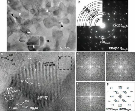
Fig.3.(a) High magnificatio TEM microstructure of region B in Fig.2a;(b) DP recorded from the circle region in Fig.2a;(c) HRTEM micrograph of the rectangle region in Fig.(a);(d–f) corresponding FFT images of regions d,e and f in Fig.(c),respectively;(g) schematic illustration of FFT image of region f,open circles were double-diffraction spots.
The HRTEM image of the rectangle region in Fig.4b is shown in Fig.5a.From the corresponding FFT spectrum(Fig.5b),besides the reflectio spots of α-Mg,strong reflectio spots of Mg2Sn-C1 and weak reflectio spots of Mg2Sn-C2 crystal with different crystallographic orientations were found.Moreover,double diffracted spots between α-Mg/Mg2Sn-C1 and Mg2Sn-C2/Mg2Sn-C1 were also presented.Fig.5c schematically illustrates the derivations of all diffraction spots in Fig.5b,the corresponding re-diffracted electron beams (RDEBs) and crystal of double diffraction of the spots (marked by Arabic numerals) are also pointed out.According to the FFT spectrum of the Mg2Sn phase,the calculated lattice constantawas about 0.813 nm.The enlarged lattice constant was ascribed to the solid solution of Sb element.However,on the basis of measured interplanar spacing of(02)plane,as denoted in the HRTEM image,calculated lattice constant of the dark contrast region(a=0.820 nm) was slightly larger than that of the gray contrast region (a=0.796 nm).Therefore,the dark contrast of the Mg2Sn phase and the difference in lattice constant were attributed to mass contrast due to different concentrations of the solid solution of Sb element.Owing to the almost equal interplanar spacing of(131¯)Mg2Snand(101)α,a coherent interface was observed between Mg2Sn phase and α-Mg,and their OR was clearly described as(OR1).The two-dimensional lattice of Mg2Sn-C2 crystal was difficul to be distinguished from HRTEM image due to the strong lattice contrast of Mg2Sn-C1 crystal.Whereas its crystallographic orientation and lattice constant could be confirme according to the FFT image.The OR of Mg2Sn-C2 crystal and α-Mg was define asWhile the OR of Mg2Sn-C2 and Mg2Sn-C1 was [001]C2‖[013]C1,(20)C2‖(3)C1.It is noted that the interplanar spacing of(20)C2was close to that of(3)C1.The calculated lattice constantaof Mg2Sn-C2 was 0.679 nm.

Fig.4.(a) High magnificatio image of the large rectangle region in Fig.2a and the inset showing DP recorded from α-Mg;(b) and (c) showing two typical microstructures of intermetallic compound adjacent to primary Mg2Si particle.

Fig.5.(a) HRTEM image of the rectangle region in Fig.4b.(b) Corresponding FFT image of (a).(c) Schematic illustration of the FFT image,the circled Arabic numerals indicate the spots of double diffracted crystals and corresponding RDEBs.

Fig.6.(a) HRTEM image of the rectangle region in Fig.4c.(b) The corresponding FFT image of (a).(c) Schematic illustration of the FFT image,the circled Arabic numerals indicate the spots of double diffracted crystals and corresponding RDEBs.
Fig.6a shows the HRTEM image of the rectangle region in Fig.4c,the analysis result of corresponding FFT image(Fig.6b) is schematically illustrated in Fig.6c.It is clear from Fig.6c that in Fig.6b besides the strong reflectio spots of α-Mg matrix,three sets reflectio spots of Mg2Sn crystals (marked C1,C2 and Mg2Sn(P),respectively,where P represented precipitate) with different crystallographic orientations were found.Likewise,double-diffraction between Mg2Sn-C1/α-Mg,Mg2Sn-C1/Mg2Sn-C2 and Mg2SnP/α-Mg occurred,the corresponding RDEBs and re-diffracted crystals of the double diffraction spots (marked by Arabic number in Fig.6c) are also indicated.In HRTEM image Mg2Sn-C1 crystal showed dark contrast and its reflectio spots in FFT image was strong.The calculated lattice parameterawas 0.813 nm.The OR between Mg2Sn-C1 and α-Mg was that(OR3).Moreover,the crystal interplanar spacing ofwas nearly equal to that ofwhich implied Mg2Sn-C1 crystal and α-Mg had a coherent interface.At the left boundary region of Mg2Sn-C1,as indicated by the black arrows,the contrast was brighter than that of the central region due to the reduction in thickness.In addition,evident rotational Moiré fringes with width of 0.612 nm was observed as a result of the overlap of Mg2Sn-C1 and α-Mg,which could correspond to the superposition of theplane andplane.Fig.6c implies thin slice of Mg2Sn-C1 crystal was on the top of slice of α-Mg crystal.The upper part of Mg2Sn-C1 crystal was superposed regions of Mg2Sn-C1 and Mg2Sn-C2 precipitates,as indicated,at where slight Moiré fringe with width of about 0.850 nm was observed.FFT spectra suggested Mg2Sn-C2 crystal was beneath the Mg2Sn-C1 crystal and the Moiré fringes were resulted from the planes of(31)C1and(200)C2.The calculated lattice constant of Mg2Sn-C2 was the same as that of Mg2Sn-C2 in Fig.5.Similarly,parallel planes of(220)C2and(13)C1with almost equal interplanar spacing also were found.The OR of Mg2Sn-C1 and Mg2Sn-C2 was described as [001]C2‖[114]C1,(220)C2‖(31)C1.The OR of Mg2Sn-C2 andα-Mg was OR2.Mg2Sn(P)was precipitate distributed on α-Mg matrix,as indicated.Although its twodimensional lattice was hard to be discriminated from the HRTEM image due to the strong contrast of matrix,slight Moiré fringes with width of about 1.46 nm was presented both at high magnificatio (Fig.4c) TEM micrograph and HRTEM image (Fig.6a).According to the FFT spectrum,the calculated interplanar spacing of the corresponding reflectio spots was 0.204 nm,which possibly belonged to {311}Mg2Sn.The corresponding g-vectors of Moiré fringes were(10)for α-Mg and the one indicated by an arrow for Mg2Sn(P).
4.Discussions
4.1.Solidificatio process
The combined additions of Sn and Sb showed good modificatio effect on the morphology of primary Mg2Si phase(Fig.1).According to previous reports in Mg-Si alloys modifie with Sb element,it is suggested that Mg3Sb2phase(space group(pm1),a=b=0.4573 nm and c=0.7229 nm)is formed prior to Mg2Si phase,which could act as the heterogenous nucleation site for nucleation of the primary Mg2Si crystal [25,37].A potential OR of(111)Mg2Si‖(0001)Mg3Sb2is proposed by calculating the disregistry (4.26%) of twodimensional lattices[35].In present study,however,there was no heterogenous nucleation particle observed in the central regions of primary Mg2Si particles (Fig.1) and the contents of Sn and Sb in interlayer were higher than that in the primary Mg2Si particle.Herein,at least one of the major effect of Sb and Sn elements was to restrain the growth of primary Mg2Si phase.
The solid solubility of Sn and Sb in Mg2Si are 2.1 at.%and 0.8 at.% (Fig.1b),respectively.It is report that Si site could be replaced by Sn and Sb atoms in Mg2Si crystal that results in the decrease of interface energies [35].Fig.2b shows that Sn and Sb preferentially replaced Si site,and the Mg site could also be replaced on the {400} crystal planes.Since Sn and Sb atoms were incorporated into primary Mg2Si phase by substituting Si and Mg sites,the interfacial energy of {100}plane was reduced markedly.Therefore,the growth direction of [001] was restrained,resulting in the primary Mg2Si crystal growing to a polygon morphology.Because of the limited solid solubility of Sn and Sb in Mg2Si phase,the redundant Sb and Sn atoms were enriched in the front of solid-liquid interface of growing primary Mg2Si crystal,which could restrict the growth of Mg2Si during solidificatio process.The DP (Fig.3b) of region B in Fig.2a showed the single crystal diffraction pattern of Mg2Si phase from [001] zone axis and polycrystalline rings of Mg2Sn phase,which implied that the nanoscaled Mg2Sn particles (Fig.3a) were distributed on the Mg2Si matrix.Therefore,it can be deduced that during the growth of Mg2Si crystal,the concentration of Sn and Sb in the front of solid-liquid was increased continuously,at fina stage of solidification partial Sn and Sb atoms were trapped in the primary Mg2Si crystal,formed a supersaturated solid solution,and the overabundance of Sn and Sb atoms were expelled from Mg2Si crystal.As the temperature decreased,the supersaturated Mg2Si phase decomposed and the Mg2Sn phase was more likely to precipitate.This deduction was consistent with the EDX spectrum result(Fig.1b)and the pseudo-binary phase diagram of Mg2Si–Mg2Sn [38].
Jung et al.reported that the peritectic reaction occurs after the formation of primary Mg2Si phase [38].The SEM microstructure in Fig.1a was similar to the peritectic microstructure in Mg-Sn-Si alloys,which is generated by peritectic reaction at 857◦C:
L+Mg2Si(S)→Mg2Sn(S)
where S represented solid solution.Nevertheless,in this work the melting temperature of 750◦C was much lower than that of peritectic transformation.Hence,the aforementioned peritectic reaction couldn’t occur during solidification Furthermore,the TEM images (Fig.4) revealed the peripheral compound surrounded the primary Mg2Si particle in Fig.1a had complex structure rather than a single phase.HRTEM investigation (Figs.5 and 6) verifie that the compound consisted of Mg2Sn phase,Mg2Si phase and α-Mg,the morphology was more like typically eutectic structure generated as formula [38]:
L →α −Mg+Mg2Sn
According to the Mg-Sn phase diagram,in the hypoeutectic Mg-Sn alloys α-Mg firstl nucleates,following the solidifi cation of α-Mg eutectic reaction will occur at 563◦C [38].However,it is noted that the growth direction of the Mg2Sn crystal was from the surface of primary Mg2Si particle parallel to α-Mg matrix(Fig.4),suggesting that the columnar crystal was solidifie prior to the solidificatio of α-Mg.For the above reasons,the lamellar microstructure was non-eutectic composition.
After solidificatio of primary Mg2Si phase,the liquid nearby the Mg2Si boundary contained enriched solute.The high concentration of Sn was beneficia to the nucleation of primary Mg2Sn phase.In addition,Mg2Sn and Mg2Si had the same crystal structure and the very similar crystal parameters,thus,the primary Mg2Si and the nanoscaled Mg2Sn precipitate at the boundary of primary Mg2Si crystal could act as the nucleation substrates of primary Mg2Sn phase.Moreover,Sb and Si could increase solute undercooling,which resulted in the increase of effective number of potential Mg2Sn crystal nuclei.Therefore,at the boundary of primary Mg2Si crystal a large number of primary Mg2Sn nucleated and grew perpendicularly to the Mg2Si boundary.Owing to latent heat release the temperature gradient decreased that resulted in microstructural transition from columnar crystals to granular grains with different crystallographic orientations (Figs.4–6).
The α-Mg began to nucleate and grow following the solidificatio of primary Mg2Sn phase.The maximum solid solubility of Sn in Mg is about 14.5wt.% [38].Although Mg2Si and Mg2Sn phase exhausted almost all circumjacent Si and Sb atoms,the Sn concentration in liquid had little fluctuation Hence,at high temperatures the α-Mg was a solid solution containing about 5.0wt.% Sn.As temperature decreased,the solid solubility of Sn in Mg decreased,and then Mg2Sn precipitated from α-Mg.
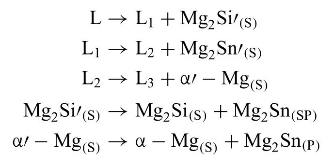
Based on the above discussion,the solidificatio path and precipitate reactions of the microstructure in Fig.1 could be summarized as following:

4.2.Mg2Si phase
4.2.1.Solid solution
According to the pseudo-binary phase diagram optimized by Jung et al.[38],the limited solid solubility of Sn in Mg2Si is about 8.0 at.% at 100◦C,and the solid solubility increases with the increase of temperature,the maximum solid solubility is about 15.0 at.% at 857◦C.However,it has been reported that the typical compositions Mg2(Si0.6Sn0.4)[39,40],Mg2(Si0.5Sn0.5)[41,42] and Mg2(Si0.4Sn0.6)[43] for thermoelectric application have been successfully synthesized by solid state reaction combined with hot pressing or sintering from high purity elements.For above solid solutions obvious phase separation of Mg2Si-rich and Mg2Sn-rich was observed by SEM [40,44].Zheng et al.[43] investigated the microstructure of Mg2(Si0.4Sn0.6)Sb0.018by TEM and found that spherical and ellipsoidal nanoscaled Mg2Sn-rich particles are precipitated from matrix.But still,the content of Sn in Mg2(SiSn)phase prepared by solid solution reaction was much higher than that in present work,which could be attributed to the following two factors: (1) in their studies,the contents of Sn are more than 13.3 at.%;(2) comparing with the solidificatio process,atomic diffusion of Si,Sn and doping element were sufficien due to the long time (1 h to 10 h) holding at high temperature (700◦C to 800◦C) during solid state reaction [40,43–45].
As an important modificatio element,Sb atoms were completely dissolved in Mg2Si and Mg2Sn phase.It is found that in the Mg2(SiSn)solid solution,Sb element with content of 1.8 at.% can impel phase separation into Mg2Si-rich and Mg2Sn-rich phase [43].Xin et al.[45] reported that in Mg2Si the dislocation density and strain accumulation are increased with increase of Sb content,with 6.7 at.% Sb the Mg2Si crystal showed complex microstructure full of defects.In our work,the dissolved Sb content was very low(0.8 at.%),therefore,the central region (region A) in Fig.2a was free of defect (Fig.2b).
4.2.2.Crystal structure and lattice constant
Mg2Si has an anti-fluorit structure with Mg atoms at Wyckoff positionand Si atoms at position 4a(0,0,0)[42].The lattice parameter of pure Mg2Si obtained from XRD experimental result and calculated by first principle are 0.635 nm and 0.636 nm [46],respectively.It is reported that the lattice parameters of Mg2(Si1−xSnx)are increased with the increase of Sn contents [39].Xin et al[45] prepared polycrystalline Mg2Si1−xSbxspecimens by powder metallurgy and found that the lattice parameters of Mg2Si are increased linearly with the increase of Sb contents.Likewise,the lattice parameters also show the linearly incremental relationship with the increase of Sb for Mg2(SiSn)solid solution [43].In previous reports [39,43,45,46] the enlarged lattice parameters are attributed to the successful substitution of Sn and Sb at Si sites due to the sufficien atomic diffusion.Nevertheless,in present work,the lattice parameteraof primary Mg2Si phase was 0.627 nm that was smaller than that of pure Mg2Si phase.HRTEM investigation (Fig.2b)and EDX spectrum (Fig.1b) revealed in primary Mg2Si phase not only the Si sites but also partial Mg sites were substituted by Sn and Sb atoms under conventional solidificatio condition.Because the atomic radius of Sn and Sb are smaller than that of Mg,the primary Mg2Si phase,which actually contained a small amount of Sn and Sb atoms,showed a shrunken lattice parameter.
4.2.3.OR of Mg2Si/α-Mg
An OR between the Mg2Si and α-Mg ofwas reported by Fritz and Hamish in 1988 [47],which was found from eutectic Mg2Si rods andα-Mg matrix in rapidly solidifie Mg-Si alloys.However,the OR between primary Mg2Si phase and α-Mg was different from that between eutectic Mg2Si phase and α-Mg because of the different order of crystallization during solidificatio process.Generally,primary Mg2Si and α-Mg had a almost nonadhesive interface that was indirectly confirme from the tensile fracture morphologies according to the previous reports.During TEM specimen preparation the large primary Mg2Si particle was easily detached from the foil,and homogeneous thicknesses of Mg2Si particle and α-Mg were difficul to be obtained.Thus the OR of primary-Mg2Si/α-Mg by far has rarely been reported.In this paper,an OR ofwas determined by electron diffraction recorded separately from Mg2Si phase and α-Mg without tilting operation,which was also verifie from the OR of Mg2Si precipitate and α-Mg according to the HRTEM analyses (Figs.5 and 6).The corresponding stereogram of this OR was plotted in Fig.7 so as to fin potentially parallel crystal planes between Mg2Si phase and α-Mg,but no more parallel crystal planes were found.In this OR the calculated mismatch of the parallel planes(220)Mg2Si/(012)αand(20)Mg2Si/(20)αwere 16.7% and 32.2%,respectively.It is suggested that there had high surfacial energy and poor matching interfacial structures between Mg2Si phase and α-Mg.
With the modificatio of combined additions of Sn and Sb elements,the incoherent hard-to-soft interface of Mg2Si/α-Mg was improved because two kinds of transitional nanoparticle layers were formed between primary Mg2Si particle andα-Mg (Fig.4).As the main part,Mg2Sn nano-particles distributed in the two layers played an important role in combining primary Mg2Si particle and α-Mg,which had cohesive interfaces (discuss in Section 4.3) with both of Mg2Si phase and α-Mg.

Fig.7.Stereogram of Mg2Si phase and α-Mg.
4.3.Mg2Sn phase
4.3.1.Crystal structure and lattice constant
The calculated and experimental values of lattice parameteraof pure Mg2Sn are 0.681 nm and 0.666 nm [46],respectively.In present study,the lattice constants of Mg2Sn varied with its morphologies.Mg2Sn phase had three morphologies:(1) the nanoscaled particles (Fig.3) precipitated from the rim region of primary Mg2Si crystal,corresponding to the interlayer in Fig.1a;(2) the columnar and granular particles distributed nearby the boundary of the primary Mg2Si phase in Fig.4a,corresponding to the white contrast compound surrounding the primary Mg2Si crystal,and (3) the Mg2Sn precipitated from α-Mg (Mg2Sn-C2 crystal in Fig.6a).The primary Mg2Sn phase contained 6.1 at.% Si and 6.2 at.% Sb with a large lattice constanta=0.813 nm.It is suggested that the expanded lattice constant was attributed to the substitution of Sb at Sn sites.Owing to smaller lattice constant of Mg2Si than that of Mg2Sn,the solid solubility of Sb in Mg2Si phase was smaller than that in Mg2Sn (Fig.1b).Therefore,the Sb content of nanoscale precipitates Mg2Sn in primary Mg2Si was smaller than that in the primary Mg2Sn,resulting in the smaller lattice constant.The lattice constant of the Mg2Sn precipitate in α-Mg was approximate to that of pure Mg2Sn.It is because the Mg2Sn precipitate in α-Mg contained few Sb and Si owing to the limited solid solubility of Si and Sb elements in α-Mg.
4.3.2.ORs of Mg2Sn/Mg2Si
The OR between Mg2Si and Mg2Sn phase has not been reported previously.Although DPs of the circle region in Fig.2a showed polycrystalline rings (Fig.3b),three ORs between Mg2Sn and Mg2Si were found in Fig.3c.Theoretically,the misfi strain between pure Mg2Si and Mg2Sn phase in OR1 was 4.9%.Since the changes of lattice parameter of both Mg2Si and Mg2Sn phase due to the solid solution of Sn and Sb,the calculated misfi strain was about 20.0%.To explain the stability of Mg2Sn/Mg2Si interface,the onedimensional matching model along[110]directions of Mg2Sn and Mg2Si phase is schematically illustrated in Fig.8a.Since the lattice constantaof Mg2Sn phase was about 1.2 times of that of Mg2Si phase,5d(220)Mg2Snwas almost equaled to 6d(220)Mg2Si.Hence,discrete edge dislocations having Burgers vector b=[110] were periodically introduced with a span of 5d(220)Mg2Sito compensate the misfi strain.This kind of interphase was a primary preferred state [48] that has automatically relaxed to a low energy configuration The measured dislocation spacingDwas associated with the calculated value by following formula proposed by Zhang [49]:

Fig.8.Schematically illustrations of plane matching of Mg2Sn and Mg2Si phase in OR1.(a) One-dimensional row-matching of (220) planes;(b) Projected two-dimensional overlapped matching status of Mg,Sn and Si atomic planes from [001] direction,in which the O-points of constraint coincident sites were marked by open circles;(c) edge-on view of one-dimensional matching of (200) planes,in which homogeneous and heterogenous atomic row-matching were marked by open circles and squares,respectively.

In this case,Δb∗was differential value of reciprocal Burgers vectors of 4(110) of Mg2Sn and Mg2Si phase.Interestingly,in the interface of Mg2Si and Mg2Sn phase connective atoms also showed a periodic change of every fi e times spacing of Mg2Sn (220) planes,as indicated by arrows.Although the conterminous atoms from Mg-Si and Mg-Sn changed to Mg-Mg and Si-Sn,the circumambient atoms still retain antifluorit structure.In other words,the change of a small part of local atomic bonding had little effect on the interfacial stability.
Since atomic properties of(001)and(002)planes in Mg2Si and Mg2Sn unit cell are different,four kinds of geometrical models of two-dimensional O-lattices are plotted by superimposing Mg,Si,Sn atomic planes,as shown in Fig.8b.The good matching regions were separated by the intersected traces of O-cell walls (indicated by lines),which were Si or Mg atomic rows of Mg2Si phase depending on different matching forms with a span of 3aMg2Siboth along[110] and [10] directions.Regardless of matching form,the periodically distributed O-points,marked by open circles,were located at the centers of good fit Naturally,in the good matching region in(001)Mg2Si−(001)Mg2Snand(002)Mg2Si−(002)Mg2Snmatching forms,besides the lattice consistency between Mg2Sn precipitate and Mg2Si matrix,the interfacial structure had atomic matching.

Fig.9.(a) Simulated diffraction patterns of Mg2Sn and Mg2Si phase in OR2;(b) the extended diffraction spots along vectors of g(22)Mg2Sn and g(220)Mg2Si;(c) schematically illustration of one-dimensional row-matching along [220]Mg2Si ‖[22]Mg2Sn direction,in which the constraint coincident and good matching planes were marked by open circles and square,respectively.
HRTEM image (Fig.3c) implied the habit planes of C1 precipitate partial were {200} planes.To reveal the interfacial structure along 〈100〉,an edge-on view showing onedimensional matching planes of Mg2Sn and Mg2Si phase is plotted in Fig.8c.It was found that the periodic dislocation configuratio was the same as that along [110] direction (Fig.8a).All lattice points in matching rows were good matching sites,at where the spacing between lattice sites of Mg2Si and Mg2Sn phase was smaller than 20% Mg2Si.The homogeneous atomic rows (Mg-Mg/Si-Sn) matching and heterogenous atomic(Mg-Si/Mg-Sn)rows matching were periodically alternated with every fi e times spacing of(400)Mg2Snplanes.The constraint coincident sites,i.e.,good matching sites with zero misfits were marked by open circles,which were located at the periodic center of homogeneous atomic matching rows.In this case,the interface of Mg2Sn/Mg2Si had low interfacial energy.
The interface of OR2 was hard to be observed from HRTEM image (Fig.3c),meanwhile,the FFT spectra of C3 and Mg2Si phase,which were useful to interpret the interfacial structure,were difficul to be obtained in local area of C3 crystal.Therefore,the overlapped diffraction patterns(Fig.9)by calculation based on measured crystallographic parameters of C3 and Mg2Si phase from HRTEM image were plotted to help analyzing the interphase boundary.Fig.9a revealed 6g(20)Mg2Snwas coincident with 5g(20)Mg2Si.According to Eq.(1),it can be demonstrated that the periodic dislocations with spacing of D=6d(20)=1.33 nm were introduced along [10] direction.The interfacial structure was analogously to that of OR1 along [011] direction(Fig.7a).
Along vectors of g(22)Mg2Sn‖g(220)Mg2Si,coincident reciprocal points of 9g(22)Mg2Snand 13g(220)Mg2Siwere found (Fig.8b).The calculated dislocation spacing wasD=indicating four dislocations were inserted into Mg2Sn/Mg2Si interphase boundary with Burgers vector of[11]in a span of 13d(22)Mg2Sn.The one dimensional mismatch of(220)Mg2Siand(22)Mg2Sn,illustrated in Fig.9c,showed a secondary preferred state[48].It is obvious that the interface was in an un-relaxed state,which consisted fractional coincident sites (marked by open circles) and good matching sites (marked by squares).Therefore,it is reasonable to deduce that the potential habit planes of Mg2Si precipitate in OR2 were {224} planes.
The morphology of C4 particle in OR3 was nearly a square rotated 45◦around the axis normal to paper.Since the nearly equal interplanar spacing of(13)Mg2Snand(220)Mg2Si,Mg2Sn and Mg2Si showed evident edge-to-edge interfacial feature along [13]Mg2Sn‖[110]Mg2Sidirection,as seen from HRTEM image(Fig.3c).In order to fin out potential parallel planes with nearly equal interplanar spacing between Mg2Sn and Mg2Si phase,simulated overlapped diffraction patterns of them are plotted in Fig.10a.After extending the diffraction patterns by calculation,it is found that(40)Mg2Snwas almost parallel to(220)Mg2Siwith only a deviation of 0.8◦,and 8g(200)Mg2Snwas matched well with 3g(40)Mg2Si,suggesting the constraint coincident sites were presented with a span of 3d(200)Mg2Snor 8d(40)Mg2Si.
Actually,white points of C4 crystal in HRTEM image corresponded to Sn atomic columns.To reveal interfacial structure,the effect of Mg atoms should be considered.Because the large facets of C4 precipitate was approximatively parallel to (200) and (020) planes of Mg2Si matrix,so an edgeon view from [100]Mg2Siis illustrated in Fig.10b.Clearly,the Mg rows of Mg2Sn,i.e.,(400) plane,which were absent in HRTEM image,were alternate with Sn rows,and(13)plane of Mg2Sn did not contain Mg atoms.Herein,it is unconvincing to interpret the interfacial stability if only consider matching state of the parallel planes of(13)Mg2Snand(220)Mg2Si.On the large facet,marked by solid line in Fig.10b,each Mg or Sn row in Mg2Sn had corresponding matching row with Mg2Si although a few matching rows had slight lattice strain.The ideal edge-on matching rows were indicated by circles,which had a periodicity of 3d(200)Mg2Snor 8d(40)Mg2Sias predicted by overlapped DPs in Fig.10a.In a period,one in six rows was heterogenous atomic rowmatching as marked by square,and fi e rows were homogeneous atomic row-matching.This kind of edge-on rowmatching had a strong effect on reduction of interfacial energy.
In the three ORs,Mg2Sn precipitates and Mg2Si matrix had strong bonding interfaces.Comparing the interfacial structures of above three ORs,due to the particularity of the periodic structure of OR1,the precipitate in OR1 had singular interfaces with Mg2Si phase in three dimensions associated with a local minimum of the structural component of interfacial energy.That is to say the precipitate in OR1 had the lowest surfacial energy than other ORs.Hence,C1 precipitate was favor to grow up to large size.During TEM observation,we examined a number of primary Mg2Si particles by electron diffraction and HRTEM,and found that in region B precipitates with OR1 had the largest proportion.

Fig.10.(a)simulated diffraction patters of Mg2Sn and Mg2Si phase in OR3.(b) projected row-matching from [100]Mg2Si direction,the edge-on matching rows were marked by circles,and heterogenous matching rows were marked by squares.
4.3.3.ORs of Mg2Sn/α-Mg
The ORs of Mg2Sn/α-Mg were widely studied due to the rich precipitation crystallography in Mg-Sn system.At present,thirteen ORs between Mg2Sn phase and α-Mg were reported [50–57].A near row matching approach was applied to predict and interpret the precipitation crystallography of α-Mg/Mg2Sn system [56,57] and found that the phase boundaries in above ORs have row-matching interfacial structures with low surfacial energy.Figs.5 and 6 showed three ORs.In order to investigate whether the ORs found in this paper belong to those in previous reports,the stereograms of the three ORs were plotted according to the experimental values of lattice constants,as shown in Fig.11,and potentially parallel crystal directions and crystal planes between Mg2Sn phase and α-Mg were explored by stereographic projects.Based on comparative analysis of the three ORs and the known ORs,we confirme these three ORs were new ORs.
In OR1 the parallel crystal planes of(13)Mg2Snandhad almost equal interplanar spacing,which implied Mg2Sn phase and α-Mg matrix had a edge-to-edge matching interface with low interfacial energy.In fact,according to the lattice constants of pure Mg2Sn phase and pure Mg,the calculated misfi of the two crystal planes was 20.3%.Therefore,its stable interfacial structure could be ascribed to the enlarged lattice constants of Mg2Sn phase.It is noted that in OR1 (Fig.11a) [111] zone axis was close to[0001]αwith an accuracy of 7.6◦.Similarly,the angular distance ofwas 5.9◦,while the deviation ofwas 6.7◦.Herein,an OR with lowindex in form of[111]Mg2Sn‖[0001]α,andcould be achieved by slightly rotating Mg2Sn crystal with a few degrees,which was equivalent to the OR4 reported by Shi et al.[56].In Figs.5 and 6 the lattice constants of Mg2Sn-C2 crystals were close to that of pure Mg2Sn,it suggested that the phase contained few Sb element.The mismatch of the parallel planes of(220)Mg2Snandwas 26.3%,which was larger than the requirement of critical misfi (10%) in edgeto-edge matching [58].However,Mg2Sn-C2 crystals with OR2 had a coherent interface with Mg2Sn-C1 crystals because the parallel planes of(20)C2and(3)C1(Fig.5),(220)C2and(13)C1in Fig.6 had nearly equaled interplanar spacing.Therefore,it is reasonable to conclude that Mg2Sn-C2 crystals were precipitated based on Mg2Sn-C1 crystals from α-Mg matrix rather than primary Mg2Sn phase.In OR2(Fig.11b) if Mg2Sn crystal was rotated anti-clockwise about 9.8◦around [10] zone axis,the [111]Mg2Snaxis was aligned with [0001]αaxis and [2]Mg2Snaxis was coincident withaxis.The OR was changed to be(111)Mg2Sn‖(0001)α,which was a variation of OR3 as described in previous report [56].
Similar to OR1,in Fig.6 Mg2Sn-C1 crystal in OR3 had an edge-to-edge matching interface with α-Mg due to the equal interplanar spacing of parallel(311¯)Mg2Snandplanes.In Fig.11c,except the approximate parallel zone axes of [121]Mg2Siand [0001]α,no more potential coincident lowindex zone axes of Mg2Sn and α-Mg were found by stereographic project.
The three ORs were not predicted by the near row matching approach.According to previous discusses,it could be ascribed to the following two factors: (1) the Mg2Sn phase was primary phase rather than precipitate phase,the solidificatio of which was prior to the α-Mg matrix;(2) in the near row matching approach the lattice constants of α-Mg are a=0.3209 nm and c=0.5211 nm,and a=0.6763 nm for Mg2Sn [57],however,in present work,the lattice constants of both Mg2Si and α-Mg were changed owing to solid solution of Sn and Sb atoms,especially the enlarged lattice of Mg2Si phase,which led to the changes of interplanar spacing.Therefore,the three new ORs were minor ORs.

Fig.11.Stereograms of Mg2Sn and α-Mg of (a) OR1,(b) OR2 and (c) OR3.
5.Conclusions
The detailed microstructures of primary Mg2Si phase and Mg2Si/α-Mg interface modifie by Sn and Sb elements in an as-cast Mg-5Sn-2Si-1.5Al-1Zn-0.8Sb alloy were investigated.The main conclusions are summarized as follows:
1.With the modificatio of combined additions of Sn and Sb,two transitional nano-particle layers formed between primary Mg2Si and α-Mg matrix.In the rim region of primary Mg2Si particle,Mg2Sn precipitates having size from 5 nm to 30 nm distributed in Mg2Si matrix.Adjacent to the boundary of primary Mg2Si particle,luxuriant columnar crystals of primary Mg2Sn phase with width of about 25 nm and length of about 100 nm were distributed on the α-Mg matrix,the tails of which were discontinuous.The solidificatio path and precipitate reactions were:
2.In primary Mg2Si phase not only the Si atoms but also the Mg atoms could be substituted by Sn and Sb atoms.Though Mg2Si still retained anti-fluorit structure,the lattice constant was slight reduced to 0.627 nm.
3.The Mg2Sn precipitate in primary Mg2Si particle had a lattice constantaof about 0.756 nm.Three ORs between Mg2Sn and Mg2Si were found.They were[001]Mg2Sn‖[001]Mg2Si,(100)Mg2Sn‖(100)Mg2Si(OR1),[111]Mg2Sn‖[001]Mg2Si,(22)Mg2Sn‖(220)Mg2Si(OR2),and[013]Mg2Sn‖[001]Mg2Si,(13)Mg2Sn‖(220)Mg2Si(OR3),respectively.In the three ORs,Mg2Sn precipitates had strong bonded interfaces with Mg2Si matrix,and the OR1 had the lowest surfacial energy,in which the precipitates were favor to grow up to large size and had the largest proportion.4.Three new ORs between Mg2Sn and α-Mg were found:andThe primary Mg2Sn phase in OR1 and OR3 with an enlarged lattice constant ofa=0.813 nm had edge-to-edge matching interfaces with α-Mg.The three ORs were minor ORs,it was ascribed to following two factors: (1) the solidificatio of primary Mg2Sn phase was prior to the α-Mg matrix and (2) the lattice constants of Mg2Sn phase were enlarged owing to the solid solution of Sb atoms.
5.The primary Mg2Si and α-Mg with an OR ofhad a poor interfacial structure.However,the nonadhesive primary Mg2Si particle and α-Mg were united and improved by the two nano-particles layers of Mg2Sn phase.
Acknowledgements
This work was supported by the National Natural Science Foundation of China[51571086];and Research Fund for Doctoral Program of Henan Polytechnic University [B2015-14].
杂志排行

Journal of Magnesium and Alloys的其它文章
- Effect of crystallization on purity of volatile metallic magnesium prepared from a one-step multi-region condensation process under vacuum condition
- Tribological behaviour of AZ31 magnesium alloy reinforced by bimodal size B4C after precipitation hardening
- Thermodynamic assessment of Mg−Ni−Y system focusing on long-period stacking ordered phases in the Mg-rich corner
- Quasi-in vivo corrosion behavior of AZ31B Mg alloy with hybrid MWCNTs-PEO/PCL based coatings
- The microstructure evolution and deformation mechanism in a casting AM80 magnesium alloy under ultra-high strain rate loading
- Evaluation of corrosion resistance,mechanical integrity loss and biocompatibility of PCL/HA/TiO2 hybrid coated biodegradable ZM21 Mg alloy