Fabrication of graphene nanoplatelets reinforced Mg matrix composites via powder thixoforging
2022-12-30PingoWngJunShenTijunChenQinglinLiXioYueLingyunWng
Pingo Wng,Jun Shen,Tijun Chen,Qinglin Li,Xio’n Yue,Lingyun Wng
a State Key Laboratory of Solidificatio Processing,Northwestern Polytechnical University,Xi’an,710072,China
b State Key Laboratory of Advanced Processing and Recycling of Non-ferrous Metals,Lanzhou University of Technology,Lanzhou,730050,China
Abstract A powder thixoforging route combined with slurry based mixing process was proposed to fabricate graphene nanoplatelets (GNPs) reinforced magnesium matrix composites (MgMCs).The originally spherical and ball-milled ZK60 powders were used as matrices,respectively.The mixing of 0.05wt.% GNPs with the spherical powder led to GNPs clusters and degraded the mechanical properties of the composite.In contrast,with the addition of an optimal content (0.1wt.%) of GNPs,the composite fabricated from ball-milled powder achieved a joint enhancement in tensile yield strength (52%) and fracture toughness (19%),demonstrating a pronounced strengthening efficien y of 650% and a good balance between strength and toughness.The ball-milled powder endowed the composite with a homogenous distribution of GNPs and a denser microstructure with reduced Mg-Zn eutectics,and the thixoforging process offered a well-bonded Mg/GNP interface,making full use of the strengthening and toughening potential of GNPs.Theoretical predication based on a modifie shear-lag model suggested that load transfer dominated the strengthening mechanisms.In-situ tensile tests verifie that crack deflection secondary cracks and GNPs bridging mainly accounted for the toughening mechanisms.A numerical model with consideration of GNPs orientations was also established to understand the toughening effect from GNPs bridging.
Keywords: Graphene nanoplatelets (GNPS);Magnesium;Powder thixoforging;Strengthening;Toughening.
1.Introduction
Magnesium alloys are increasingly attractive for lightweight and energy saving applications in aerospace,automobile,electronics and sports-related industries,owing to their benefit such as low density,high specifi strength and stiffness,good damping capacity and recyclability [1,2].Nevertheless,their wide applications are seriously restricted as a result of the relatively low strength and poor ductility[3].Incorporation of reinforcing particles into alloys to obtain metal matrix composites (MMCs) has large potential to improve their mechanical properties.However,traditional micron oxide or ceramic reinforcing particles generally lead to the reduction in ductility.Previous studies have revealed that the addition of a small volume fraction of nanofiller could improve the strength of matrix without sacrificin the ductility/toughness,and offer the higher strengthening efficien y compared with micron particles [1].Accordingly,novel reinforcements with superb properties are hopeful to surmount the trade-off between strength and ductility that has plagued traditional MMCs [4].
Graphene is being an attractive reinforcing nanofille in MMCs because of their ultra-high tensile strength (up to 130 GPa) and elastic modulus (∼1 TPa),and other outstanding physical characteristics such as high thermal conductivity and low thermal expansion coefficien [5].Compared with ceramic or oxide nanoparticles and carbon nanotubes (CNTs),the unique 2D geometry and large aspect ratio of graphene are favorable for a more effective load transfer from matrix to reinforcement [6,7] in MMCs.Usually,graphene nanoplatelets(GNPs) composed of multilayer graphene are preferred to be used as an alternative reinforcement for high-performance MMCs,because they are much easier to obtain and cost less than graphene,yet offer comparable strengthening efficien y[8].However,obtaining the uniform dispersion of GNPs into metal matrix remains challenging due to their large specifi surface area and poor wettability with metal melts,which really becomes a bottleneck in the fabrication of MMCs reinforced with GNPs.
Until now,processing techniques of GNPs reinforced magnesium matrix composites (MgMCs) can be mainly classifie into two kinds: solidificatio processing and powder metallurgy.Basically,solidificatio processing is regarded as an effective pathway in terms of cost-effective and mass production.In this case,the traditional casting method has realized the incorporation and dispersion of GNPs into molten matrix through assisted technologies such as ultrasonic processing [7,9],semisolid stirring [7,10] and diluting precursor containing GNPs [10,11].Also,relatively novel methods like disintegrated melt deposition (DMD) [12–14]and semisolid processing [15,16] have been proposed to pursue a homogeneous distribution of GNPs in metal matrix.Nevertheless,nearly all these methods combined multiple dispersing means or steps to diminish the tendency of GNPs agglomeration.Moreover,additional deformation like hot extrusion [11,13,15] and friction stirring processing [9] is generally needed to further improve the dispersion and distribution of GNPs,and also enhance the interface bonding between GNPs and matrix,resultantly making the fabrication process more tedious and less practical in mass production.Furthermore,the relatively high processing temperature may impair the graphene structure through interfacial reactions[16].Alternatively,powder metallurgy is considerably popular in producing MMCs reinforced with nanoparticles owing to the efficien dispersion of reinforcement,fl xible constituent design and controllable interface reaction[17].This technique always involves three steps: mixing of powders,compacting of powder mixtures and sintering of green compact.However,additional deformation processing like hot extrusion or rolling is also indispensable for further consolidation.It should be pointed out that the commonly-used ball milling,being an economical and effective method to produce powder mixtures,may be still ineffective for uniformly dispersing GNPs in metal matrix because of the large specifi surface area and the attractive Van der Waals forces between graphene layers.Meanwhile,the improper milling parameters will damage the graphene structure and promote interfacial reactions,and hence impair the strengthening efficien y[18].To tackle these issues,improved methods such as semi-powder metallurgy or modifie powder metallurgy[19–21],fla e powder metallurgy[22,23] and graphene surface modificatio [24–26] have been proposed,which was expected to improve the compatibilities of GNPs and metal powders in terms of geometries and/or surface properties to achieve homogeneous distribution of GNPs in metal powders.Moreover,GNPs were usually mixed with metal powders in a solvent (e.g.ethanol) using mechanical stirring instead of ball milling to maintain the structural integrity of GNPs.Although these methods have made progress in uniformly distributing GNPs into metal matrix,the obtained microstructure still exhibits low density level and poor interfacial bonding,while the required post-processing step makes the process more complicated.Therefore,they are neither reliable nor cost-effective enough to produce complexshaped components.Thus,a more effective and facile route to fabricate MMCs reinforced with GNPs is highly desired.
It is well known that thixoforming is favorable for obtaining dense microstructures and forming large components with complex shapes,and has been considered as a potential route for processing MgMCs [27].The key to this technique is to get semisolid ingot with non-dendritic microstructure,which can be easily obtained by reheating the green compact of atomized alloy powder at a semisolid temperature.Thus,powder thixoforming have been proposed to produce MMCs with desired mechanical properties in our previous works [28,29].This hopeful method combines the benefit of powder metallurgy and semisolid processing,not only allowing a uniform distribution of reinforcing particles and a dense microstructure,but also being sophisticated enough to fabricate complex-shaped and large-sized parts.Moreover,it is free from multistep processing typically required in powder metallurgy process and high forming temperature associated with fully liquid processing.
On the basis of the viewpoints above,we made an attempt to fabricate ZK60-GNPs composites using powder thixoforging in this study.For comparison,the ball-milled and nonmilled ZK60 powders were mixed with GNPs through a wet mixing process and then consolidated into bulk composites by thixoforging,respectively.The influence of alloy powder shapes and GNPs content on the distribution of GNPs within matrix,microstructures and mechanical properties of composites were investigated.The possible strengthening mechanisms were theoretically analyzed.Also,the relevant toughening mechanisms were explored via in-situ tensile SEM observation,followed by numerical modeling.
2.Experimental
2.1.Raw materials
Atomized ZK60 magnesium powder (Mg-5.20Zn-0.33Zr,supplied by Tangshan Weihao Magnesium Powder Co.,Ltd.,China) and GNPs (3–10nm in thickness,1–7μm in lateral size,Nanjing XFNano Material Tech Co.,Ltd.,China) were used as raw materials.As can be seen,the alloy powder is regularly spherical and consists of many small equiaxed grains with a mean particle size of 19μm (Fig.1(a) and (b)),and the used GNPs exhibit a 2D structure with small thickness of∼5nm (Fig.1(c) and (d)).
2.2.Fabrication of composites

Fig.1.(a) SEM image and (b) particle size distribution of as-received ZK60 alloy powder;(c) SEM and (d) TEM image of raw GNPs.

Fig.2.Schematic illustration of the preparation process for ZK60-GNPs composites by powder thixoforging.
The fabrication process for ZK60-GNPs composites by powder thixoforging is schematically depicted in Fig.2,which contains four steps:powder mixing,compacting,partial remelting and thixoforging.
The spherical ZK60 powder was initially ball milled to obtain an irregular powder shape under the protection of argon gas.The ball-to-powder mass ratio,rotation speed and milling time were 10:1,200rpm and 4h,respectively.In the meantime,the raw GNPs were pre-dispersed by tip-sonication in ethanol for 2h to achieve a uniform suspension.Subsequently,the slurry based mixing process [19] was employed to mix GNPs with the ZK60 powder.The ball-milled powder was mechanically stirred in ethanol to form slurry,and then the pre-dispersed GNPs suspension was added dropwise under continuous stirring to obtain the mixed slurry.To avoid the floatin and re-agglomerating of GNPs,the mixed slurry was bathed in water (50°C) and continuously stirred until in semi-dry state,and then was vacuum-dried at 60°C for 12h to obtain the mixed powders.About 60g mixed powders were compacted in a homemade vacuum mold at 180°C into a green compact (∼Φ50×16mm),using a pressure of∼300MPa.Then the green compact was partially melted in a tubular furnace under argon atmosphere by isothermally holding at a targeted semisolid temperature of 630°C for 60min to obtain semisolid billet for thixoforging.Finally,the semisolid billet was transferred rapidly into a preheated (300°C) steel die cavity with a diameter of 55mm and forged immediately under a pressure of ∼240MPa and holding for 20s to produce fina composite (define as BM-GNPs composite).
For comparison,the original i.e.,non-milled ZK60 powder was mixed with GNPs to forge NM-GNPs composite through the same procedure.The unreinforced NM and BM alloys were also thixoforged by directly compacting non-milled and ball-milled powder,respectively.
2.3.Characterization
The phases of the starting materials and fina composites were analyzed by X-ray diffraction (XRD,Rigaku D/Max-2500).The distribution of GNPs within matrix,as well as the microstructures and fracture morphology of thixoforged samples were examined using a scanning electron microscope(SEM,JSM-6100F) equipped with an energy-dispersive spectroscopy (EDS).The microstructures of the thixoforged samples were also observed by an optical microscope (OM,Axio Scope A1).The interface structure of the thixoforged composite was investigated by using a transmission electron microscope (TEM,JEOL JEM-F200S).In-situ tensile tests were performed on a Quanta FEG 450 SEM to observe the fracture process of the thixoforged materials.To examine the mechanical strength,tensile and compression tests were conducted on a universal machine (AGS-X 300KN,Shimadzu Co.,Ltd.,Japan) with strain speed of 1×10⁻³s−1.For each material,fi e dog-bone shaped specimens (gauge length: 12.5mm;cross section: 5mm×2mm) and three cylindrical specimens(Φ8×12mm) were used for tensile and compression tests,respectively.The micro-hardness was measured by utilizing a micro-hardness tester (HV,W1102D37,Buehler Ltd.,USA)with a load of 100g and a dwell time of 10s.
3.Results and discussion
3.1.Uniformity of GNPs distribution within the matrix powders
Fig.3 shows the SEM images of the mixed powders.It is apparent that the ball-milled powder exhibited irregular shape and rougher surface.Also,the distribution of GNPs within matrix powder was strongly dependent upon GNPs concentration and powder shape.Within the ball-milled powder,a uniform distribution of GNPs was obtained by adding no more than 0.1wt.% GNPs.As seen in Fig.3(a–d),the welldispersed GNPs (denoted by yellow circles and arrows) were adhered onto the powder surface without obvious agglomeration.However,the addition of 0.15wt.% GNPs formed clusters either on the powder surface or among the powder particles (indicated by red circles and arrows,Fig.3(e) and (f)),indicating an inhomogeneous distribution of GNPs.Within the non-milled powder,GNPs were distributed non-uniformly,even if the content was as low as 0.05wt.%.As observed in Fig.3(g)and(h),most GNPs agglomerated among the spherical particles (as marked by red circles and arrows),with only a small amount of them dispersed onto the powder surface(marked by yellow circles).
The compatibility in morphology between matrix powder and GNPs plays a key role in the distribution homogeneity of GNPs within matrix.Compared with GNPs with 2D geometry and large specifi surface area,spherical metal powder is featured with smooth surface and large curvature,which will limit the adhesion of GNPs to powder surface.Whereas,the irregularity of ball-milled powder can weaken the curvature effect and increase the actual contact area between the metal powder and GNPs,improving the compatibility in morphology [30].Accordingly,the ball-milled powder could accommodate more GNPs than the non-milled powder,achieving a uniform distribution of GNPs within the matrix.
3.2.XRD results
Fig.4 presents the XRD patterns of the starting materials and samples obtained from the different fabrication steps.It was evident that no diffraction peaks of GNPs were detected in the mixed powders and fina composite due to the low content of GNPs.The absence of peaks related to interfacial products was consistent with the fact that ZK60 would not react with GNPs.In addition,the intensity of MgO peaks in the fina composite was slightly higher due to high temperature during the partial remelting process.
3.3.Microstructure characterization
Firstly,there is a need for a basic description associated with the as-thixoforged microstructures.After partial remelting,the fin grains inside ZK60 powder particle are coarsened seriously and no longer remained due to a long-time holding at high temperature.In turn,the unmelted portion of one powder particle will mostly evolve into oneα-Mg particle or sometimes be separated into severalα-Mg particles by liquid,all of which are described as primaryα-Mg particles.Besides,during thixoforging,some small grains are solidifie from liquid phase,namely secondα-Mg grains.
Fig.5 gives the optical micrographs of as-thixoforged alloys and composites.All the microstructures presented the primaryα-Mg particles (marked by arrows A) with clear particle boundaries (PBs,dark regions),along with some fin secondaryα-Mg grains (marked by arrows B).Moreover,the primaryα-Mg particles in the samples fabricated from non-milled powder (Fig.5(e) and (f)) were more round than those obtained from ball-milled powder (Fig.5(a-d)),indicating that the as-thixoforged microstructure partially inherited the feature of original powder.It has been reported that the addition of GNPs could markedly refin the grains by acting as nucleation substrates forα-Mg during solidificatio[12,13,16] or pinning grain boundaries to hinder grain growth during sintering [31].As shown in the insets of Fig.5,however,there was no dramatic decrease inα-Mg particle size of the composites,indicating an insignifican refinin effect of GNPs on theα-Mg particles.The reasons for this could be:(i) the primaryα-Mg particles in as-thixoforged microstructures evolved from the corresponding powder particles[32]instead of solidification thus their average size was largely determined by that of the powder particles;(ii) the naturally formed oxides on powder surface suppressed the growth of primaryα-Mg particles via pinning up the PBs,the pinning effect of GNPs on PBs was not fully exerted accordingly.Meanwhile,this suppressed growth of primaryα-Mg particles was also evidenced by the minor change from raw powder to primary α-Mg of unreinforced alloys in terms of average particle size,which increased from 19.2μm for the raw powder to 23.7μm for the BM alloy and to 24.4μm for the NM alloy.

Fig.3.SEM images of mixed powders: (a) and (b) BM-0.05GNPs;(c) and (d) BM-0.1GNPs;(e) and (f) BM-0.15GNPs;(g) and (h) NM-0.05GNPs.
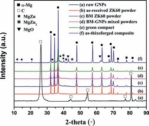
Fig.4.XRD patterns of the starting materials and samples obtained from different fabrication steps.
Fig.6 exhibits the SEM images and element maps of the BM-0.1GNPs.As indicated in Fig.6(b) and (c),an intense carbon (C) accumulation identifie the white strip-like phase as GNPs.Hence,it can be inferred that GNPs were distributed alongα-Mg PBs,accompanied by a fin dispersion of oxides.In this case,the inevitable absorption of oxygen on powder surface,as well as the easy adsorption of oxygen by GNPs because of their wrinkle surface [7] would form oxides especially at high temperature,which affected the mechanical properties of resultant composites.On the other hand,the presence of these oxygen atoms is advantageous to the interfacial bonding between Mg matrix and GNPs due to their preferential reaction with active Mg under high temperature[33].
Fig.7 shows the TEM observation of BM-0.1GNPs.As shown in the inset of Fig.7(a),the selected area diffraction(SAED) patterns indicated that the Mg/GNP interface structure was composed of GNPs and Mg.The fast Fourier transform (FFT) pattern of region B also manifested the characteristic (002) diffraction spots of C,as displayed in the inset of Fig.7(b).According to the noise-filtere inversed FFT image in Fig.7(c),the lattice spacing was measured as 0.3418nm,which further identifie the few-layered graphene structure of GNPs.As can be seen from the HRTEM image provided in Fig.7(b),small GNPs were embedded in the Mg matrix and no obvious gap at the Mg/GNP interface was observed.This suggests that the thixoforging process was adequate to achieve a tight interface bonding.The sufficiently-bonde interface was attributed to the improved wettability at relatively high remelting temperature and forging pressure,and could promote the mechanical interlocking and load transfer between GNPs and Mg matrix.
Fig.8(a–d)compare the SEM(BSE model)microstructures of the two types of ZK60 alloys and their composites.The EDS results indicated that the black point A contained a high level of oxygen and a certain amount of carbon (Fig.8(e)),and the white point B was rich in Zn (Fig.8(f)),corresponding to pores and coarse Mg-Zn phases,respectively.It can be deduced that both pores and coarse Mg-Zn phases appeared heavily in the NM alloy and NM-GNPs composite,but were not distinct in the BM alloy and BM-GNPs composite.The unwanted pores were caused by two factors: (i) the spherical powder was associated with a more porous powder compact due to its low compressibility [34];(ii) GNPs clusters within the spherical powder would remain and generate pores in the fina composite,which was evidenced by the detectable C element in point A and the fact that pores in the NM-GNPs composite were more than those in the NM alloy.With respect to the coarse Mg-Zn phases,they were regarded as the secondary eutectics from solidificatio [15] and therefore related to the formation of liquid phase in semisolid microstructure,which could be understood with the aid of the water-quenched microstructure (Fig.9) of non-milled powder compact (∼Φ12×5mm) partially remelted at 630°C for 30min.As seen in Fig.9(b),someα-Mg particles were enriched by liquid network (marked by arrows A),while others only involved isolated liquid phase (denoted by arrows B) or liquid-free zones (indicated by arrows C).Such liquid segregation should result from the compositional segregation in the original alloy powder,because this liquid phase derived mainly from the melting of the eutectics within alloy powder particles.During solidification the liquid-rich zones preferred to form coarse secondary eutectics due to the preferential concentration of Zn and Mg in melt [35].Maybe the high-density dislocations introduced by ball milling promoted the dissolution of eutectics within powder particles during partial remelting,and thus decreased the segregation of liquid in the corresponding semisolid microstructure,reducing the coarse secondary eutectics in the BM-GNPs composite[32].
On the other hand,previous studies have reported that GNPs could refin the eutectics in the related MgMCs.For instance,Torabi Parizi et al.[15] considered that GNPs inhabited the atomic diffusion and enhanced the cooling rate,promoting the dissolution of the Mg17Al12eutectics in the AZ80/GNPs composites.Rashad et al.[13] assumed that GNPs could regulate the precipitation of Mg17Al12phase and help to dissolve Mg17Al12intermetallic network in the AZ61/GNP composite.As shown in Fig.8(b) and (d),the coarse Mg-Zn phases (marked with arrows) were still discernible in the BM alloy but nearly disappeared in the BMGNPs composite.Therefore,it was speculated that GNPs could similarly refin the secondary eutectics.Due to the agglomeration of GNPs in the matrix,the secondary eutectics in the NM-GNPs composite were refine insignificantl.Anyway,the reduction of pores and coarse eutectic phases was beneficia for the desired properties of composite.
3.4.Mechanical behaviors

Fig.5.Optical micrographs of the thixoforged monolithic alloys and composites: (a) BM ZK60;(b) BM-0.05GNPs;(c) BM-0.1GNPs;(d) BM-0.15GNPs;(e)NM ZK60;(f) NM-0.05GNPs.
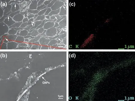
Fig.6.SEM images with the EDS results for the BM-0.1GNPs composite.

Fig.7.(a) TEM image of BM-0.1GNPs,the inset is the SAED patterns of region A;(b) HRTEM image of region A in (a),the inset is the FFT image of region B;(c) the corresponding lattice spacing measurement recorded at region B in (b).

Fig.8.SEM backscattered images and the EDS analysis of marked points: (a) NM ZK60;(b) BM ZK60;(c) NM-0.05GNPs;(d) BM-0.05GNPs;(e) and (f)the EDS results of point A and point B in (c),respectively.(For interpretation of the references to color in this figur legend,the reader is referred to the web version of this article.)

Fig.9.(a) water-quenched microstructure of NM powder compact remelted at 630 °C for 30min and (b) the local magnifie image in (a).
Fig.10(a) and (b) present the tensile and compressive stress-strain curves of the fabricated samples.The strength and fracture strain obtained from tensile and compression tests are also illustrated in Fig.10(c) and (d),respectively.For the unreinforced samples,the BM alloy was stronger and more ductile than the NM alloy.The reason may be that,as stated above,the ball-milling was beneficia for a denser microstructure with reduced secondary eutectics.For the composites,the ultimate tensile stress (UTS) and elongation of the NM-0.05GNPs decreased simultaneously compared to the NM alloy,as a result of the poor dispersion of GNPs within the non-milled powder.Encouragingly,a small percentage of GNPs triggered an appreciable strength enhancement of the BM-GNPs composites without significan loss of fracture strain,verifying the strengthening potential of GNPs.The BM-0.1GNPs exhibited noticeably the highest strength,while the fracture strain almost remained unchanged.The tensile yield stress (TYS,202MPa) and UTS(310MPa) were increased by 52% and 24%,and the compressive yield stress (CYS,221MPa) and ultimate compressive stress (UCS,509MPa) were also enhanced by 53% and 13%,respectively,in comparison with those of the BM alloy,demonstrating a good strength-ductility balance.With the addition of 0.15wt.% GNPs,the strength of composite dropped down clearly.This indicated that an excess of GNPs weakened the mechanical properties of composite due to the agglomeration of GNPs.The Vickers hardness and elastic modulus of samples followed a similar trend.As shown in Fig.10(e),there was a slight increase in both hardness and elastic modulus for the BM-0.05GNPs and BM-0.1GNPs.Another hallmark of mechanical behavior for the composites is considered as toughness,which can be evaluated by integrating the tensile stress-strain curve to the fracture point[36].As illustrated in Fig.10(e),the BM-0.05GNPs and BM-0.1GNPs exhibited a toughness of 22.8MJ/m3and 23.7MJ/m3respectively,corresponding to 15% and 19% enhancement over the BM alloy(19.9MJ/m3),owing to a better synergy between strength and ductility.

Fig.10.Mechanical properties of the thixoforged samples: (a) tensile stress-strain curves;(b) compressive stress-strain curves;(c) TYS,UTS and elongation;(d) CYS,UCS and fracture strain;(e) hardness,elastic modulus and toughness.
The strengthening efficien y(R)is commonly used to evaluate the strengthening effect of GNPs,which is given by[36]:

whereσycandσymare the yield strength of composite and matrix,respectively,VGis the volume fraction of GNPs.Fig.11 compares the strengthening efficien y and mechanical properties in this work with those of Mg-GNPs composites reported in available literature.As indicated in Fig.11(a),Rvaried in a wide range of 11%–1550% with the major distribution of 100%–200%,and the BM-0.1GNPs obtained a relatively high strengthening efficien y of 650%,outperforming most other Mg-GNPs composites.Moreover,considering that the YS of these composites ranged basically from ∼110MPa to ∼250MPa with the elongation mostly distributed between 7% and 12% (Fig.11(b)),the as-thixoforged sample,without any post processing,exhibited a good combination of strength and ductility.Unfortunately,nearly all the reported composites,whether by solidificatio processing or powder metallurgy,have suffered from multiple dispersing and/or mixing procedures as well as additional deformation,which makes them less practical in mass production.Therefore,it can be expected that powder thixoforging is more preferable in developing graphene reinforced MMCs,attributed to the considerable mechanical properties of composite and the relatively simple processing process.

Fig.11.Comparison of (a) the strengthening efficien y and (b) tensile properties of the GNPs reinforced MgMCs [37].
Fig.12 presents the fracture morphology of the BM alloy and its composites.All the tensile fracture surfaces presents ductile dimples and facets (indicated by red arrows) typical of brittle fracture,demonstrating a mixed failure mode.In particular,apart from small dimples (pointed out by white arrows) as observed on the fracture surface of matrix,the larger ones (marked with dotted circles) are also associated with composites,at the bottom of which some GNPs can be found,implying that stress can be transferred from Mg matrix to GNPs [39].Meanwhile,some GNPs are observed to be either parallel or perpendicular to the load direction,as shown in Fig.12(d),further confirmin the random distribution of GNPs in the matrix.Generally,the spatial distribution of GNPs can influenc the mechanical properties of composites greatly,and the well-alignment of GNPs parallel to the axis stress is more efficien in the load transfer [20,38].As shown in Fig.12(e),as GNPs content is increased to 0.15wt.%,more micro-cracks (denoted by blue arrows) and fracture facets appear on the fracture surface,which is related to the agglomeration of GNPs.Reasonably,GNPs clusters will hinder the densificatio of composite and initiate more cracks,leading to the premature failure of material at low stress level,as evidenced by the presence of GNPs clusters at cracks,together with a void (Fig.12(f)).The typical compressive fracture surfaces of BM alloy and BM-0.1GNPs present shear bands without observable voids (Fig.12(g) and (h)).Conclusively,the characteristic of fracture surface is consistent with the mechanical properties of the corresponding composites.
In all,the well-dispersed GNPs can contribute to the enhanced mechanical properties via efficien load transfer,while the GNPs clusters will weaken the strengthening effect and even deteriorate the mechanical properties mainly due to the weak bonding between graphene layers.More importantly,factors including the distribution of GNPs,Mg/GNP interface bonding,primaryα-Mg and second eutectics as well as microstructural defects can be tailored via the ball milling and the solidificatio processing in the thixoforging process,enabling the high strengthening efficien y and acceptable mechanical properties of BM-0.1GNPs [40].
3.5.Strengthening mechanisms
A basic understanding of strengthening mechanisms may be helpful to the development and fabrication of advanced MMCs for structural engineering applications.The remarkably higher strengthening efficien y of GNPs than ceramic reinforcements depends greatly on the effective load transfer from matrix to GNPs through interfacial shear stress,owing to their large aspect ratio [41].Furthermore,metallurgical factors including grain refinin effect and dislocations also contribute to the strengthening effect [42].It should be noted that Orowan looping mechanism,generally more pronounced in MMCs with ceramic nanoparticles distributed in the grains[43],contributes very little to the strengthening effect and can be neglected in this study,due to the large lateral size of GNPs (1–7μm) and their distribution along theα-Mg PBs.
As seen in Fig.5,the incorporation of GNPs caused a slight decrease in grain size ofα-Mg matrix due to the pinning effect of GNPs on PBs.Thus,the increase in yield strength contributed by grain refinemen can be estimated by Hall-Petch relationship [44]:
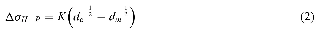
wheredmanddcare the averageα-Mg particle size of BM alloy and composite,respectively,andKis the Hall-Petch coefficien of the Mg matrix.
The large discrepancy in the coefficien of thermal expansion (CTE) as well as elastic modulus between Mg and GNPs can induce the geometrically necessary dislocations (GNDs),which may contribute to the strength increment.The contribution of GNDs can be expressed as [45]:
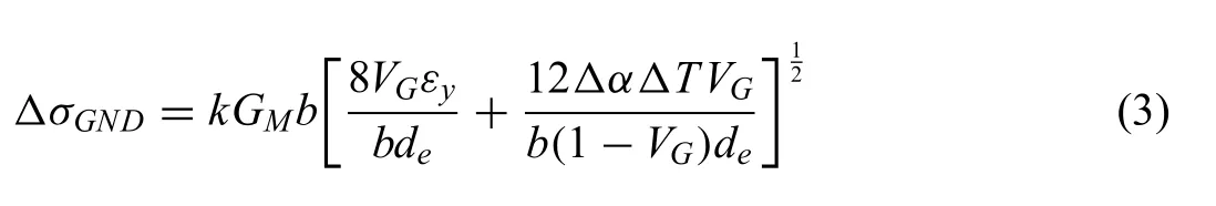
wherekis a constant,GMis the shear modulus of the matrix,bis the burgers vector of the matrix,Δαis the CTE mismatch between GNPs and Mg matrix,εyis the yield strain (0.2%),ΔTis the difference between the thixoforging and test temperature.If one piece of GNPs is simplifie as a square plate with average thickness oftand length ofL,respectively,the effective particle diameter,de,is:
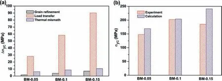
Fig.13.Theoretical calculation of the various strengthening mechanisms: (a) strengthening contribution;(b) comparison between calculated and experimental strength values.

Thus,taking the above two metallurgical factors into consideration,the yield strength of the composites (σyc) can be predicted using the modifie shear-lag model,which is given as [46,47]:

whereS=2(L+t)×Lis the interfacial area of GNPs,A=L×tis the cross-sectional area.The parameters needed for calculating the strengthening contributions are listed in Table 1.The predicted strength and experimental values of composites are given in Table 2 and also compared in Fig.13.Clearly,the calculated strength of 204MPa for BM-0.1GNPs is very close to its experimental value (202MPa),while the overestimated values relative to the experimental results are associated with both BM-0.05GNPs and BM-0.15GNPs.Two limitations will make the measured strength smaller than the predicted values.Firstly,GNPs are randomly oriented and agglomerated at high content rather than well aligned with the load direction and ideally dispersed in the matrix as assumed in the shear-lag model.Second,the average size of GNPs used for prediction is only a rough estimate from SEM observations but the actual size distribute widely,which leads to the inaccuracy of the predicted values.For the BM-0.1GNPs,the refinin effect of GNPs on the secondary eutectics should be more significan due to the optimal GNPs content,which may contribute more to the increased strength,accounting for the good agreement of the predicted strength with the measured value.Besides,Fig.13(a) suggests that the dominant strengthening effect is from load transfer while the grain refin ing and GNDs strengthening contribute insignifican enhancement.Therefore,the load transfer should be regarded as the major strengthening mechanism in the present composites.
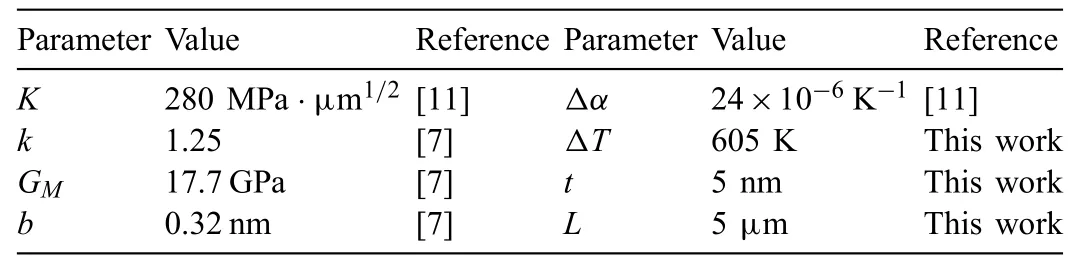
Table 1 Parameters needed for calculating strengthening contributions.

Table 2 The calculated strength increments of the composites.
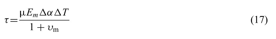
For a given thickness oft,the load transfer effect is highly dependent upon the length of GNPs.According to the shearlag model based on the fibe reinforced MMCs [36,48],the response of GNPs length to the load transfer effect can be predicted by introducing GNPs size parameters and critical length (Lcr).Upon the applied load,if the actual length of GNPs is larger than the critical length (L >Lcr),the stress on the GNPs is linearly increased from zero at its ends to the tensile strength of GNPs at its mid-point.Thus,GNPs fracture will occur and the strengthening effect of GNPs is more efficient whereas forL Based on a simple force balance on one piece of GNPs,Lcrcan be define as: Thus,the fracture strengthσc(UTS) of composite can be expressed as follows [48]: Fig.14.Effects of GNPs failure mode on strengthening efficien y (R) as functions of (a) GNPs length (L) and (b) interfacial bonding (τ) based on the shear-lag model. whereτis interfacial shear stress,σmis the UTS of matrix (251MPa),σGis the tensile strength of GNPs,namely 30GPa [23].Givenτis equal to its up-limitτm(i.e.,the shear strength of the matrix,∼67MPa for BM alloy),Lcris calculated as 2.25μm from Eq.(6).Since the actual lateral size of GNPs ranges widely from 1μm to 7μm and covers the calculatedLcr,a possible combination of GNPs fracture mode and GNPs pull-out mode might take effect.Thereby,both the strength and toughness are increased simultaneously by GNPs. Based on Eq.(1),the strengthening efficien y corresponding toσccan be written as: According to Eqs.(7) – (9),Rcorresponding toLcan be expressed as: Fig.14(a) depicts theRobtained from Eqs.(10) and (11).Apparently,the longer the GNPs are,the larger theRvalue is.Long GNPs can activate the GNPs fracture mode,therefore being more helpful to the effective load transfer than short GNPs. Considering the relation between the GNPs failure behavior and interfacial strength (τ),one piece of GNPs with a specifi length (L) will be broken ifτis larger than a critical interfacial shear stress (τcr),which can be derived from Eq.(6) and expressed as: wheres=is the aspect ratio of GNPs.Otherwise,GNPs will be pulled out from the matrix. Combining Eq.(6),Eq.(10)and Eq.(11),Rcorresponding toτcan be deduced to be: As shown in Fig.14(b),theRobtained from Eqs.(13) and(14) is also in proportion toτ,and the maximumR(Rmax) is attained whenτreaches to its maximum value (τm).The result indicates that strong interfacial bonding can operate the GNPs fracture mode,corresponding to a higherR.Since the pull-out of GNPs caused by weak interfacial bonding is related to a lowerR,it is unfavorable for the load transfer efficien y. In fibe or CNTs reinforced ceramic composites,the toughening has been considered to derive mainly from the extrinsic mechanisms including crack deflectio and GNPs bridging.The former is mostly governed by the shape of reinforcing phase,while the latter benefit from the reinforcement strength and the interfacial bonding [49,50].Likewise,for GNPs-reinforced composites,the unique 2D geometry with large aspect ratio of GNPs is expected to be highly effective in toughening composites through inducing crack evolution and interfacial interactions toward great energy absorption during crack propagation [51]. To reveal the possible extrinsic toughening mechanisms,in-situ tensile SEM observations were carried out.Figs.15 and 16 present the in-situ SEM images of the BM alloy and BM-0.1GNPs,respectively.In the matrix alloy,the major crack propagated along a relatively straight path,neither clear deflection nor small secondary cracks appeared.In comparison,the primary crack in the composite propagated tortuously and was deflecte obviously (Fig.16(a-c)).Under the exerted load,several secondary cracks were stimulated and propagated near the primary crack (Fig.16(c)).The crack deflectio and the secondary cracks were induced by the interfacial mismatch between matrix and GNPs typically accompanied with the interfacial debonding [51],which can elongate the crack length,enlarging the fracture energy absorption.The energy required to propagate crack (Ws) correlates with the crack length by [49]: Fig.15.In-situ SEM images of BM alloy.The dash line indicates the joint position between the two consecutive observing stages. whereλis the crack length,δis the out-of-plane thickness of solid material,andγis the sum of surface energy (γs)and plastic deformation energy (γp).The crack length in Fig.15(b) was measured by pixels as ∼260μm,while the total crack length in Fig.16(b) was ∼352μm.This indicated that the toughness of composite was higher than that of the matrix alloy. Moreover,crack propagation can be impeded by GNPs pull-out process,which is the so-called "bridge-toughening effect" [52].The bridging effect of GNPs was also confirme by the experimentally observed GNPs pull-out and GNPs rupture phenomena.As seen in Fig.16(d),the GNPs with sharp jagged edge (marked with dotted circle) gave the evidence that GNPs had broken into two parts,while those with smooth edge (marked with arrows) similar to that of original GNPs were related to GNPs pull-out rather than breaking.This observation was also consistent with the GNPs failure mode judged byLcr,confirmin an achievement of both strengthening and toughening effects in the present composite.As shown in Fig.16(e) and (f),the exposed GNPs on the fracture surface of composite clearly demonstrated that some GNPs were pulled out from Mg matrix and straightened along the load direction (Fig.16(f)).It is considered that this stretching and pull-out process can enhance the matrix-GNP interactions and dissipate more fracture energy via interfacial debonding and subsequent friction,contributing to the toughness enhancement [53,54]. It is hard to measure experimentally the toughness contribution from GNPs bridging.On the other hand,due to the random orientation of GNPs with unique 2D geometry,the developed theoretical models for cylindrical fiber aligned normal to the crack plane may be not applicable in this case.Therefore,we attempt to propose a suitable model for randomly oriented GNPs with 2D geometry to theoretically evaluate the toughening effect of GNPs bridging.As schematically illustrated in Fig.17,when one single piece of GNPs is pulled out from matrix at an angle to the pull-out load direction,certain assumptions are required: i) there exists a constant frictional shear stress at matrix/GNP interface;ii) GNPs and matrix are only frictionally bonded and only the interfacial friction contributes to the increase in pull-out energy.Thus,based on the proposed model [55] for randomly orientated short fiber in ceramics,and taking into account the 2D geometry and orientations of GNPs,the energy required to pull-out one single piece of GNPs can be expressed as: wherelis the embedded length of GNPs in the matrix,φdesignates the orientation angle of GNPs with normal to the crack plane,μis a coefficien of interfacial friction between GNPs and matrix.The interfacial shear stressτcan be estimated by [56]: Fig.16.(a)-(c) in-situ SEM images of BM-0.1GNPs composite: (d) the magnifie image of marked region in (b);(e) the exposed GNPs on the fracture surface;(f) the magnifie image of marked region in (e).The dash line indicates the joint position between the two consecutive observing stages. whereEmis Young’s modulus of the matrix (45GPa for the BM alloy),υmis Poisson’s ratio of the matrix (0.35 for Mg),ΔαandΔTare the same as define earlier. Thus,the total pull-out contribution to the composite fracture energy can be modelled as [55]: wherezdenotes the distance of the centroid of GNPs from crack plane,and the other related functions are define as follows: Fig.17.The model for pull-out of GNPs with the length L and the embedded length l,oriented at an angle φ to the loading axis. Note that the functionU(g) in Eq.(18) is used to discount those GNPs which will be broken instead of pull-out due to imperfect interfacial bonding,and the parameterβin Eq.(22) is an artificiall chosen large positive number depending upon the any desired accuracy of approximation[57].Based on the above formulas,the fracture energy (G) of the composite due to GNPs pull-out can be rewritten as: Numerical calculations were conducted using Matlab according to Eq.(25),and the influence of the involved parameters on the fracture toughness were examined.Fig.18(a)describes the fracture energy(G)as a function of GNPs length(L).There is a modelled critical length of GNPs (Lcr-m) analogous toLcrdefine in the shear-lag model,at which the maximum fracture energy (Gmax) is attained.Moreover,at a given GNPs content,ifL Moreover,the toughness contribution from GNPs bridging is sensitive to the friction coefficien of interface (μ).For short GNPs (L Furthermore,Fig.18(c)indicates that the increase of GNPs content can enhance the fracture toughness of composite.Surprisingly,as described in Fig.10(c),a relatively high content(0.15wt.%) of GNPs led to a decrease in the measured toughness.In the present model,the dispersion degradation caused by increased GNPs content has not been considered.Poor dispersion of GNPs will induce the formation of pores and thus cause local stress concentration,making crack propagate more quickly.Therefore,just like strengthening,only the better dispersion of GNPs can realize the potential of toughening effect. It should be pointed out that the present model is also applicable to chemically-bonded interfaces.Introducingμin this model is only to evaluate the interfacial bonding strength.Replacingτin Eq.(17) by a given interfacial shear stress,the toughening contribution of GNPs pull-out in terms of chemically-bonded interface can be modelled. GNPs reinforced ZK60 matrix composites were fabricated by powder thixoforging combined with a wet mixing process.Based on the experimental and theoretically analytical results,the main conclusions can be drawn as follows: (1) The ball-milled powder was beneficia for a homogeneous distribution of GNPs and a denser microstructure with reduced eutectics as compared to the non-milled powder,which resulted in 52% increment in yield tensile strength and 19% enhancement in toughness for the BM-0.1GNPs compared with the BM alloy.The as-thixoforged composite was endowed with acceptable mechanical properties and high strengthening efficien y without additional deformation,demonstrating that the combination of GNPs and powder thixoforging has considerable potential in mass-producing novel MMCs. (2) GNPs were distributed alongα-Mg PBs.The thixoforging process was enough to promote a well-bonded Mg/GNP interface,which could provide a significan load transfer effect of GNPs,so a pronounced strengthening efficien y of 650% was achieved in the BM-0.1GNPs composite. (3) Theoretical analysis suggested that load transfer was the main strengthening mechanism,the grain refinin and GNDs strengthening contributed a little to the strengthening effect. (4) Crack deflectio and secondary cracks induced by GNPs and the bridging effect of GNPs mainly accounted for the toughening mechanisms.A suitable model for randomly oriented GNPs with 2D geometry was proposed to evaluate the toughening effect of GNPs bridging.The modelled results showed that the toughness contribution from GNPs bridging was dependent on both GNPs length and interfacial bonding between matrix and GNPs,and a good match between GNPs length and interface bonding strength can achieve the enhanced strength and toughness simultaneously. Declaration of Competing Interest None. Acknowledgments This work was financiall supported by the National natural Science Foundation of China (Grant No.51761028).


3.6.Toughening mechanisms


4.Conclusions
杂志排行

Journal of Magnesium and Alloys的其它文章
- Effect of crystallization on purity of volatile metallic magnesium prepared from a one-step multi-region condensation process under vacuum condition
- Tribological behaviour of AZ31 magnesium alloy reinforced by bimodal size B4C after precipitation hardening
- Thermodynamic assessment of Mg−Ni−Y system focusing on long-period stacking ordered phases in the Mg-rich corner
- Primary Mg2Si phase and Mg2Si/α-Mg interface modifie by Sn and Sb elements in a Mg-5Sn-2Si-1.5Al-1Zn-0.8Sb alloy
- Quasi-in vivo corrosion behavior of AZ31B Mg alloy with hybrid MWCNTs-PEO/PCL based coatings
- The microstructure evolution and deformation mechanism in a casting AM80 magnesium alloy under ultra-high strain rate loading