Differences in MBUs induced by high-energy and medium-energy heavy ions in 28 nm FPGAs
2022-11-21ShuaiGaoJinHuYangBingYeChangCaiZeHeJieLiuTianQiLiuXiaoYuYanYouMeiSunGuoQingXiao
Shuai Gao• Jin-Hu Yang • Bing Ye• Chang Cai• Ze He•Jie Liu • Tian-Qi Liu • Xiao-Yu Yan • You-Mei Sun • Guo-Qing Xiao
Abstract Multiple-bit upsets (MBUs) have become a threat to modern advanced field-programmable gate arrays(FPGAs) applications in radiation environments. Hence,many investigations have been conducted using mediumenergy heavy ions to study the effects of MBU radiation.However, high-energy heavy ions (HEHIs) greatly affect the size and percentage of MBUs because their ionizationtrack structures differ from those of medium-energy heavy ions.In this study,the different impacts of high-energy and medium-energy heavy ions on MBUs in 28 nm FPGAs as well as their mechanisms are thoroughly investigated.With the Geant4 calculation, more serious energy effects of HEHIs on MBU scales were successfully demonstrated. In addition, we identified worse MBU responses resulting from lowered voltages. The MBU orientation effect was observed in the radiation of different dimensions. The broadened ionization tracks for tilted tests in different dimensions could result in different MBU sizes.The results also revealed that the ionization tracks of tilted HEHIs have more severe impacts on the MBU scales than mediumenergy heavy ions with much higher linear energy transfer.Therefore, comprehensive radiation with HEHIs is indispensable for effective hardened designs to apply highdensity 28 nm FPGAs in deep space exploration.
Keywords FPGA ∙High-energy heavy-ion radiation ∙MBU ∙Ionization track
1 Introduction
The high performance and flexible configuration ability of static random-access memory (SRAM)-based field-programmable gate arrays(FPGAs)make them widely used in space missions[1–4].However,they are sensitive to single event upsets (SEUs) caused by heavy-ion incidence [5–7].Moreover,as feature sizes continuously shrink,the reduced critical charge and enhanced charge sharing effect in FPGAs lead to multiple-bit upsets(MBUs)occurring more frequently [8, 9]. MBUs occur when single particles deposit energy into several memory cells of the same words to simultaneously upset them.When MBUs occur in critical configuration RAMs (CRAMs) that are used to configure critical system functions,on-orbit FPGA systems face serious failures [10,11].Therefore,it is mandatory to conduct an MBU evaluation of CRAMs on advanced FPGAs before their application in aerospace.
Since 28 nm FPGAs possess economical applicability and excellent compatibility with peripheral devices, the impact of medium-energy heavy ions on their MBUs has been widely studied [12–14]. Except for vertical radiation tests, previous FPGA-based works have shown that MBUs greatly depend on the device orientation relative to the heavy-ion beam directions [15, 16], that is, tilted heavy ions could affect more cells to generate larger-scale MBUs.In addition, the voltage of the device is an essential factor that influences the MBU responses in FPGA radiation experiments [17, 18]. This is because, as the voltage decreases,the critical charge of the transistors also reduces,and they may be more easily upset, causing larger MBUs.Tests at normal incidence and voltage will not capture the worst MBU responses and finally affect the targeted hardening designs. Thus, radiation tests on FPGAs should consider critical conditions to predict radiation sensitivities more accurately. However, detailed MBU data for the comprehensive parameters of 28 nm FPGAs have not yet been presented. Furthermore, it is important to study internal physical mechanisms.
In addition to medium-energy heavy ions, high-energy heavy ions (HEHIs) existing in deep space have prompted researchers to perform related radiation tests [19]. For HEHIs with linear energy transfer (LET) near or less than the threshold of given devices, previous works presented higher MBU cross sections resulting from the nuclear interaction products of the HEHIs [20, 21], implying that the energy of heavy ions is becoming an important factor affecting the MBU evaluation of critical devices. In addition,Du et al.revealed that compared with medium-energy heavy ions, HEHIs with even lower LET can induce more severe MBUs [22]. HEHIs may lead to more complex MBU features and significantly affect the logic states of the FPGAs.However,the probability of nuclear interactions is sufficiently low [23, 24]. Moreover, for HEHIs with very low LET, although they have wide ionization tracks in the direct ionization process, the relatively low electron–hole pairs generated inside hardly induce upsets [25]. When HEHIs reach a higher LET,the combined influences of the wide track and high LET could have a higher probability of creating larger-scale MBUs and further cause abnormalities in FPGAs. These large MBUs are more difficult to correct using error-correcting methods [26, 27]. Unfortunately, no such high-energy investigations have been presented to more accurately characterize the impacts of HEHIs with high LET on representative 28 nm FPGAs as well as reveal the mechanisms behind the observed results.Furthermore, these results and mechanisms would significantly affect the process of new hardened designs and the security of deep space exploration.
In this study, we conducted high-energy and mediumenergy heavy ion tests on 28 nm FPGAs. The effects of heavy ions with different energies on the MBUs were thoroughly investigated. The Geant4 calculation results successfully identified worse MBUs induced by HEHIs.We also studied more serious MBU responses resulting from lowered voltages. In addition, the MBU orientation effect was confirmed in different dimensional radiation tests. The sizes and shapes of the MBUs changed with the different device orientations. The broadened ionization tracks in these orientations can significantly influence the MBU sizes. The remainder of this paper is organized as follows. Section 2 describes the devices, our test system,and experiments. The results for the HEHIs and mediumenergy heavy ions are presented in Sect. 3. Section 4 illustrates a detailed MBU analysis and discussion.Finally,we present our conclusions.
2 Experimental setup
2.1 Devices under test and test system
The 28 nm Kintex-7 FPGAs from Xilinx were chosen as the devices under test (DUTs). The Kintex-7 family of FPGAs offers substantial programmable logical configuration resources (that is, CRAMs). The Xilinx 7 series devices operate on the VCCINT power supply rail,and the voltage ranges from a minimum of 0.9 V to a maximum of 1.0 V.To meet the range requirement of the radiation tests,the substrate was thinned to approximately 50 μm.
To better characterize the various test vectors in radiation experiments, a test board was developed, and the diagram is illustrated in Fig. 1. The entire test system consists mainly of the motherboard and daughterboard.A Kintex-7 FPGA obtained from Xilinx was selected and placed in the motherboard to control the configuration,readback, and comparison of the DUT configuration. The bitstream used to configure the DUT is stored in an external flash. CRAM can be characterized in static or dynamic modes. The control modules help to read the bitstream back. The error comparison between the radiation and golden bitstreams is performed in the XC7K325T chip. In addition, during the radiation tests, the error data and information were transmitted to a personal computer through an RS 232/485 converter.The separate structure of the test system makes it possible to perform arbitrary hardware designs to satisfy diverse testing requirements.
The monitor modules were designed to read and record both the voltage and current information of the DUT during the radiation tests. The power modules are responsible for powering the entire test system and maintaining a stable voltage.In addition,a C#-based customized software with a visual interface was designed to make the control and data analysis more accurate and convenient. This allowed for the observation and recording of the radiation data in real time. During the experiment, the computer placed in the test room was connected to our test board to control the test system by operating the software.
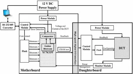
Fig.1 Diagram of the radiation test system
2.2 Experimental information
High-energy78Kr and medium-energy129Xe heavy ion experiments were performed at the Heavy Ion Research Facility in Lanzhou (HIRFL) at the Institute of Modern Physics, Chinese Academy of Sciences. Irradiation tests were conducted in air and at a nominal temperature. The78Kr and129Xe ions with initial energy of 60 and 19.5 MeV/u were provided by high-energy radiation effect(HERE) terminal and terminal No.5 (TR5), respectively.For tests at TR5, the devices must be thinned down to ensure that heavy ions reach the sensitive region inside the DUT. For high-energy tests, the HERE terminal in HIRFL can accelerate heavy ions to hundreds of MeV per atomic mass unit,which provides a wide energy spectrum for SEU investigations. In addition, the heavy ions provided by the HERE terminal have a very long range.Thus,the prototype devices can be easily evaluated without pre-thinning or decapping.
In the experiments, aluminum degraders of different thicknesses were added in front of the DUT to obtain several appropriate LETs. The DUT radiated in TR5 was fixed on a 5-dimensional platform to change the positions in three directions and to rotate at two angles (azimuth θ and zenith ψ), as shown in Fig. 2. Static modes were employed in both the high-energy and medium-energy tests. This prevents unexpected errors, such as burst errors during reconfiguration. Table 1 lists the detailed information used in the experiments. Multiple tilts and voltages were coupled to explore the radiation sensitivities of the DUT, which were helpful in obtaining the worst MBU responses. Prior to the tests, a specific circuit was configured by loading a known bitstream into the CRAM. After each trial, the configuration bits were read back via the SelectMAP interface and compared with the golden bitstreams to distinguish the upsets. Finally, log files with the number of errors and logical locations were generated to identify the MBU patterns.

Fig.2 (Color online)Diagram of the radiation angles:azimuth θ and zenith ψ
3 Results
3.1 HEHI tests
Figure 3 graphs the cross sections of HEHI tests under different coupling parameters. For three LETs, the cross sections exhibited good consistency. Under all conditions,0.9 V tests had higher cross sections than those of 1.0 V.This is because heavy-ion tracks in the physical layout can cover more 0.9 V cells than 1.0 V to create larger sizes and higher percentages of MBUs. The increased cross sections from 1.0 to 0.9 V proved that the critical charge reduction caused by the decreased voltages requires close attention from SEU evaluators. Furthermore, the large tiltdependence of the SEU cross sections was identified.Compared with voltage, the influence of tilt was remarkably obvious, which is critical for the MBU evaluation of FPGAs. The maximum discrepancy in cross sections induced by tilted radiation can reach approximately 43.8%,revealing that when HEHIs with a higher LET are tilted incident into FPGAs, more cells would be affected to create more MBUs.Furthermore,compared with incidence under the vertical condition,the sharp increase of the cross section under the(0°,30°)condition from the LET of 20.8 to 31.0 MeV/(mg/cm2) indicated that78Kr ions with stronger ionization ability can cause more serious MBUs.In actual space, these MBUs would significantly threaten the reliability of FPGA-based on-orbit systems, which is important in radiation evaluations. When the combined effect of both the angle and bias is considered and the LET is equal to 31.0 MeV/(mg/cm2), the discrepancy reached 46.2%, as shown in Fig. 3 (the difference between the red dot and blue triangle). Additionally, since the actual space environment has worse conditions, the coupled parameters are extremely necessary during radiation evaluation to prevent the overestimation of SEU tolerance.
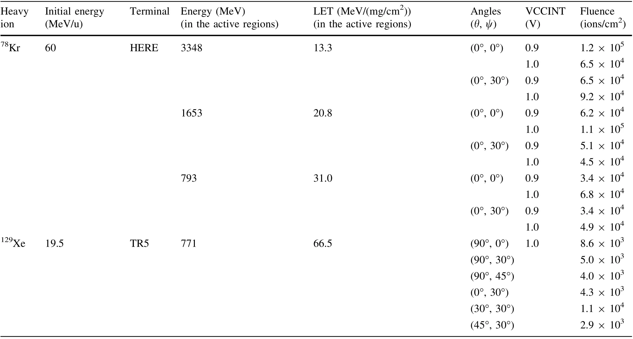
Table 1 Experimental information of radiation tests

Fig. 3 Cross sections of CRAM vs. LET under different angles and voltages
3.2 Medium-energy heavy ion tests
The cross sections of the CRAM irradiated by129Xe ions, shown in Fig. 4, demonstrated good consistency as a function of the angles. Additionally, the upsets exhibited different dimensional dependences. In particular, the cross section of (0°, 30°) was higher than that of (90°, 30°).During the analysis, we found that, for the vertical radiation condition, upsets mainly occurred along the word direction rather than between words. Furthermore, larger MBUs appeared when performing the (0°, 30°) tests.However, in the (90°, 30°) and (90°, 45°) conditions,multiple events occurred mainly between adjacent words.The above results confirmed the shorter distances between two adjacent cells along the word direction.Furthermore,it revealed that the different physical distances between sensitive nodes in different directions significantly affect the device sensitivity. For the DUT used in this study, the closer distance between cells in the word direction should be given special attention by radiation evaluators. In addition, radiations under ψ = 30° had more serious impacts on the FPGA function, with a maximum of approximately 1.7 × increment from (90°, 0°) to (45°,30°).

Fig. 4 Total CRAM SEU cross sections induced by 129Xe ions at different tilts
4 MBU analysis and discussion
As mentioned earlier, different MBU responses existed when radiation experiments were performed with different voltages and tilts. The MBU results revealed the effects of lowered voltage, ionization trajectories, and track structures of heavy ions on our 28 nm FPGAs. Owing to the advanced test platform,the analysis of MBUs can be easily performed according to the log file comparison.
4.1 MBU results of HEHIs
Table 2 shows the percentages of SBUs, 2-bit MBUs,and greater-than-2-bit MBUs under all experimental conditions. When the LET was 13.3 MeV/(mg/cm2), as the small LET of HEHIs, the influence of the angle on the percentage of MBUs was not obvious. However, as the LET increased,the tilt-induced percentages of 2-bit MBUs significantly increased, which explains the sharp increase observed in Fig. 3.Owing to the decreased critical charge,more MBUs appeared during the 0.9 V operation.
To further reveal the influence of tilt and voltage on the scales and percentages of MBUs, detailed information of greater-than-2-bit MBUs was extracted,as shown in Fig. 5.As mentioned in Sect. 3.1, the 0.9 V radiations induced higher cross sections. Although the increase was small,they had a greater influence on the MBU sizes. Compared with the 1.0 V, the 0.9 V radiations induced a higher proportion of and larger-scale MBUs.At normal incidence of 13.3 MeV/(mg/cm2), due to the small LET of HEHIs,only 0.9 V radiations induced 5-bit MBUs, whereas 1.0 V radiations did not. When the LET was 31.0 MeV/(mg/cm2),the(0°,30°)condition tilted78Kr ions induced larger 6-bit MBUs in the 0.9 V DUT than in the 1.0 V, which is the same as the normal incidence of78Kr ions with 13.3 MeV/(mg/cm2). We speculated that this is because these two heavy ions with different energies have different ionization-track structures. In tilted radiation, the lowered 0.9 voltage compared to 1.0 can produce more MBUs.Additionally, we found that compared with 13.3 and 31.0 MeV/(mg/cm2),78Kr ions with an LET of 20.8 MeV/(mg/cm2) can cause higher percentages of greater-than-3-bit MBUs in vertical radiations at 0.9 and 1.0 V, and greater-than-4-bit MBUs in tilted radiations at the 0.9 V operation. This is related to the different influence ranges and abilities of the ionization tracks.
Because the (0°, 30°) ion trajectories covered more cells, the largest 6-bit MBUs appeared even at the LET of 13.3 MeV/(mg/cm2), which identified the worst influences in this study. Compared with the LET impact, the tilt played a more important role in the generation of larger MBUs and high percentages of greater-than-3-bit MBUs,which can be determined from the comparison both between 0.9 V-13.3 MeV/(mg/cm2)-(0°, 30°) and 0.9 V-31.0 MeV/(mg/cm2)-(0°, 0°), and 1.0 V-13.3 MeV/(mg/cm2)-(0°,30°)and 1.0 V-31.0 MeV/(mg/cm2)-(0°,0°).The maximum 6-bit MBUs all appeared under the condition of(0°, 30°) incidence. The more severe impacts of the ion trajectories revealed that the tilted78Kr ions had a wider track influence range on the layout of the DUT.
In the comparison of two different voltage radiations,at LET equal to 31.0 MeV/(mg/cm2), the increased 2-bit MBUs appeared to cause the roll-up in the overall MBU percentages. However, under the low LET conditions of 13.3 and 20.8 MeV/(mg/cm2), the higher percentages of MBUs at 0.9 V were mainly due to the generation of greater-than-2-bit MBUs whether at normal or tilted incidence.These results indicated that different track structures of heavy ions with different energies can induce different MBU types.For all the results illustrated in this subsection,the reduced voltages and tilted HEHIs showed worse MBU effects, which clearly demonstrated that the characterization of large-scale MBUs caused by worst parameters is indispensable in radiation evaluations.
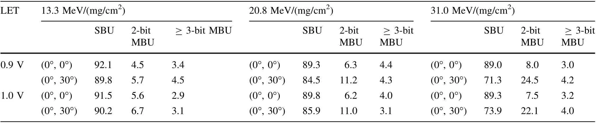
Table 2 Percentages of SBUs, 2-bit and greater-than-2-bit MBUs at different radiation parameters

Fig. 5 (Color online) Detailed percentages of greater-than-2-bit MBUs of different types at different conditions
4.2 MBU results of 129Xe ions
Figure 6 shows the percentages of SBUs, 2-bit MBUs,and greater-than-2-bit MBUs caused by129Xe ions at various tilts. With increasing tilt, the percentage of MBUs also increased. More MBUs appeared at (0°, 30°) than at(90°, 30°); that is, more obvious dimensional dependence was identified. The significant MBU orientation effects implied that the incident directions of ions with respect to the layout of the cells are crucial.For the greater-than-2-bit MBUs, the maximum approximately 2.87 × increment between (90°, 0°) and (45°, 30°) made the functionality of our customized design abnormal.
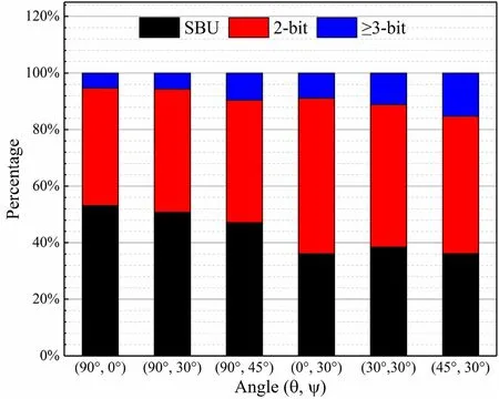
Fig.6 (Color online)Percentages of SBUs,2-bit,and greater-than-2-bit MBUs under different angles

Fig. 7 Detailed percentages of greater-than-2-bit MBUs at various tilts
To further reveal the effects of different dimensions on the MBU scales and percentages, the detailed results of greater-than-2-bit MBUs are shown in Fig. 7. Only the largest 3-bit MBUs were found at (90°, 0°). When setting θ = 90°while rotating ψ,we captured MBUs no larger than 4-bit; however, for ψ = 30° while changing θ, the largest 5-bit MBUs appeared six times,which helped us determine worse dimensional impacts.In addition,the percentages of 3-bit MBUs at(0°,30°)were approximately twice as large as those at (90°, 30°), further demonstrating that there are indeed different sensitivities in the directions of either the word or between words in our DUT. We observed that large-scale upsets occurred between words in our DUT at θ = 90°, but the largest number was four. When considering the largest 5-bit MBUs, we believed that the distances between word cells are closer than the cells between words.
4.3 Geant4 simulation
When comparing the MBU results between78Kr and129Xe ions,it was found that,although HEHIs have a much lower LET, they can induce even larger MBUs. This appears to be caused by the different ionization-track structures. Hence, using the Geant4 toolkit, we performed Monte Carlo simulations to investigate the track structures of the78Kr and129Xe ions used in our experiments. The results are shown in Fig. 8.It can be seen that HEHIs have much wider tracks;particularly,the78Kr ions of 3348 MeV are approximately five times wider than the129Xe ions.Large clustered MBUs occurred due to their large track radius. However, owing to their relatively low density of electron–hole pairs inside tracks, the largest 6-bit MBUs appeared only under the(0°,30°)tests.The tilted incidence would cause a widened track to affect more cells, indicating that the larger track area of HEHIs is more catastrophic in the generation of larger MBUs than129Xe ions with a much higher LET.

Fig. 8 Electron–hole pairs density changing as a function of the radial distance in silicon
As mentioned in Sect. 4.1, we found that the78Kr ions of 1653 MeV had a more serious impact on the MBU percentages.Figure 8 displays these results well.Although the78Kr ions of 1653 MeV have a similar ionization radius to those of 3348 MeV, they generated more electron–hole pairs during their interaction with transistors, leading to a higher probability of MBUs. In addition, in contrast to the78Kr ions with 793 MeV, although the78Kr ions of 1653 MeV have smaller electron–hole pair densities along their trajectories, their wider ionization tracks could result in more sensitive drains of transistors collecting charges to be probabilistically upset. That is, as the78Kr ions with an energy of 1653 MeV have a better trade-off between the wide ionization track radius and electron–hole pair density,more MBUs occurred.
In addition,the track structures well explained the highenergy results observed in the experiments.When the LET was relatively small (that is, 13.26 and 20.83 MeV/(mg/cm2)), the 0.9 V radiations induced mainly larger-scale MBUs than at 1.0 V; whereas at 31.04 MeV/(mg/cm2),HEHIs caused more 2-bit MBUs. For the almost equal ion track radius of HEHIs of 1653 and 3348 MeV,as78Kr ions with lower energy can deposit energy in more cells, more 0.9 V transistors may be upset at the edge of the track that exceeds the critical charge of the 28 nm FPGA cells.Thus,the generation of greater-than-2-bit MBUs led to an increase in the overall MBU ratio. However, despite the higher density of ionized charge at the center of the track for78Kr ions of 793 MeV, the narrower track made the 2-bit MBUs responsible for the increased percentage of MBUs induced by 0.9 V.
The heavy-ion-induced ionization track is shaped like a cylinder and can be up to several microns in diameter in silicon. However, tracks may sometimes be deformed depending on the selection of experimental parameters,such as angles. A diagram of the relationship between the ionization tracks and memory cells is shown in Fig. 9. In nanoscale devices, the heavy-ion track usually covers several memory cells. For heavy ions with a given energy,the vertical view of the ionization track structure is roughly circular; however, when conducting tilted radiation tests,the track changes to an ellipse, as illustrated in Fig. 9(b).Taking the MBU orientation differences in the sensitivities observed in our radiation results as an example, the widened major axis of the elliptical track deposits energy in more cells. Although these cells collect relatively less charge than those closer to the center of the track, the collected charge may still cause upsets in modern advanced devices with small critical charges. Moreover, if the major axis of the ellipse is oriented in the word cells, as in our Kintex-7 FPGAs, then larger MBUs would appear, which are difficult to correct using error mitigation(such as errorcorrecting code). In both78Kr and129Xe ion radiation,because we performed two different dimensional tests, as shown in Fig. 9, we observed that the broadened track induced larger clustered events along and between words.Their orientations depended on the degree of θ used.In this study, radiation at θ = 0° can cause more and larger MBUs; therefore, the word direction of our DUT was confirmed.As θ = 90°orients the direction between words,the MBU percentages were almost equal for the three conditions we used in the129Xe ion tests. The widened tracks of HEHIs under tilted conditions significantly affect the MBU characterization in advanced integrated circuits.

Fig. 9 (Color online)Diagram of the relationship between heavy-ion tracks and memory cells for (a) vertical,and (b) tilted heavy-ion radiation
As advanced nanoscale commercial FPGAs have small critical charge, the wider tracks of HEHIs have worse effects than medium-energy heavy ions on large-scale MBUs. In particular, when performing tilted radiation, the reliability of the devices will be more seriously threatened.As essential factors in the actual space environment, more severe MBUs caused by the reduced voltage should also be carefully considered. The above results for both high-energy and medium-energy heavy ions showed that comprehensive considerations of actual space factors will be closer to the device evaluation requirements.Thus,to fully characterize the MBU features and ensure the successful implementation of effective MBU-hardened designs, it is necessary to take HEHIs and these comprehensive radiation conditions into account when designing ground-based accelerator tests.
5 Conclusion
This study highlighted and investigated the differences in MBUs induced by high-energy and medium-energy heavy ions in 28 nm FPGAs.Using the Geant4 simulation,we successfully identified the more serious effects of HEHI tracks on the MBUs.The track structures of the heavy ions with different energies used in this study were in good agreement with the radiation data. The results also proved that the wide ionization tracks of HEHIs at tilted radiations were more catastrophic in the generation of large-scale MBUs than the higher LET of medium-energy heavy ions.In addition, the larger scale and higher percentages of MBUs caused by the lowered voltage and tilted radiation were demonstrated. A large MBU orientation effect was observed, with most MBUs occurring at ψ = 30°. Especially in tilted tests, the widened major axis of the ionization track can cause more complex MBUs,which relied on whether the incident direction on the layout is in the word or between words. Therefore, to reduce the failure risk of FPGA-based systems in actual space, comprehensive high-energy characterizations are necessary to prevent the underestimation of radiation reliability.
SEU mitigation strategies depend on actual and accurate irradiation results. Therefore, radiation designers should carefully consider the comprehensive factors mentioned in this paper to prevent wastage of the area,resources,power,and operation frequency of devices.
Acknowledgments We thank the members of the HIRFL for providing the heavy-ion testing platform. We are also grateful to the FPGA development department of the Shanghai Fudan Microelectronics Group for their assistance with the test system.
Author contributions All authors contributed to the study conception and design. Material preparation, data collection and analysis were performed by Shuai Gao,Jin-Hu Yang,Bing Ye and ChangCai.The first draft of the manuscript was written by Shuai Gao, Jin-Hu Yang and Bing Ye, and all authors commented on previous versions of the manuscript. All authors read and approved the final manuscript.
杂志排行
Nuclear Science and Techniques的其它文章
- Hard X-ray focusing resolution and efficiency test with a thickness correction multilayer Laue lens
- Monte Carlo study of the neutron ambient dose equivalent at the heavy ion medical machine in Wuwei
- Experimental investigation on the characteristics of molten lead–bismuth non-eutectic alloy fragmentation in water
- Configurational information entropy analysis of fragment mass cross distributions to determine the neutron skin thickness of projectile nuclei
- Thin-film approximate point scattered function and its application to neutron radiography
- Mechanical properties and surface characteristics of SiC fibers irradiated by swift heavy ions