Effect of irradiation on temperature performance of dispersioncompensation no-core cascade optical-fiber sensor coated with polydimethylsiloxane film
2022-11-21FangWangQiuFengWuYuRongJiangChanJinXiaoHuiWangBenShangZhangChunWangMa
Fang Wang • Qiu-Feng Wu• Yu-Rong Jiang • Chan Jin • Xiao-Hui Wang •Ben-Shang Zhang • Chun-Wang Ma
Abstract A temperature measurement device can produce data deviations and can even be damaged in a high-dose radiation environment. To reduce the radiation damage to such a device and improve the temperature measurement accuracy in a radiation environment, a temperature sensor based on optical-fiber sensing technology is proposed.This sensor has a cascade structure composed of a single-mode fiber (SMF), a dispersion-compensation fiber (DCF), a nocore fiber(NCF),and another SMF(SDNS).The DCF and NCF are coated with a polydimethylsiloxane(PDMS)film,which is a heat-sensitive material with high thermal optical and thermal expansion coefficients.In experiments,PDMS was found to produce an irradiation crosslinking effect after irradiation, which improved the temperature sensitivity of the SDNS sensor. The experimental results showed that within a range of 30–100 °C, the maximum temperature sensitivity after irradiation was 62.86 pm/°C,and the maximum transmission sensitivity after irradiation was 3.353 × 10⁻² dB/°C, which were 1.22 times and 2.267 times the values before irradiation, respectively. In addition, repeated temperature experiments verified that the SDNS sensor coated with the PDMS film had excellent temperature repeatability. Furthermore, it was found that with an increase in the irradiation intensity, the irradiation crosslinking degree of PDMS increased, and the temperature sensitivity of the sensor was improved. The proposed sensor could potentially be applied to temperature measurement in a nuclear-radiation environment.
Keywords 60Co-γ irradiation ∙Optical-fiber sensor ∙Temperature performance ∙PDMS ∙Radiation crosslinking
1 Introduction
In nature, there are two common high-energy photon rays, namely X-rays and γ-rays [1, 2]. Although both are electromagnetic waves, γ-rays have shorter wavelengths,higher energy, and greater penetration power than X-rays.Therefore, people and electronic equipment exposed to γrays for a long period will suffer great harm [3]. At the same time, in special cases, it is necessary to measure the temperature in a nuclear radiation environment [4–6].However, the commonly used temperature measurement devices may be damaged or produce measurement errors in a high-dose radiation environment[7].Thus,a new type of optical-fiber temperature sensor was studied for use in a high-dose radiation environment. Optical-fiber sensors have the advantages of a small size,a compact structure,a simple manufacturing process,and an anti-electromagnetic interference characteristic, which makes it possible to use them for temperature measurement in radiation environments [8, 9].
Because of their different working principles, opticalfiber sensors with different structures have different temperature response characteristics in radiation environments[10–12]. In recent years, scholars have designed a variety of optical-fiber sensors and studied their temperature performances in radiation environments. Esposito et al.designed a pure silicon-core fluorine-doped clad fiber that had a temperature sensitivity of up to 22.8 pm/°C after irradiation [13]. Ju et al. prepared an optical-fiber sensing structure with a pure silicon glass buffer layer and borondoped silicon glass inner cladding for temperature measurement in a radiation environment. The temperature sensitivity of this sensor after irradiation reached 5.48 pm/°C in a temperature range of 18–40 °C [14]. Fiber Bragg gratings (FBGs) have also been used for temperature measurement in radiation environments. Ye et al. investigated the effect of60Co-γ irradiation on the Bragg wavelength shift (BWS) and thermo-optical response coefficient. The results showed that the BWS was linearly related to the temperature,with a temperature sensitivity of 10.1–24.0 pm/°C in a temperature range of 0–60 °C [15].The above-mentioned optical-fiber sensors could effectively be applied to temperature measurement in a radiation environment and had strong anti-electromagnetic interference capabilities. However, their low-temperature sensitivities and narrow temperature measurement ranges cannot be ignored.
The temperature sensitivity of an optical-fiber sensor can be improved by coating the surface of the sensing structure with a temperature-sensitive material [16]. The most commonly used temperature-sensitive materials include polydimethylsiloxane (PDMS), polyimide, and graphene and its composites.PDMS is a polymer with high thermal optical and thermal expansion coefficients[17–19].A series of chemical changes will occur in the polymer after high-dose irradiation. The main change is the crosslinking of the polymer molecular chain,which results in a radiation crosslinking effect and improves the thermal stability of PDMS [20–22]. As a consequence of the radiation crosslinking effect, the mechanical properties, heat resistance, chemical corrosion resistance, and aging resistance of polymer materials will also be improved [23].Because of its advantages, including a lack of toxicity, a soft texture,and easy preparation,PDMS is the best choice for coating materials.
To improve the temperature sensitivity of an opticalfiber sensor in a radiation environment, this article proposes an optical-fiber temperature sensor coated with a PDMS film. The irradiation mechanism of the polymer could be understood by observing the morphology changes in the PDMS coating on the surface of the sensor after irradiation. This sensor was composed of a single-mode fiber (SMF), a dispersion-compensation fiber (DCF), a nocore fiber (NCF), and another SMF in sequence (SDNS).The temperature and transmission sensitivities of the SDNS sensor coated with the PDMS film before and after irradiation were numerically analyzed. At the same time, the reproducibility of the temperature measurement in an irradiated environment was investigated through repeated temperature experiments. This article is structured as follows. The fabrication of the sensing structure, sensing principle, simulation analysis, and irradiation mechanism analysis of PDMS are introduced in Sect. 2. The experimental steps, including the irradiation experiments and temperature measurement experiments, are described in Sect. 3.An analysis of the experimental results is presented in Sect. 4, and the conclusions of this article are summarized in Sect. 5.
2 Materials and methods
2.1 Fabrication of the sensing structure
Figure 1a shows a schematic of the SDNS sensor coated with the PDMS film. The SDNS sensor was mainly composed of DCF (the core/cladding diameters were 5/110 μm) and NCF (the cladding diameter was 125 μm)cascaded between the lead-in SMF and lead-out SMF (the core/cladding diameters were 8.2/125 μm).Meanwhile,the DCF and NCF were coated with a PDMS film. Figure 1b and c shows images of the splicing points for the SMF and DCF, and the DCF and NCF, respectively, which were taken using an optical microscope. It can be seen that the diameter of the outer layer of the SMF and NCF was approximately 125 μm, and that of the DCF was approximately 110 μm. In addition, an optical microscope image of the SDNS sensor coated with PDMS is shown in Fig. 1d.
To obtain better interference spectra,different structures and lengths of fibers were tested. As shown in Fig. 2a, the transmission spectra of SMF + NCF (2 mm) + SMF and SMF + DCF (4 mm) + SMF had no obvious interference peaks, while SMF + DCF + NCF + SMF did have interference peaks. As the DCF length increased, the number of interference peaks gradually increased, and the free spectral range (FSR) of adjacent interference peaks decreased. When the DCF length was set to 8 mm, the maximum extinction ratio (ER) could reach 20.61 dB. In addition,the spatial-spectral response was obtained using a fast Fourier transform (FFT). As shown in Fig. 2b, the FFTs of three DCFs of different lengths were analyzed. In the spatial spectrum, the peak intensity at zero was mainly related to the core mode. In addition, there was a major frequency component in the Fourier spectrum. The peak intensity of this frequency component was the largest when the lengths of the DCF and NCF were 8 mm and 2 mm,respectively. Therefore, SMF + DCF (8 mm) + NCF(2 mm) + SMF was finally selected for the experiment.
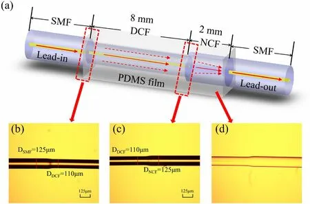
Fig. 1 (Color online)a Schematic diagram of the SDNS sensor coated with PDMS film. b SMF and DCF splicing point seen under an optical microscope. c DCF and NCF splicing point seen under an optical microscope. d Sensor seen under an optical microscope after coating with PDMS
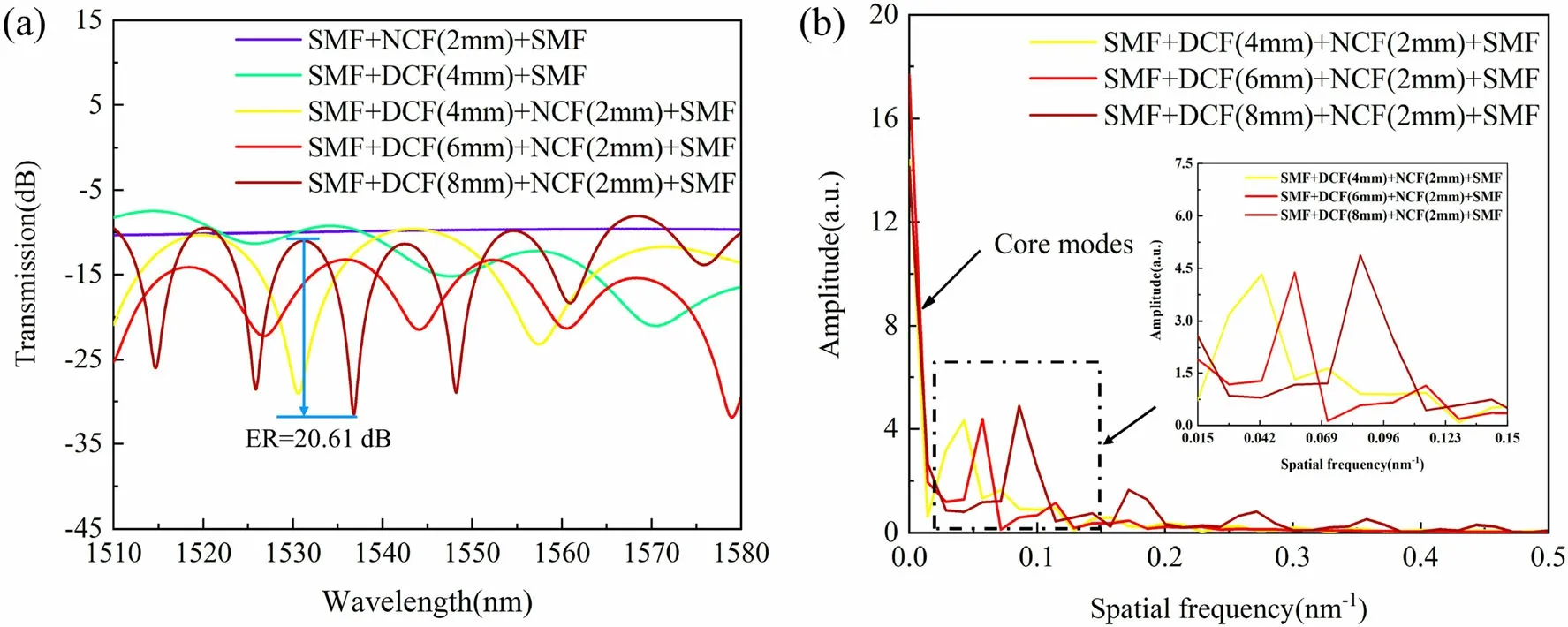
Fig. 2 (Color online) a Transmission spectra of different fiber structures. b FFTs for different DCF lengths
To make the SDNS sensor, a section of SMF and a section of DCF with a length of 8 mm were coaxially spliced together using a commercial fusion splicer (KL-280G, Jilong). Then, a section of NCF with a length of 2 mm was coaxially spliced with the DCF and another section of SMF. After the fusion was completed, the leadin SMF was connected to a broadband light source (BBS)provided by a semiconductor optical amplifier (SOA, KGSOA8052, Conquer) with a wavelength range of 1250–1650 nm. The lead-out SMF was connected to an optical spectrum analyzer(OSA,MS9740 A,Anritsu)with a spectral wavelength range of 1350–1750 nm and high resolution of 0.02 nm. At the same time, the spectrum of the SDNS sensor could be observed in real time through the OSA.
Because of the high thermal optical coefficient(- 4.66 × 10⁻⁴/°C) and thermal expansion coefficient(3 × 10⁻⁴/°C) of PDMS [24], the light leaked in the cladding could better interact with the PDMS and affected the effective refractive index (RI) of the fiber cladding[25–27]. The preparation process for the PDMS was as follows[28,29].First,the PDMS solution was mixed with the 184 curing agent in a volume ratio of 10:1, and a vacuum defoamer was used to remove air bubbles from the mixture. Then, the fiber was placed perpendicular to the ground, and the PDMS was dripped onto the fiber with a dropper so that it flowed down over the fiber under the action of gravity. Finally, the PDMS-coated fiber was suspended in a thermostat(DHG-9036 A),heated at 80 °C for 1 h,and cooled at room temperature for approximately 24 h until the PDMS film was cured on the fiber.
Because the temperature sensitivity of the SDNS sensor was mainly affected by the structural parameters of the optical fiber and the thermo-optic coefficient of the PDMS,the thickness and shape of the PDMS coating were not considered during the experiment [26]. The RI of PDMS(nPDMS) at 22 °C is n0=1.4204. With a change in temperature, the nPDMScan be expressed as follows [30]:

where α is the thermal-optical coefficient, and α ≈-4.66×10⁻⁴/deg;C. ΔT is the temperature difference between the ambient temperature and 22 °C.
2.2 Sensing principle and simulation analysis
The different diameters of the different kinds of optical fibers combined in sequence to form the SDNS sensor caused them to interfere with each other during optical transmission [31]. DCF is an optical fiber with a special structure that consists of a core layer, an inner cladding layer, and an outer cladding layer. The inner cladding is thinner and has a lower RI than the core and outer cladding[32]. In the optical transmission process, when incident light propagated in the core layer and passed through the splice point between the different fibers,the cladding mode was excited as a result of the core diameter mismatch[18, 33]. Based on the principle of double-beam interference, the proposed sensor could be considered a Mach–Zehnder interferometer (MZI). The transmission spectrum intensity (I) is expressed as follows [32]:
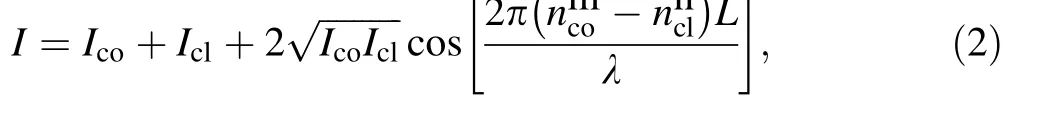
where Icoand Iclare the intensities of the core layer and cladding layer in the process of optical transmission, nmcoand nnclare the effective RI values of the core layer and higher-order cladding layer, L is the effective interference length of the sensor,λ is the wavelength of input light.The dips in the s-order interference spectrum(λs)depend on the following:

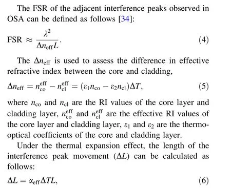
where αeffis the sum of the thermal expansion coefficients of the fiber and PDMS.
When the outside temperature changes,the RI of PDMS changes.Under the action of the PDMS,the RI of the fiber cladding will be indirectly affected, resulting in a shift in the resonance wavelength of the MZI. The wavelength offset of the interference dips(Δλ)is calculated as follows:

To further understand the light transmission principle of the SDNS sensor coated with the PDMS film,the light field was simulated using the BeamPROP module in RSoft software. It uses advanced finite difference beam propagation methods to simulate analytical optics. Its main program is a complete CAD design system for designing optical waveguide components and optical paths. The simulation program can perform a simulation analysis in the main program or independently, and display the characteristics of the domain and various numerical properties in a graphical way.The simulation parameters of the SMF,DCF, and NCF were set as follows: the core/cladding diameters of the SMF and DCF were 8.2/125 μm and 5/110 μm, respectively, and the cladding diameter of the NCF was 125 μm.The core/cladding RI values of the SMF and DCF were 1.465/1.445 and 1.4641/1.4584, respectively, and the cladding RI value of the NCF was 1.444.Figure 3a displays the optical field distribution of the SDNS sensor coated with the PDMS film at 22 °C, where the RI of PDMS is 1.4204. It can be seen that when the incident light was transmitted from the SMF to DCF,most of the light was transmitted in the core, with a small part transmitted in the cladding as a result of the core-diameter mismatch. When the light transmission continued to forward to the NCF, because of the core-diameter mismatch,multiple independent high-order modes were effectively excited and transmitted in the NCF, resulting in multimode interference. Finally, most of the cladding energy in the NCF was re-coupled back to the core of the SMF,while a small portion of the energy continued to travel through the cladding of the SMF. Figure 3b–e displays light field distribution diagrams of the cross sections of the lead-in SMF, DCF, NCF, and lead-out SMF, respectively. As shown in Fig. 3b, when light propagated in the lead-in SMF,the light energy was mainly concentrated in the fiber core. It is shown in Fig. 3c–e that part of the light energy leaked into the cladding layer because of the core-diameter mismatch.Finally,most of the light was transmitted in the core layer of the lead-out SMF, with a small part continuing to be transmitted in the cladding layer.

Fig. 3 (Color online) Beam propagation in free space at 1550 nm wavelength. a Light field distribution diagram of SDNS coated with PDMS at 22 °C.b Light field distribution map at the SMF-DCF cross section. c Light field distribution map at the DCF-NCF cross section. d Light field distribution map at the NCF-SMF crosssection. e The cross-sectional light field distribution of the lead-out SMF
2.3 Irradiation mechanism analysis of PDMS
As a polymer material, the physical morphology of PDMS is changed by irradiation [35]. The morphologic changes in the three samples before and after irradiation were observed using scanning electron microscopy(SEM).Figure 4a–c shows SEM images of the three samples before irradiation, while Fig. 4d–f shows SEM images of the three samples after irradiation. It was found that the surface of the PDMS coated on the optical fiber was relatively smooth before irradiation,while the crosslinking effect of irradiation made it rough. The morphology of the PDMS coated on the surface of the optical fiber changed after irradiation.
In general, polymers undergo a series of physical and chemical changes when exposed to radiation. The most important changes are polymer chain crosslinking and degradation [36], but because of the special molecular structure of PDMS, irradiation crosslinking is more significant under60Co-γ irradiation. Therefore, the crosslinking effect caused by irradiation was considered in the experiment. The irradiation crosslinking was mainly manifested as various free radicals generated in the PDMS after irradiation. Because of the high activity of these free radicals, the linear structure of the straight-chain could be transformed into a three-dimensional network structure through covalent bonds. Thus, the polymer could be crosslinked. After radiation crosslinking, the mechanical properties, heat resistance, chemical resistance, aging resistance, and other properties of polymer materials will be improved. Therefore, as the physical form and related chemical properties of the PDMS changed, its RI also changed as a result of the radiation crosslinking. This affected the interaction between the PDMS and optical fiber, and improved its thermal stability [37].

3 Experimental setups
3.1 Irradiation experiment
To study the effect of irradiation on the temperature characteristics of the SDNS sensor coated with the PDMS film,we chose an industrial60Co-γ source as the irradiation source (Henan Academy of Sciences Isotope Co., Ltd.),with a dose rate of 47 Gy/min.The total dose ranged from 30 to 60 kGy.
The fiber sample was placed in the irradiation chamber,the lead-in shield cable was connected to the BBS,and the lead-out shield cable was connected to the optical spectrum analyzer. In addition, the dose in the irradiation chamber was monitored through the irradiation center control room,and the radiation source was turned off after reaching the set radiation dose. After waiting for 30 s, the fiber sample was removed. A schematic diagram of the irradiation system is shown in Fig. 5.
3.2 Temperature measurement experiment
A device diagram of the temperature measurement experiment is shown in Fig. 6. The SDNS sensor coated with the PDMS film was fixed on a slide and placed in the thermostat. Then, the experimental temperature range was set at 30–100 °C, and the spectral data were recorded in 10 °C steps. To ensure the accuracy of the data, when the internal temperature of the thermostat rose to the preset temperature, it was kept at this temperature for 5 min, and then the data were recorded.
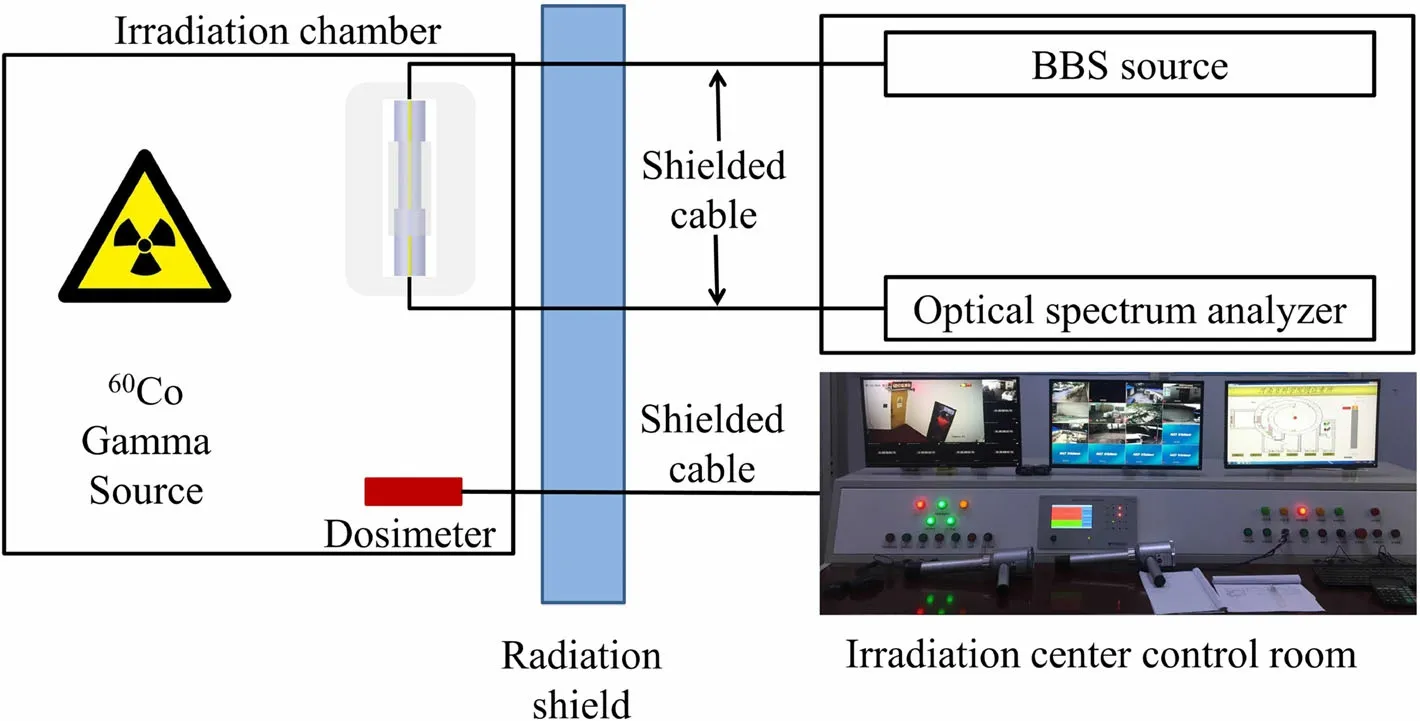
Fig. 5 (Color online)Schematic diagram of the irradiation system

Fig. 6 Diagram of the experimental device for temperature measurement
To study the influence of irradiation on the temperature performance of the SDNS sensor coated with the PDMS film, two temperature measurement experiments were conducted. One measured the temperature of the fiber samples before irradiation, and the other measured the temperature of the fiber samples after irradiation.Then,the spectral changes in the fiber samples before and after irradiation at different temperatures were compared.
4 Results and discussion
The temperature experiment was carried out after60Coγ irradiation with an irradiation dose of 50 kGy. Figure 7 shows the spectra of the SDNS sensor coated with the PMDS film before and after irradiation in the temperature range of 30–100 °C. It can be seen that at 30 °C, the spectrum before irradiation had four interference peaks in the wavelength range of 1515–1580 nm, and three interference peaks (dip A, dip B, and dip C) with relatively large ER values were selected for the experiment. The transmission values of dip A, dip B, and dip C could reach - 20.15 dB, - 23.00 dB, and - 19.71 dB, respectively.Similarly,there were also four interference peaks in the wavelength range of 1520–1595 nm after irradiation,and three interference peaks with relatively large ER values(dip A, dip B, and dip C) were also selected. Meanwhile,the transmission values of dip A, dip B, and dip C could reach - 35.66 dB, - 22.56 dB, and - 23.70 dB, respectively.It was also seen that,with the increased temperature,the three interference peaks moved in the direction of increasing wavelength.After irradiation,the position of dip A was shifted from 1523.4 to 1528.0 nm, the position of dip B was shifted from 1544.4 to 1547.8 nm, and the position of dip C was shifted from 1558.2 to 1570.2 nm.This was because the MZI formed by the SDNS sensor coated with the PDMS film was affected by the ambient temperature and radiation crosslinking effects, which changed the effective RI of the sensor,resulting in redshifts for dip A, dip B, and dip C.

Fig. 7 (Color online) Comparison of transmission spectra of SDNS sensor coated with PDMS film before and after irradiation at different temperatures: a transmission spectra of SDNS sensor coated with PDMS film at different temperatures before irradiation and b transmission spectra of SDNS sensor coated with PDMS film at different temperatures after irradiation
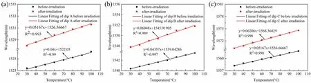
Fig. 8 Linear fitting results for dip A, dip B, and dip C wavelength shifts with temperature before and after the irradiation:a linear fitting results for wavelength and temperature of dip A before and after the irradiation, b linear fitting results for wavelength and temperature of dip B before and after the irradiation, and c linear fitting results for wavelength and temperature of dip C before and after the irradiation
To investigate the changes in the interference peak wavelength of the SDNS sensor coated with the PDMS film before and after the irradiation at different temperatures,the relationships between the temperature and wavelengths of dip A, dip B, and dip C were plotted, and the linear fitting results for the correlations are shown in Fig. 8.It can be observed that the temperature sensitivity values of dip A, dip B, and dip C before the irradiation were 40.00 pm/°C, 43.57 pm/°C, and 51.67 pm/°C, respectively, with linear fitting degree values of 0.990, 0.997, and 0.998,respectively. After the irradiation, the temperature sensitivity values of dip A,dip B,and dip C were 51.67 pm/°C,60.48 pm/°C, and 62.86 pm/°C, respectively, with linear fitting degree values of 0.993, 0.989, and 0.998, respectively.A comparison shows that the temperature sensitivity values of the SDNS sensor coated with the PDMS film after irradiation were higher than those before irradiation, with increases of 11.67 pm/°C, 16.91 pm/°C, and 11.19 pm/°C,respectively. The temperature sensitivity of dip C after irradiation was the highest, with a value that was approximately 1.22 times that before the irradiation.
To study the relationship between the transmission and temperature of the SDNS sensor coated with the PDMS film, the transmission changes in dip A, dip B, and dip C with the temperature change were plotted, and the fitting results are presented in Fig. 9. It can be seen that the transmissions of dip A and dip B had nonlinear fitting relationships with the temperature, while the transmission of dip C had a good linear relationship with the temperature.This indicated that the transmissions of dip A and dip B were unstable with a temperature change, with two or more temperature values obtained for the same transmission value. Therefore, dip C was chosen to reflect the one-to-one correspondence between the temperature and transmission. As shown in Fig. 9c, the transmission sensitivity of dip C before irradiation was 1.479 × 10⁻²dB/°C, and the linear fitting degree was 0.806. The transmission sensitivity of dip C after irradiation was 3.353 × 10⁻²dB/°C,and the linear fitting degree was 0.947. A comparison shows that the transmission sensitivity of dip C increased by 1.874 × 10⁻²dB/°C after irradiation, with a value that was approximately 2.267 times that before the irradiation, and it had a higher linear fitting degree.

Fig. 9 Fitting results for dip A, dip B, and dip C transmissions with temperature before and after irradiation: a polynomial fitting results for dip A transmission with temperature before and after irradiation,b polynomial fitting results for dip B transmission with temperature before and after irradiation, and c linear fitting results for dip C transmission with temperature before and after irradiation
To verify the repeatability of the SDNS sensor coated with the PDMS film, a repeated temperature measurement experiment was performed, with measurements made once a week for a total of three times. Meanwhile, the data for each temperature measurement experiment were recorded.The temperature range remained constant at 30–100 °C,and the temperature measurement procedure remained unchanged. The results of these repeated experiments are shown in Fig. 10.According to the linear fitting results for the temperature and wavelength of the repeated experiment,it can be seen that the error for the three temperature measurement results was relatively small, which indicated that in the temperature range of 30–100 °C, the SDNS sensor coated with the PDMS film had good temperature stability after irradiation,and could be reused in a radiation environment.
To further explore the influence of the irradiation dose on the temperature sensitivity of the SDNS sensor coated with the PDMS film, we compared the temperature sensitivity changes for dip A, dip B, and dip C under different irradiation doses.The cumulative doses were set to 0 kGy,30 kGy, and 60 kGy. At different irradiation doses, the changes in the fitting curves of the wavelengths of the three interference peaks with temperature are shown in Fig. 11.As shown in Fig. 11, the temperature sensitivity values of dip A,dip B,and dip C increased with the irradiation dose.Moreover, dip C had the highest temperature sensitivity,which indicated that within the dose range of 0–60 kGy,the irradiation crosslinking degree of the PDMS increased with the irradiation intensity, thus improving the temperature sensitivity of the sensor.
By comparing the temperature sensitivity, transmission sensitivity, and influence of the irradiation dose on the temperature sensitivity of the SDNS sensor coated with the PDMS film before and after irradiation, it could be concluded that among the three dips(dip A,dip B,and dip C)generated by the sensor,dip C had the highest temperature and transmission sensitivities. In addition, repeated temperature experiments showed that the sensor had good temperature repeatability. Therefore, the proposed SDNS sensor coated with the PDMS film had a good temperature performance and could be widely used for temperature measurement in a nuclear radiation environment.
5 Conclusion

Fig.10 (Color online)Results of repeated temperature measurement experiments for SDNS sensor coated with PDMS film:a linear fitting results for three temperature repetitions with dip A, b linear fitting results for three temperature repetitions with dip B,and c linear fitting results for three temperature repetitions with dip C

Fig. 11 (Color online) Linear fitting results for the wavelength and temperature of three interference peaks (dip A, dip B, and dip C)under different irradiation doses: a Linear fitting results for dip A wavelength and temperature at different irradiation doses, b linear fitting results for dip B wavelength and temperature at different irradiation doses,and c linear fitting results for dip C wavelength and temperature at different irradiation doses
An optical-fiber temperature sensor coated with a PDMS film was designed in this work. The performance of the sensor in a high-dose radiation environment was investigated by studying its temperature and transmission sensitivities,as well as the influence of the irradiation dose on the temperature sensitivity of the sensor. First, the optical simulation software RSoft was used to simulate the mode field distribution of the SDNS sensor coated with the PDMS film, and the light transmission process in the sensing structure was analyzed. Second, a comparison of the temperature sensitivity values of the sensor before and after irradiation proved that the sensor had a better temperature performance in a high-dose radiation environment.The experimental results showed that the temperature sensitivity of the SDNS sensor coated with the PDMS film was up to 62.86 pm/°C in a range of 30–100 °C after irradiation, which was approximately 1.22 times higher than that before irradiation. At the same time, the transmission sensitivity of dip C after irradiation was 3.353 × 10⁻²dB/°C, which was approximately 2.267 times that before irradiation, and a high linear fitting accuracy was also obtained. Third, repeated temperature measurement experiments proved that the SDNS sensor coated with the PDMS film had good stability.Finally,the irradiation crosslinking degree of the PDMS increased with the irradiation intensity, thus improving the temperature sensitivity of the sensor.Compared with other optical-fiber structures used for temperature measurement in a radiation environment,the SDNS sensor coated with the PDMS film has the advantages of a compact structure, simple manufacturing process, and high-temperature sensitivity, with the potential to be used for temperature measurement in a radiation environment.
AcknowledgementsWe thank the60Co-γ radiation operating team at the Isotope Research Institute Co., Ltd. of the Henan Academy of Sciences for their kind help and support during the experiments.
Author contributionsAll authors contributed to the study conception and design. Material preparation, data collection and analysis were performed by Fang Wang, Qiu-Feng Wu, Yu-Rong Jiang,Chan Jin, Xiao-Hui Wang, Ben-Shang Zhang, Chun-Wang Ma. The first draft of the manuscript was written by Fang Wang, and all authors commented on previous versions of the manuscript. All authors read and approved the final manuscript.
杂志排行

Nuclear Science and Techniques的其它文章
- Hard X-ray focusing resolution and efficiency test with a thickness correction multilayer Laue lens
- Monte Carlo study of the neutron ambient dose equivalent at the heavy ion medical machine in Wuwei
- Experimental investigation on the characteristics of molten lead–bismuth non-eutectic alloy fragmentation in water
- Configurational information entropy analysis of fragment mass cross distributions to determine the neutron skin thickness of projectile nuclei
- Differences in MBUs induced by high-energy and medium-energy heavy ions in 28 nm FPGAs
- Thin-film approximate point scattered function and its application to neutron radiography