Ablation characteristics of insulator under high-temperature gas dualpulse erosion
2022-10-17YangLiuXiaocongLiPengfeiZhuKunXi
Yang Liu ,Xiao-cong Li ,Peng-fei Zhu ,Kun Xi
a Northwestern Polytechnical University,710072,Xi'an,PR China
b Xi'an Modern Chemistry Research Institute,710065,PR China
c Department of Aerospace Propulsion Technology,Science and Technology on Combustion,Internal Flow and Thermal-Structure Laboratory,Shaanxi,PR China
Keywords:Dual-pulse solid rocket motor High temperature gas Ablation PSD Charred layer
ABSTRACT This study numerically simulated and investigated the flow field characteristics of a typical dual-pulse solid rocket motor with a soft pulse separation device through thermal insulation ablation under high-temperature dual-pulse erosion.The ablation rate of ethylene -propylene-diene monomer (EPDM)insulator was measured after the experiment.Experimental results were analyzed through scanning electron microscopy and microcomputed tomography.The ablation mechanism of the EPDM insulator under the operation conditions of a dual-pulse solid rocket motor was evaluated by analyzing the results.The results reveal that the internal flow field of the motor with a soft pulse separation device is uniform.The original charred layer existing on the EPDM insulator surface in the first pulse combustor is the decisive factor affecting the final ablation rate of the dual-pulse motor during the second pulse operation,and the ablation characteristic region is easily formed with the exfoliation of the charred layer.The ablation rate difference of the insulator increases with gas velocity.
1.Introduction
Dual-pulse solid rocket motors have attracted considerable attention from research institutes in various countries because of their high flight maneuverability,real-time energy distribution,and output during operation with a simple structure [1-4].The structure of a typical dual-pulse solid rocket motor is shown in Fig.1.The combustion chamber or pulse grain is divided into two parts using a pulse separation device(PSD).Each stage of the pulse grain has an independent ignition system,but the same nozzle is used.Ignition is controlled by timing during operation.The ablation of adiabatic materials in the combustion chamber is complex and presents different characteristics along the axial direction because of the unique working characteristics of dual-pulse solid rocket motors.In view of this characteristic,scholars have carried out research in different directions.
Bayern-chemie et al.[6] developed a soft pulse separation device for double pulse motors and tested it in ballistic flights.By means of these missiles the reliability,respectively the technical maturity of this PSD has been verified in two perfect test flights.Fan,Xing-gui et al.[7] characterized the rate-dependent deformation-failure behavior of pulse separation device (PSD) of ethylene propylene diene monomer (EPDM).An improved hyperviscoelastic constitutive model with an energy limiter (in which the constant energy limiter was replaced by a rate-dependent energy limiter) was proposed to predict the rate-dependent deformation-failure behavior of EPDM under quasi-static loading.C.G.Wang et al.[8]obtained the analytical method to compute the circumferential strain on a soft pulse separation device (PSD),deformation processes of the middle section of the soft PSD.Li Ying kun et al.[9]conducted numerically the second pulse ignition transient in a dual pulse solid rocket motor with elastomeric barrier pulse separation device.An in-house code has been developed to solve governing equations for unsteady compressible flow,heat conduction and structural dynamic.
Fig.1.[5] Longitudinal section of a dual-pulse solid rocket motor.
The internal flow field of dual-pulse solid rocket motors with hard PSD was comprehensively analyzed in detail in Ref.[10].Xu et al.[11]investigated the ablation of hard PSD.The separated eddy current was formed when the gas flowed through the separation device during the 2nd pulse ignition,and many dangerous reattachment points were locally produced,forming a surfaceenhanced heat transfer area that caused abnormal ablation of the insulation layer.
Ethylene-propylene-diene monomer (EPDM) rubber-based insulation materials are widely used in the insulation layer of solid rocket motors because of their good performance [2].The high-temperature gas generated during motor operation exceeds the allowable temperature of the alloy steel motor shell.EPDM insulation materials consumes their quality through ablation to protect the structural integrity of the motor shell,avoid burning of the contact part between the shell and gas,and reduce the structural strength caused by material overheating.The charred reaction of EPDM-based insulation materials occurs during ablation,thus forming a charred layer on the surface.The charred layer is an important barrier to resist high-temperature gas and particle erosion.Hence,this layer is the object of the direct action of the thermochemical ablation reaction,mechanical denudation effect,and particle erosion [12].Theoretical studies on the ablation mechanism of EPDM-based insulation materials around the world have shown that the compact structure of the charred layer plays an important role in delaying the ablation of insulation materials and improving the erosion resistance.Theoretical analysis shows that the influence of the dense structure of the charred layer on the ablation of insulation materials is mainly reflected in the following aspects.1)The charred layer reduces the diffusion rate of gas containing oxidizing components caused by propellant combustion to adiabatic materials through the pore channels,hindering the thermochemical ablation.2)The charred layer prevents the pyrolysis gas caused by the thermal decomposition of adiabatic materials at high temperature from spilling through the pore channels and increases the concentration of local pyrolysis gas,inhibiting the pyrolysis of adiabatic materials.3)The compact structure has higher strength and mechanical properties than that of the porous part of the charred layer,improving the resistance of the charred layer to mechanical erosion and particle erosion [13].
Studies on the ablation mechanism of adiabatic materials have gradually shifted from the macro level to the micro level,and many studies have focused on the pore structure and the physical and chemical processes of the charred layer.Curry's analysis of the Apollo spacecraft thermal protection system (external protection)indicated the occurrence of complex physical and chemical processes in the thermal protection material,where pyrolysis gas splits into small molecules,generates carbon and deposits on the framework,and reduces the porosity [14].Li et al.[15,16] investigated the ablation characteristics of EPDM insulation materials.A coupled ablation model of EPDM insulation materials considering thermal chemical ablation,particle erosion,mechanical denudation effect,and deposition reaction was presented on the basis of the relevant basic theories and calculation methods in porous media and using the pore structure characteristics and parameters of charred layers.Preliminary experimental verification showed that the calculated results are in good agreement with the experimental results.Li et al.[17,18] intensively evaluated the ablation mechanism of thermal insulation materials.The results showed that the“dense/loose” phenomenon appears in the pore structure of the charred layer,and the formation mechanism of the dense structure of the charred layer was theoretically analyzed.The deposition densification hypothesis was established.The pyrolysis gas of hydrocarbon production by the thermal decomposition of thermal insulation materials reacted with the substrate of charred layers at appropriate temperature ranges,and the reaction products promoted the growth of local carbon skeleton to form a dense structure.
With the development of large-diameter and filament-wound shell motors,soft pulse spacing devices have been widely used in advanced dual-pulse solid rocket motors because they can simultaneously serve as a flame retardant and heat insulation at the same time.Systematic studies on the flow characteristics and the thermal insulation ablation of dual-pulse solid rocket motors with soft pulse separation devices have not been conducted.The flow field characteristics of a typical dual-pulse solid rocket motor with soft PSD were simulated and investigated through the ablation of insulation materials under two times of high-temperature gas erosion.The EPDM-based thermal insulation materials was used as the research object to evaluate the ablation characteristics of thermal insulation material under two times of high pressure and high-temperature gas scouring [19,20].Firstly four different flow channel configurations of the motor combustion chamber at different times were selected,and a 3D two-phase numerical simulation was conducted on the basis of the X-ray test results.Then The ablation rate of the thermal insulation material and the microstructure and morphology of the charred layer after the experiment were obtained,and the ablation of the composite material on the dualpulse solid rocket motor was analyzed.
2.Analysis of flow characteristics of 1st pulse combustor
2.1.Analysis of internal flow field
Fig.2.Schematic of a dual-pulse solid rocket motor with a soft pulse interval device.
The flow characteristics in the combustion chamber of dualpulse solid rocket motors should be understood to investigate the ablation mechanism of EPDM in such motors.A typical dual-pulse solid rocket motor (Fig.2) with soft PSD was taken as the research object in this study.Previous research showed that the pulse interval device has a significant impact on the flow field,directly affecting the gas flow pattern and heat exchange on the wall of the combustion chamber.According to Martin H T et al.‘s[21] research method,an X-ray screen real-time diagnosis system was used to conduct the real-time noncontact measurement of the opening and deformation of pulse interval devices during the motor operation.Such a measurement aims to simulate the real internal flow field characteristics of the motor accurately.The geometry of the soft PSD after opening and the shape under the action of gas were obtained.The real-time diagnosis results showed that the dual-pulse solid rocket motor of the soft PSD had a bending deformation during the 2nd pulse operation under the action of gas,and its shape and geometric size were different from the operation time.
2.2.Numerical solution method
Four different flow channel configurations of the motor combustion chamber at different times (2 s,5 s,7 s,9 s) were selected,and a 3D two-phase numerical simulation was conducted on the basis of the X-ray test results.The Reynolds-averaged Navier--Stokes equation was used in the numerical simulation,and Lagrangian and Euler methods were used to describe the discrete and continuous phases,respectively.The RNGε turbulence model was employed to obtain a closure equation,and a random orbit model was used to consider the influence of turbulence diffusion on particle motion.Fig.3 shows the grid division diagram of the calculation area of the internal flow field of a typical dualpulse solid rocket motor at a certain time.All the flow channels were divided using the structural grid,thereby resulting in a total of 852000.The combustion,fragmentation,and coalescence of particles were ignored in the calculation.The particle diameter was given on the basis of R-R distribution,and the medium diameter was 10 μm.Three kinds of boundaries were used in the numerical simulation(as shown in Fig.3.The propellant burning surface was the mass flow inlet,and the flow flux,total gas temperature,and turbulence parameters were given.The nozzle outlet was the static pressure outlet,and the outlet pressure,static temperature,and turbulence parameters were given.The combustion chamber,pulse interval device,and nozzle wall were all nonslip adiabatic boundaries.A rebound model was used between the condensed particles and the wall.The normal and tangent recovery coefficients were 0.8.Table 1 shows the pulse operation parameters of the 2nd motor and the combustion products of the propellant.

Table 1 Operation and combustion product parameters in the 2nd chamber.

Fig.3.Computational zone and boundary.
2.3.Analysis of calculation results
Fig.4 shows the flow streamline and particle concentration cloud diagram in the motor.The gas forms a local return area behind the isolation device and the wall area in the middle of the combustion chamber under the obstruction of the isolation device.The back end of the combustor forms a circumfluence vortex.Most of the particles flow from the combustion surface to the main stream and out of the nozzle.The central and wall regions of the combustion chamber form an uneven distribution of particle concentration.Simultaneously,a certain concentration of particles gathers near the wall of the combustion chamber middle region and that of the rear head because of gas backflow effect.The particle concentration near the wall in the middle area of the aggregation site is relatively uniform,and that near the bottom of the submerged nozzle end is slightly higher than that in the middle area (see Fig.5).
Compared with the flow characteristics of the dual-pulse solid rocket motor with hard PSD[3,4],the bending of soft PSD caused by the action of gas results in an increase in the interstage channel area,which results in low concentrations of condensed phase particles near the combustion chamber wall.Simultaneously,the gas flow from the 2nd pulse combustion chamber to the 1st pulse combustion chamber is stable,the eddy current formation is small,and the position is forward,which is consistent with the research results of Chen [9].
A 3D two-phase numerical simulation was conducted on four different motor flow channels to obtain comprehensive flow characteristics of the combustion chamber.The results showed that the flow field parameters are similar to the particle concentration distribution.The axial direction of the combustion chamber can divided into the front,middle,and back section based on the flow characteristics of the area near the wall.The vortex size in the back part of the isolation device was small,mainly in the form of the corner and shedding vortices at the downstream root and the head of the isolation device,respectively.Large-scale circumfluence vortices near the wall in the middle section of the combustor were observed.The average gas velocities were 0-5,12-18,and 3-8 m/s in the front,middle,and back sections and the combustor.Despite the presence of some differences in the particle concentration of each characteristic area in the combustion chamber,its absolute value was small(<6 kg/m)and its speed was low(<5 m/s)based on the comparative analysis of the calculation results at different times.These value were less than the weak scour mode in theparticle scour mode.Therefore,particle erosion was not the main reason for the ablation difference of the thermal insulation in each region of the combustion chamber.

Fig.4.Two-phase flow characteristics and stream line in the 1st pulse chamber at t3.
Schilling et al.[29]believed that the increase in ablation of the insulation layer of dual-pulse solid rocket motors is caused by the enhanced heat transfer due to uneven flow.The numerical simulation of the wall thermal environment at four different times was conducted to investigate the effect of flow on heat transfer.Fig.6 shows the Nusselt number distribution along the axial wall of the combustor at different working times.The heat transfer characteristic parameters had the same distribution rule at different times.The heat transfer from the pulse interval device to the back gradually increased and reached the maximum value at the middle of the combustion chamber and gradually decreased and increased at the end of the combustion chamber.This phenomenon was consistent with the flow vortex structure distribution of the motor flow field.
Fig.7 shows the ablation rate of 1st pulse combustor in different quadrants after the full-scale motor ground test.The ablation rate of the insulation layer in the 1st pulse combustor slightly varies in different quadrants along the circular direction,but gradually increases along the axial direction.The average ablation rates of the front,middle,and back sections of the combustor are 0.102,0.150 and 0.310 mm/s,respectively,which is three times of the front and two times of the middle of the combustor.The comparison results of Nusselt number and adiabatic ablation rate Figs.7 and 8 combined with the previous research result revealed that gas velocity and enhanced heat transfer of the flow vortex to the wall are the main factors that increase the ablation rate in the middle section of combustion chamber [2-4].The ablation rate of the thermal insulation layer in the back section of the combustion chamber is the highest,but the gas velocity and Nusselt number on the wall are lower than that in the middle section of the combustion chamber.Fragments of the charred layer were also ejected from the combustion chamber during the 2nd pulse operation.Therefore,the gas shearing in the back-end return zone of the combustor may cause the removal of the charred layer,aggravating the ablation ofthe heat insulation layer in the submerged cavity to form the ablation characteristic area.
Fig.5.The velocity contours in the 1st pulse chamber at t3.
Fig.6.Nusselt number distribution along the flow path at different times.

Fig.7.Ablation rate in the 1st pulse chamber.
3.Ablation law under different influence factors
3.1.Formula of thermal insulation material
The EPDM rubber was provided by Mitsui Group Co.,Ltd.The third monomer was ethylidene norbornene with 45% ethylene content.The phenolic resin was provided by Shengquan Group Co.,Ltd.,China.The aramid fiber was provided by DuPont Co.,Ltd,China.Silica was supplied by Cabot Ltd.,China.Zinc borate was provided by Taixing Group Co.,Ltd.,China.The formulation of the EPDM composite in this experiment is listed in Table 2.
The formula proportion in Table 1 shows that the compounds of EPDM,phenolic resin,aramid fiber,silica,and other fillers were prepared using an XK-160 mixed roller mill.Zinc borate,sulfur,and vulcanizing accelerator were added and ground several times for 24 h.EPDM was cut,molded,and vulcanized with tools.The elastomer compound was molded into a 10 mm thick slab.The vulcanized product was prepared through curing at 433 K for 50 min at a pressure of approximately 15 MPa.

Table 2 EPDM composite formula (phr)a.
3.2.Simulated dual-pulse ablation experiment
A ground ablation experimental device was designed for the working characteristics of the dual-pulse solid rocket motor.This device aim to analyze the ablation characteristics of the insulationlayer in the 1st pulse combustion chamber of the dual-pulse solid rocket motor and to verify the above analysis.The main characteristic of the dual-pulse solid rocket motor was two times higher than that of the pulse operation,and the insulation layer in 1st pulse combustion chamber was eroded and ablated by two times of the high temperature and high pressure gas.The main factors affecting the ablation of the thermal insulation layer were as follow:the intensified heat exchange caused by gas velocity and the mechanical erosion effect of gas based on the flow characteristics analysis in the motor chamber of the motor and the ablation experiment results of the full-scale motor.Therefore,the gas velocity and charred layer removal were considered the main variables in the design of the experimental scheme.
Existing studies have shown that the ablation rate of the insulation layer will substantially change when the gas speed is higher than 20 m/s under the gas environment with low particle concentration.Therefore,two ablation test sections,namely low-speed and high-speed test sections,were designed for the test device based on the speed range combined with the flow characteristics of the real motor.Fig.8 shows the proposed gas ablation simulation experimental device,which mainly comprises the following:combustion chamber,propellant,low-speed test piece,convergence section,high-speed test piece,high-speed test section,and nozzle.Fig.9 shows the picture of an ablation motor.The same working pressure,propellant,and thermal insulation material of full-scale motor were used in the experiment to reflect the ablation and characteristics of the thermal insulation material under the real working conditions of the motor.The low-speed test section was installed at the end of the combustion chamber,and the gas velocity on the wall was close to 0 m/s for the thermochemical ablation simulation of the thermal insulation material test piece.The cross-sectional area of the flow passage in the high-speed test section was changed by altering the test clamps with different thicknesses to realize the change in gas velocity near the surface of the thermal insulation material test piece.Two kinds of high-speed specimen clamps were designed,and the corresponding gas velocities were 15 and 30 m/s.
A 3D two-phase numerical simulation was conducted on the designed experimental device.Fig.9 shows the particle concentration distribution in the flow field and the velocity distribution in the cross-section of the low-and high-speed test sections.The cross-section velocity of the low-and high-speed sections met the design requirements based on the calculation results.The range of high particle concentration was close to the center of the flow passage.Thus,the influence of particles on the ablation results of the insulation material can be ignored.

Fig.8.Sketch of ablation experimental installation under gas erosion.1.combustion chamber;2.propellant;3.low-speed test piece;4.convergence section;5.high-speed test piece;6.high-speed test section;7.nozzle;8.base of test piece clamp;9.specimen clip;10.thermal insulation test piece;11.thermal insulation test piece;and 12.specimen clip.
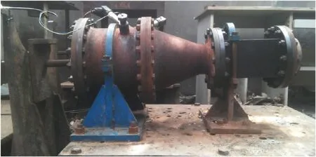
Fig.9.Photo of ablative motor.
Two times of erosion and ablation of the insulation specimen under high temperature and high-pressure gas of a dual-pulse solid rocket motor were simulated using the ground experiment device.The investigated thermal insulation material test piece was placed in the ablation experiment section to simulate the first pulse working environment.The test piece was removed and kept intact after experiment,and its thickness and quality were measured.The experimental piece was placed in the second ablation experiment section after a certain time interval to simulate the second pulse working environment.The design of the two experiments were based on the ignition experiment of the dual-pulse solid rocket motor and the calculation results of the internal flow field.The different states of the first ignition of different dual-pulse solid rocket motors can be simulated by adjusting the structural parameters of the motor and the selection of the propellant.The regulation of the working conditions of the second stage motor is the same.Therefore,the experiment is divided into two parts:the first and second ablation of thermal insulation materials.In the first experiment,the samples of thermal insulation materials were prepared for the second ablation experiment.The charred layer on the EPDM surface was brittle and easily damaged during the solid rocket motors operation.Obtaining an intact insulation material after the first ablation is important for the second ablation experiment.The first ablation sampling experimental device of thermal insulation materials were designed in this section based on the thermochemical ablation effect.The samples of thermal insulation materials were prepared for their subsequent second ablation and the samples of EPDM thermal insulation materials were analyzed through electron microscopy and energy spectroscopy.Tables 3 and 4 provide the lists of experimental schemes,in which the charred layer formation experiment is the first ablation experiment using the ablation time and gas erosion speed as variables.Such schemes mainly aim to simulate the generation of charred layer test pieces in the first pulse of dual-pulse solid rocket motors during operation.The charred layer samples produced in the first experiment were used in the second ablation experiment,and the working time of ablation,completion or peeling (artificial peeling) of the charred layer,and the velocity of gas erosion were taken as variables.The numbers in the table denote the number of charred layer test pieces,and superscripts a,b …,h represent the corresponding specimen under different working conditions in the charred layer formation experiment.Two specimens were used in the erosion experiment of the charred layer (second ablation experiment) to avoid the randomness of the experimental process.
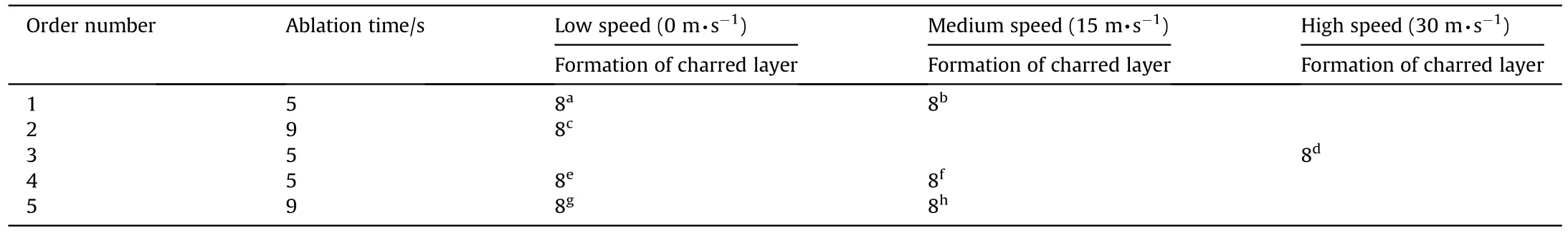
Table 3 Charred layer formation experiment (first ablation experiment).
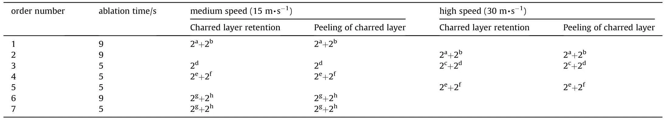
Table 4 Erosion test of charred layer (second ablation test).
3.3.Test and analysis device
The microstructure and the element composition of the carbon layer were comprehensively analyzed through scanning electronmicroscopy (SEM) (model:JEOL JSM-6390 A)and the energydispersive X-ray spectroscopy (EDS),respectively.Microcomputed tomography(CT)(model:YXLON Y-Cheetah,resolution:1.5 μm)was used to observe the microstructure of the carbon layer.

Fig.10.Time-pressure curve of simulated dual-pulse ablation experiment.
4.Analysis of experimental results
4.1.Ablation test results
Fig.10 shows the pressure-time curve after the simulated dualpulse ablation experiment,where Fig.10 (a) and 10 (b) show the results of simulated 1st and 2nd pulse ablation experiments,respectively.The average working pressure of the two ablation experiments is 8.5 MPa,and the pressure is relatively stable during the experiment.The working time is approximately 4.5 s.The starting working time is defined as the time when the pressure increases to 5% of the average working pressure,the ending working time is the time when the pressure drops to 850 kPa,and the working time is the duration between the two.
4.2.Analysis of ablation rate results
Table 5 shows the statistical results of the ablation rate of EPDM insulation materials under typical working conditions after the simulated dual-pulse ablation experiment.The ablation rate refers to the ablation rate of the heat insulation material.The calculation formula of the ablation rate of heat insulation material with the retained charred layer is expressed as follows: (thickness of the heat insulation layer before the first ablation experiment -thickness of the base layer of the heat insulation material after the second ablation experiment)/total ablation time of the two experiments.The ablation rate of the thermal insulation material with a peeled charred layer is expressed as follows:(-thickness of the thermal insulation base layer with a peeled charred layer after the first inspection-thickness of the thermal insulation base layer after the second ablation experiment)/ablation time of the second experiment.
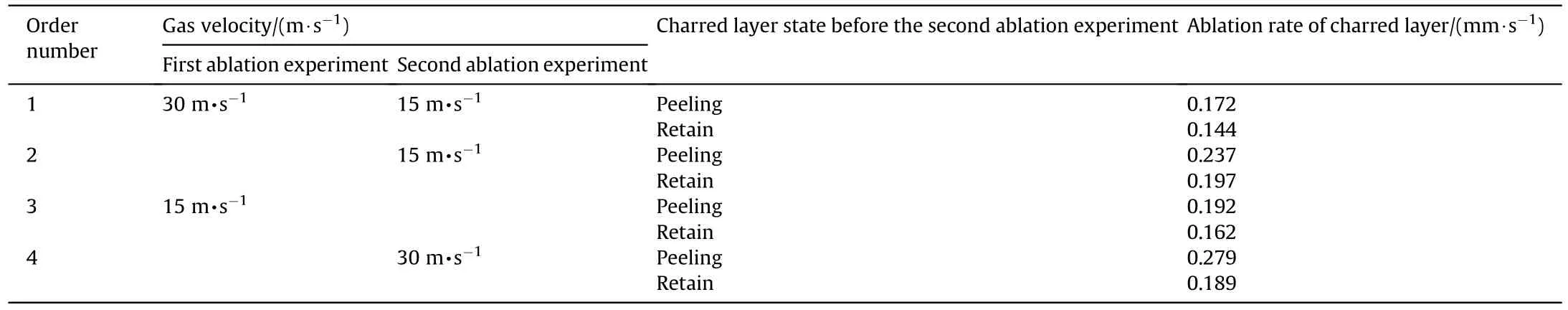
Table 5 Typical experimental ablation rate data.
The comparison of cases 1 and 2 shows that the working time of the second ablation experiment has a considerable influence on theablation rate,and the ablation rate under the working time of 7.7 s is approximately 1.37 times higher than that under the working time of 4.7 s.The comparison of cases 2 and 3 shows that the gas velocity of the first ablation experiment has a certain influence on the ablation rate of thermal insulation materials,which is approximately 1.2 times higher at high speed than that at low speed.The comparison of cases 3 and 4 shows the complex influence of gas velocity in the second ablation experiment on the ablation rate of thermal insulation materials.The ablation rate at high speed is approximately 1.1 times higher than that at low speed for the ablation rate of specimens with retained charred layer,whereas that high speed is approximately 1.4 times higher than that at low speed for specimens with a peeled charred layer.The ablation rate of the specimens with peeled carbon layer at high speed is 1.7-2 times higher than that of the specimens with preserved carbon layer at low speed.The average ablation rate after the first ablation experiment is 0.235 mm/s at 15 m/s measured gas velocity.This rate is close to that of 0.243 mm/s in the second ablation experiment of the peeled group.
4.3.Analysis of charred layer microstructure
Figs.11-14 respectively show the SEM photos of the charred layer surfaces after the first ablation at low speed,the second ablation at low speed,the first ablation at high speed and the second ablation at high speed.As shown in Fig.11,the surface of the charred layer is relatively dense under low-speed gas after the 1st pulse test with a certain amount of distributed holes,and a large number of flocculent deposits are attached to the surface.The analysis of literature [22,23]reveals that the spherical particles on the charred layer surface are alumina particles produced through composite propulsion combustion.The surface of the charred layer in Fig.12 is denser than that of the 1st pulse charred layer,and deposits are not observed on the surface.The results show the low gas velocity in the combustion chamber in the 1st pulse operation and the easy adherence of AlOparticles in the gas near the wall to the charred layer surface.The fuel gas is helpful in the removal of substances attached to the charred layer before blowing during the 2nd pulse operation.Fig.13 shows that,the charred layer surface under high-speed gas conditions in the 1st pulse ablation experiment demonstrates a pore structure with an average pore diameter of approximately 20 μm compared with that under low-speed gas condition.According to the ablation mechanism described in Ref.[17]combined with that of the thermal insulation material,the interconnected pore structure is conducive to the pyrolysis gas overflow of the thermal insulation material and the charred layer internal diffusion of the oxidation component phase in the gas to intensify ablation.The pore diameter of the charred layer increases under high-speed gas after the 2nd pulse experiment,and the average pore diameter is approximately 50 μm.The enhancement effect of chemical vapor deposition on the charred layer under this condition is less than the thermochemical ablation effect of oxidizing components in gas [13-17].

Fig.11.SEM photo of the charred layer surface after simulated 1st pulse ablation at low speed.
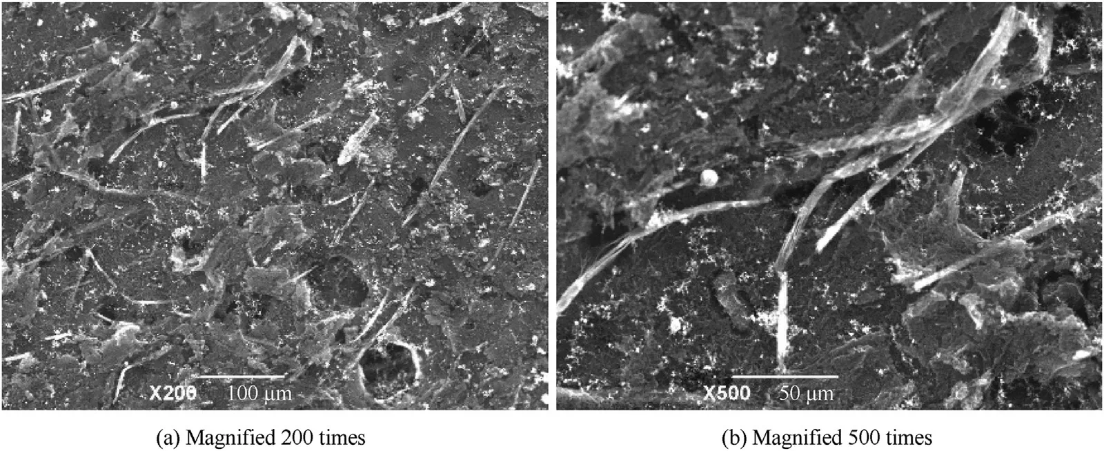
Fig.12.SEM photos of charred layer surface after simulated 2nd pulse ablation at low speed.
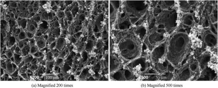
Fig.13.SEM photos of charred layer surface after simulated 1st pulse ablation at high speed.

Fig.14.SEM photos of the charred layer surface after simulated 2nd pulse ablation at high speed.

Fig.15.SEM of charred layer section after.simulated 1st pulse ablation.

Fig.16.SEM of charred layer section after 2nd pulse.ablation of retention group simulation.

Fig.17.Relative density of charred layer after simulated 1st pulse ablation.
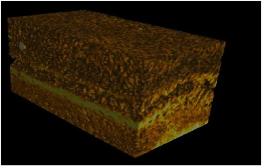
Fig.18.Relative density of charred layer after 2nd pulse ablation of retention group simulation.
Figs.15 and 16 show the SEM photos of charred layer sections after simulated 1st and 2nd pulse ablation experiments,respectively.Meanwhile Figs.17 and 18 show the relative density distribution of the reconstructed charred layer through micro CT.Fig.15 reveals that the charred layer formed by EPDM composite during the simulated 1st pulse ablation experiment has a loose structure and a large pore diameter.After the simulated 2nd pulse ablation experiment,the charred layers of the reserved samples all show a dual-layer structure.A gap is also found between the two layers of the charred layer.The analysis shows that the upper and lower layers are the charred layer formed by the EPDM insulation material and the newly formed charred layer after the simulated 1st pulse ablation experiment and during the simulated 2nd pulse ablation experiment,respectively.The newly formed charred layer demonstrates a“compact/loose”mechanism.The pore structure in the upper part of the charred layer is compact with a small pore diameter,the pore structure in the lower part is loose with large pore diameter,and the overall pore structure is more compact than that formed in the simulated 1st pulse ablation experiment.The analysis of relevant literature [17,18,24-28]indicates that the existence of the upper charred layer in the simulated 2nd pulse ablation experiment hinders the hydrocarbon gas overflow from the pyrolysis of the original layer of the thermal insulation material during the 2nd pulse operation.This phenomenon results in several pyrolysis gas chemical vapor deposition reactions in the new charred layer.The reaction products also promote the growth of the charred layer skeleton,leading to dense pore structures.The pyrolysis gas concentration in the middle and upper parts of the lower charred layer as well as the reaction temperature are high.
Table 6 shows the EDS results in different parts of the charred layer in Fig.16.The relative contents of elements in the prepared charred layer slightly change in the ablation direction,whereas those of Si and O elements in the bottom area and newly formed charred layer are significantly high.Combined with the fluid-like substances between the two charred layers,the SiOliquid film increases the relative content of elements in this area.Simultaneously,the SiOliquid film obstructs the overflow of pyrolysis gas.Such obstruction leads to the accumulation of pyrolysis gas in the upper part of the charred layer and the promotion of the deposition reaction of pyrolysis gas in this area.

Table 6 Element distribution of the charred layer test piece.
The analysis shows that the dual-layer charred mechanism formed in the 2nd pulse ablation improves the ablation resistance of thermal insulation materials,which is mainly reflected in the following aspect.First,the existence of the upper charred layer avoids the heat conduction of high-temperature gas to the insulation material matrix through convection heat transfer.This condition hinders the production rate of pyrolysis gas by the pyrolysis layer of the insulation material overflowing to the outside and improves the local pyrolysis gas concentration,delaying the pyrolysis of the insulation material.Second,this condition hinders the diffusion rate of the oxidizable components in the fuel gas from the propellant through the pore structure of the charred layer to the inner part of the thermal insulation material,thereby delaying the thermochemical ablation.Finally,the existence of the upper charred layer can resist mechanical damage during gas and particle erosion.
The damage and removal of the charred layer formation in 1st pulse operation during the 2nd pulse operation mainly cause the ablation rate different in the 1st pulse combustion chamber thermal insulation material under the working condition of the dualpulse solid rocket motor.The difference in ablation rate increases with the gas velocity.The ablation mechanism of thermal insulation materials in DPE is the same as that in traditional SRM,but the ablation is complicated.
5.Conclusion
In this paper,the PSD structure of double pulse solid rocket motor is studied,which is divided into two parts: numerical simulation and experimental research.Firstly four different flow channel configurations of the motor combustion chamber at different times were selected,and a 3D two-phase numerical simulation was conducted on the basis of the X-ray test results.Then The ablation rate of the thermal insulation material and the microstructure and morphology of the charred layer after the experiment were obtained,and the ablation of the composite material on the dual-pulse solid rocket motor was analyzed.The conclusions and future research plan are as follows:
(1) The thermal environment of the thermal insulation material in the combustion chamber during the operation of dualpulse solid rocket motors is similar to that of traditional solid rocket motors through numerical simulation.This environment has the characteristics of high temperature,high pressure,and low gas velocity.
(2) In two complete pulse working cycles of dual-pulse solid rocket motors,the final ablation rate of the insulation material is directly related to the charred layer on the insulation when the material is retained in the initial stage of the 2nd pulse operation.The ablation rate during the 2nd pulse working period is large when the charred layer is not retained,which is 1.7-2 times higher than that of the ablation rate of the retained charred layer.
(3) Forming a dual charred layer structure in the working process of the 2nd pulse solid rocket motor is easy.The analysis shows that the upper charred layer can resist the convective heat transfer between the gas and the newly formed charred layer,thereby weakening the heat transfer.Simultaneously,the upper charred layer prevents the diffusion of oxidizing gas components into the new charred layer and delays the thermochemical ablation.The silica liquid film hinders the gas overflow from the pyrolysis layer of the thermal insulation material and promotes the chemical vapor deposition of pyrolysis gas to form a dense charred layer structure.
(4) We intend to further study the chemical reaction kinetics in PSD under two pulses.
The authors declare that they have no known competing financial interests or personal relationships that could have appeared to influence the work reported in this paper.
This work was financially supported by the National Natural Science Foundation of China,under grant numbers 51876177,51276150,and 51576165.
杂志排行

Defence Technology的其它文章
- Establishment,simulation and verification of firepower safety control model
- Burning characteristics of high density foamed GAP/CL-20 propellants
- Cell-type continuous electromagnetic radiation system generating millimeter waves for active denial system applications
- Sandwich structure for enhancing the interface reaction of hexanitrohexaazaisowurtzitane and nanoporous carbon scaffolds film to improve the thermal decomposition performance
- Influence of shaped charge structure parameters on the formation of linear explosively formed projectiles
- Novel aluminum-based fuel: Facile preparation to improve thermal reactions