基于石英MEMS技术的光纤法布里-珀罗高温压力传感器
2022-07-27李加顺贾平岗王军刘佳安国文熊继军
李加顺,贾平岗,王军,刘佳,安国文,熊继军
(中北大学仪器与电子学院动态测试技术省部共建国家重点实验室,太原 030051)
0 Introduction
Dynamic pressure measurements under high-temperature and other harsh environments,such as the pressure monitoring in aerospace engines[1-3],on-line health monitoring and control of molten salt reactors and gas-cooled reactors in nuclear applications[4],in-cylinder pressure monitoring in the automotive internal combustion engines[5],have a wide range of application requirements.At present,the sensors used for dynamic pressure measurement include electronic pressure sensors,such as piezoelectric[6],piezoresistive[7]and capacitive pressure sensors[5].However,the pressure sensors are often exposed to harsh environments such as high temperature and corrosion in the above application areas.And these sensors are highly dependent on temperature or close proximity electronics,limiting their high-temperature capabilities[8].In order to effectively protect electronic pressure sensors used in harsh environments,the engineering solutions,such as impulse lines,have been used to isolate sensors sensitive to heat and corrosion[4].But the impulse lines can also dampen the pressure signals,which will make it difficult to achieve in situ dynamic pressure monitoring,and increase the likelihood of blockages or bubbles impacting pressure measurements[9].
Compared with electronic pressure sensors,fiber-optic pressure sensors have attracted widespread attention due to their high-temperature resistance,high sensitivity,anti-electromagnetic interference,corrosion resistance,simple structure,and small size[10-13].At present,most of the reported fiber-optic pressure sensors are used for static pressure measurement and various types of fiber-optic Fabry-Perot(FP)pressure sensors have been fabricated using the MEMS[14-20],chemical corrosion[21],arc-discharge[12-22],laser processing techniques[11,23,24].Among them,the pressure sensors fabricated by chemical corrosion,arc discharge and laser processing technology are usually produced in a single piece,which results in poor consistency between sensors.By contrast,the MEMS technique can be applied in mass production and the materials used to fabricate fiberoptic pressure sensors by MEMS technology mainly include silicon[14-17],Pyrex glass[14-16],sapphire[18,19],etc.Due to the limitation of temperature resistance of the material itself,the pressure sensors made by silicon-glass bonding will have a lower operating temperature.And if different materials are used to fabricate the fiber-optic sensor or use adhesive to realize the connection between the sensor head and optical fiber,the mismatch of the Coefficients of Thermal Expansion(CTE)between different materials will easily reduce the sensor stability and result in large temperature cross-sensitivity in the high temperature environment.For instance,JIA Pinggang et al.[14]presented a high-temperature fiber-optic FP pressure sensor fabricated by anodically bonding the Pyrex glass wafer and silicon wafer and realized static pressure measurement at 350 °C.LI Wangwang et al.[18]demonstrated a fiber-optic high temperature pressure sensor based on sapphire direct bonding and experimental results demonstrate the sensing capabilities for static pressures,but the temperature coefficient of sapphire sensor is relatively large,approximately 1.25 nm/°C.
In this paper,we propose a MEMS-based all-silica fiber-optic Fabry-Perot dynamic pressure sensor used the silica wafer with ultralow CTE and softening point as high as about 1 750 °C.The sensor heads are batchfabricated with silica wafers using MEMS technique and three-layer silica direct bonding technology,which ensures consistency in the sensor heads and cost effectiveness and have the desired pressure measurement range and sensitivity by flexibly designing the related parameters.The all-silica adhesive-free integration between the sensor head and the optical fiber is achieved using CO2laser fusion.The sensor exhibits an ultralow thermal drift and good thermal stability owing to the low CTE of silica and the all-silica adhesive-free design,which can effectively avoid the sensor damage induced by the CTE mismatch of different materials at high temperatures and increase the lifetime of the sensor in high temperature environments.Moreover,the proposed sensor was subjected to a static pressure measurement at a high temperature of 800 °C and a 2 kHz dynamic pressure test at a normal temperature to verify the performance of the sensor.
1 Sensor working principle
The proposed all-silica pressure sensor comprises a sensor head,Hollow Silica Tube(HST),and goldcoated Multimode Fiber(MMF),as shown in Fig.1(a).Among them,the sensor heads formed by a silica diaphragm,a silica cavity,and a silica pedestal are batch-fabricated with silica wafers using the MEMS technique and the three-layer silica direct bonding technology.The gold-coated MMF is inserted into the HST and aligned with the silica cavity and the silica sensing diaphragm of the all-silica pressure sensor.Thus,a lowfinesse FP cavity is formed between the diaphragm and the bottom surface of the silica cavity.The low-finesse FP interference spectrum responds to the changes in the cavity induced by the external pressure.The sensor head,HST,and gold-coated MMF are fused using the CO2laser.Therefore,the proposed pressure sensor has an all-silica adhesive-free structure.

Fig.1 All-silica fiber-optic FP pressure sensor
Fig.1(b)shows a working mechanism of the all-silica pressure sensor.The gold-coated MMF is a lead-in fiber in the proposed sensor.The inner surface(R1)of the silica diaphragm and the bottom surface(R2)of the silica cavity from a low-finesse FP cavity.The distance between the bottom surface and the polished inner surface of the silica diaphragm is delimited as FP cavity length(L).When incident light passes through the FP cavity,multi-beam interference occurs between the two interfaces of the FP cavity.Owing to the low reflectivity(approximately 0.04)of R1 and R2,the reflection spectrum can be estimated as a two-beam interferometer model.The FP cavity length is a function of the detected parameters and can thus be extracted.The reflection spectrum of the FP interferometer is considered as an intensity modulation signal originating from the optical phase difference between the two reflections,as shown in Fig.1(c).The intensity of the reflection spectrum can be expressed as[25]

whereIis the intensity of the interference spectrum,I1andI2are intensities of the two reflections(R1 and R2),nis the refractive index of the medium in the FP cavity,Lis the FP cavity length,λis the wavelength of light,and π is the additional phase of the half-wave loss.
The silica diaphragm is used as the sensing element in the all-silica pressure sensor.Under the effect of external pressure,the round silica diaphragm undergoes deformation,leading to a change in the FP cavity length.According to the elastic deformation theory for round diaphragms,the center deflection of the diaphragm can be expressed as[26]

whereμis the Poisson's ratio of the diaphragm material,Eis the Young's modulus,Pis the external pressure,his the thickness of the diaphragm,andris the effective diaphragm radius.According to the theory of small deflection,the maximum deformation of the silica diaphragm usually does not exceed 30% of the diaphragm thickness.So,the pressure sensor has a linear deformation limitation that is determined by the thickness of the diaphragm,which can be described as

The frequency response of the pressure sensitive diaphragm is an important issue in dynamic pressure measurement.The diaphragm is defined as a free vibrating circular plate clamped rigidly at the edge then its natural frequency can be expressed as[26]
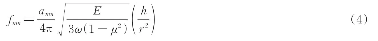
whereamnis a constant related to the vibrating modes of the diaphragm,ωis mass density of the diaphragm material.For the lowest natural frequency(a00=10.21)and based on the properties of fused silica,the frequency response of the diaphragm can be calculated as[27]

wheref00is in Hz.To ensure proper operation of the sensor,the natural resonant frequency of the diaphragm should be at least three to five times the highest working frequency.Due to the limitations of the test conditions,the maximum measurement frequency of the proposed all-silica pressure sensor is 2 kHz,so the natural frequency of the diaphragm should be above 10 kHz.
The sensitivity,pressure measurement range,and diaphragm natural frequency of the all-silica pressure sensor are determined by the effective radius and thickness of the silica diaphragm.The sensitivity of the sensor increases as increasing the effective radius and decreasing the thickness of the diaphragm.However,the large effective radius and small thickness of diaphragm could result in smaller pressure measurement range and frequency response of the sensor.It is,therefore,necessary to comprehensively consider the overall size,sensitivity,pressure measurement range,and frequency response when designing the sensor.We can obtain the desired sensor size,pressure measurement range,sensitivity,and frequency response of the all-silica dynamic pressure sensor by flexibly designing the diaphragm radius and thickness of diaphragm.The diaphragm effective diameter,thickness,theoretical pressure measurement range,sensitivity and frequency response of the proposed all-silica dynamic pressure sensor are 2.55 mm,200 μm,72 MPa,829.6 nm/MPa,and 337 kHz,respectively.
2 Sensor processing technology
The MEMS fabrication process of the FP cavity,as illustrated in Fig.2.First,the prepared 2-inch silica wafer was cleaned by the chemical wet cleaning method,as shown in Fig.2(a).Then spin-coat LOR photoresist and AZ5214 photoresist on the cleaned silica wafer,as shown in Fig.2(b).Next,the coated silica wafer was put into the photolithography machine to realize reverse exposure and immersed in 3 038 developer solution for 1 minute.The thickness of the photoresist measured after development is about 2.5 μm,as shown in Fig.2(c).Further,50 nm Ti and 1.2 μm Al were evaporated on the developed silica wafer by electron beam evaporation equipment,as shown in Fig.2(d).Subsequently,the silica wafer was soaked in acetone solution for 2 hours.Since the thickness of the photoresist was about 2.5 μm,the evaporated metal was about 1.2 μm,and the photoresist was easily soluble in acetone,so the area with photoresist was peeled off from the silica wafer and realizing the patterning of the silica wafer using metal as a mask layer,as shown in Fig.2(e).
Further,the silica wafer was put into the NLD-570 etching machine for batch etching of the FP cavity.Since there was no accurate silica etching rate,the cavity depth was measured with a step profiler after 10 minutes of etching,and it was found that the etching rate of silica was about 0.5 μm/min.Therefore,the etching time was set to 30 minutes,the diameter of the etching FP cavity was about 2.55 mm,and the depth was about 15 μm,as shown in Fig.2(f).Finally,the remaining Ti and Al metal mask layers after etching were removed with Ti etching solution and Al etching solution to obtain a silica wafer etched with a FP cavity array,as shown in Fig.2(g).
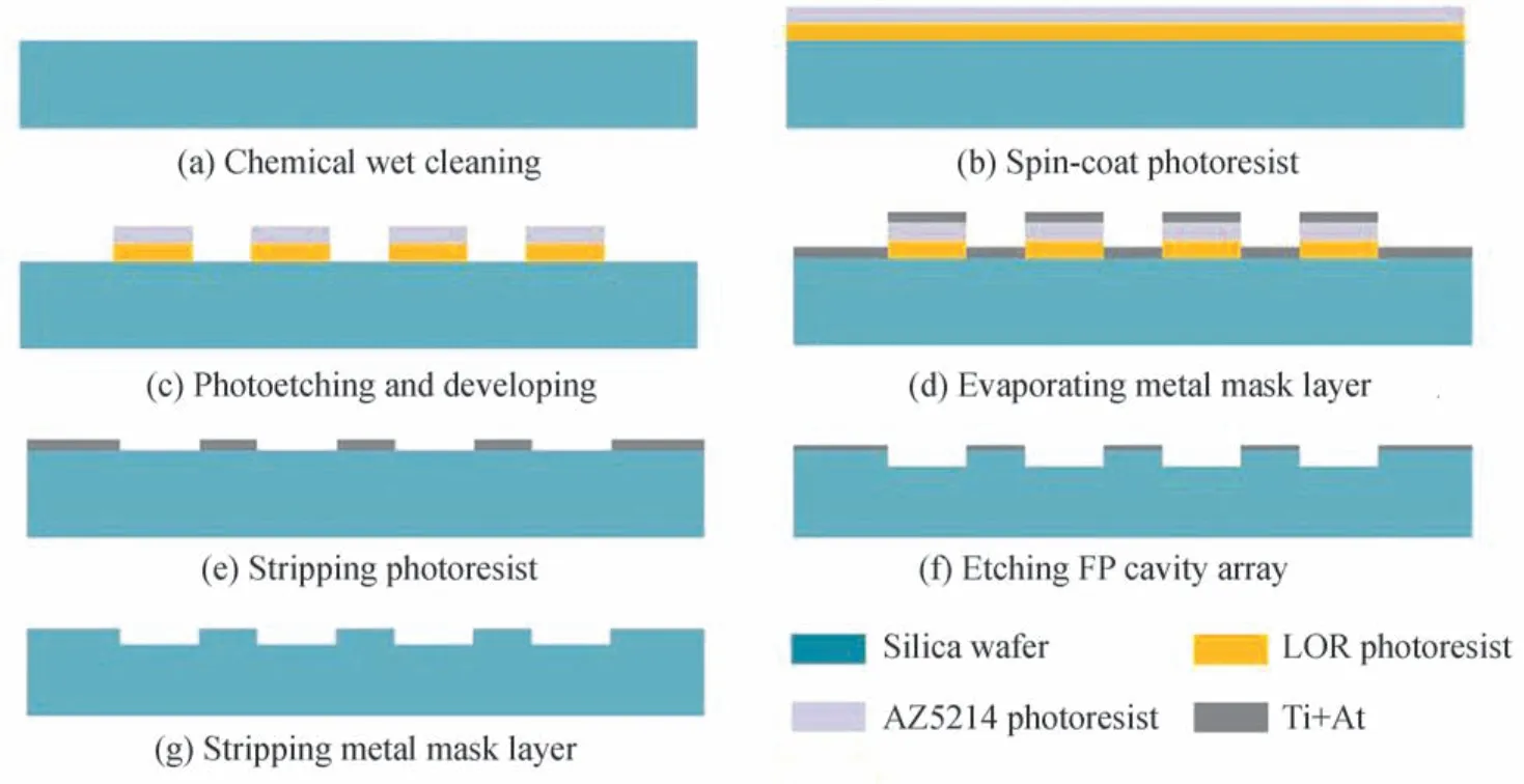
Fig.2 FP cavity MEMS etching process flow chart
The all-silica fiber-optic FP dynamic pressure sensor comprises a silica sensor head,an HST,and a goldcoated MMF.Among them,the sensor head is composed of a silica sensitive diaphragm,a silica cavity,and a silica pedestal.The proposed sensor heads are batch-fabricated via the MEMS technique and the three-layer silica direct bonding technology.As illustrated in Fig.3,the fabrication process of the all-silica pressure sensor includes three primary steps: silica wafer high-temperature direct bonding,silica wafer precision micromachining,and optical fiber integration.
During the fabrication process,a double-side polished 2-inch silica wafer with a thickness of 2 mm and 0.2 mm are employed for the pedestal and diaphragm,respectively.First,the 2-inch silica wafer employed for the pedestal with through-hole arrays fabricated by the Computer Numerical Control(CNC)technology,the 2-inch silica wafer with the microcavity arrays etched by MEMS technique,the 2-inch silica wafer employed for the diaphragm were directly bonded by three-layer silica direct bonding technology(the bonding temperature was about 850°C,and the bonding pressure was about 6.5 MPa),as shown in Fig.3(a).The diameter of the cylindrical through-hole is 1.1 mm.The groove and the cavity are coaxial,and the distance between two adjacent groove elements is 5 mm.Thereafter,the cylindrical protrusion array was fabricated on another surface of the pedestal wafer by using the CNC technology,as shown in Fig.3(d).The diameter and height of the cylindrical protrusion are 2 mm and 1 mm,respectively,and the protrusion was coaxial with the through-hole.Next,the all-silica sensor heads were separated from the bonded wafer using laser ablation,as shown in Fig.3(b)and Fig.3(e).

Fig.3 Fabrication process of the all-silica pressure sensor based on the silica wafer
Finally,the sensor head is assembled with the HST and MMF by using the CO2laser.The diameter and height of the all-silica sensor unit are 4.6 mm and 2.4 mm,respectively.The end of the gold-coated MMF was cleaved flat and inserted into the HST.The gold-coated MMF and HST were fused using CO2laser welding technology.Similarly,the protruding structure and the HST were fused using the CO2laser fusion splicer.Thus,the fabrication of the all-silica fiber-optic FP dynamic pressure sensor was completed,as shown in Fig.3(c)and Fig.3(f).
3 Experimental results and discussions
To investigate the high-temperature static pressure performance of the all-silica pressure sensor,a test system was set up,as shown in Fig.4.The system includes a high temperature and pressure testing platform,a demodulator,and a Personal Computer(PC).Among them,the testing platform compromises a pressure and temperature control system,a high-temperature pressure tank,and an argon cylinder.In the testing platform,temperature and pressure can be independently controlled.The pressure control system controls the pressure in the pressure tank by adjusting the air intake valve and the air outlet valve,and the temperature control system controls the temperature in the pressure tank by adjusting the heating power of the heating wires.The maximum temperature and pressure of the testing platform are 800 ℃and 1 MPa,respectively.The demodulator is connected to the all-silica pressure sensor via a fiber optical connector and the FP cavity length can be demodulated by the cavity length demodulation algorithm.

Fig.4 Experimental setup of high-temperature static pressure test
The all-silica FP pressure sensor was evaluated under temperatures ranging from room temperature(23 ℃)to 800 ℃,with increments of 100 ℃.At each temperature step,the all-silica pressure sensor was tested from approximately 0 MPa to 1 MPa,with increments of 200 kPa.When performing the pressure test,the pressure was kept constant for 2 min at each pressure point in order to record the cavity length more accurately.Fig.5(a)shows the cavity length of the all-silica pressure sensor with respect to the pressure at temperatures from 23 ℃to 800 ℃.It can be concluded that the FP cavity length of the all-silica pressure sensor varies linearly with the pressure at each temperature,and the nonlinearity at 800 ℃is 1.13%.

Fig.5 High-temperature static pressure experimental results of the proposed all-silica fiber-optic pressure sensor
Meanwhile,it can be seen from Fig.5(a)that the starting point position and slope of each fitting line are different at different temperatures.The difference in the starting point position of the fitting line is caused by the temperature drift of the sensor's FP cavity length resulted from the thermal expansion of the silica material.The initial cavity length and temperature are fitted with cubic curves and the R-square value is 0.97,as shown in the blue curve in Fig.5(b).It can be seen from the Fig.5(b)that the initial cavity length of the sensor gradually increases with the temperature increases,and the all-silica fiber-optic pressure sensor has an ultralow temperature drift coefficient of about 0.069 nm/℃.The sensitivity and temperature are fitted with cubic curves and the R-square value is 0.98,as shown in the red curve in Fig.5(b).The red curve shows that the pressure sensitivity decreases with an increase in temperature;this is caused by the intrinsic variation in the Young's modulus of silica at different temperatures.In addition,the all-silica pressure sensor has a pressure sensitivity of 801.84 nm/MPa at room temperature(23 ℃),which is similar to the theoretically calculated results.
To investigate repeatability and stability,the all-silica fiber-optic pressure sensor was evaluated from approximately 0 MPa to 1 MPa at increments of 200 kPa with the temperature of 23 ℃,400 ℃,and 800 ℃,as shown in Fig.6(a).During the experiment,one pressure increasing and decreasing test was defined as one pressure cycle,and three pressure cycle tests were carried out at each temperature.Based on the increasing and decreasing pressure conditions at 23 ℃,400 ℃,and 800 ℃,it is found that the all-silica fiber-optic pressure sensor shows good repeatability at different temperatures,good pressure-measuring performance at high temperatures,and the maximum repeatability error is 1.6%.To further test the stability of the all-silica fiberoptic pressure sensor in a high-temperature environment,the FP cavity length were tested under 800 ℃and 1 MPa and the test time was 60 min.The demodulated values of the sensor's FP cavity length were recorded with increments of 2 min.The results of stability test are shown in Fig.6(b).Obviously,the all-silica fiber-optic pressure sensor has good stability and the maximum fluctuation in the FP cavity length is approximately 11 nm,which was calculated by the maximum and minimum value of the recorded cavity lengths.This may be caused by the unstable pressure in the pressure tank and the system errors of the equipment.
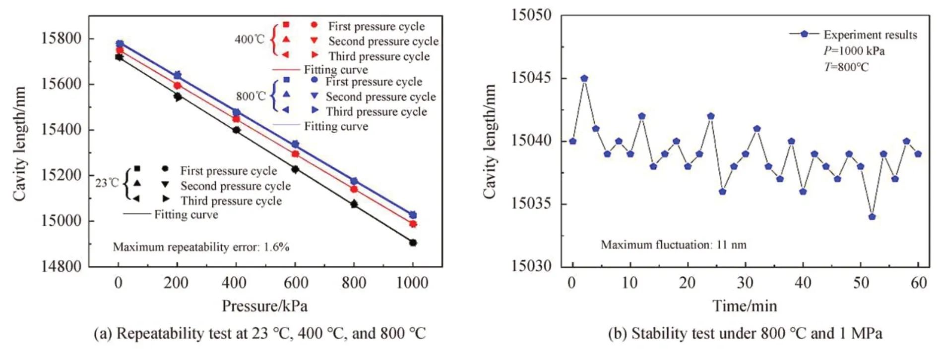
Fig.6 Repeatability and stability experimental results of the proposed all-silica fiber-optic pressure sensor
To measure the dynamic characteristics of the all-silica fiber-optic FP dynamic pressure sensor,the roomtemperature dynamic pressure test was carried out on the all-silica fiber-optic FP dynamic pressure sensor and the standard piezoelectric sensor (CYG401F,Kunshan Shuangqiao Sensor Measurement and Control Technology Co.,Ltd,China)at the same time on the sinusoidal pressure generator(LAISEN LS-ZX7M,Suzhou Dina Precision Equipment Co.,Ltd,China).The all-silica fiber-optic dynamic pressure sensor and the standard piezoelectric sensor were installed opposite to each other on the sinusoidal pressure generator,so that they had the same dynamic pressure environment,and the output dynamic pressure frequency of the sinusoidal pressure generator was set to be about 2 kHz.The dynamic pressure test result of standard piezoelectric sensor is shown in the blue waveform in Fig.7(a).The dynamic pressure test result demodulated by the dynamic cavity length demodulation algorithm[28]of the all-silica fiber-optic dynamic pressure sensor is shown in the red waveform in Fig.7(a).The pressure waveform measured by the all-silica fiber-optic FP dynamic pressure sensor and the standard piezoelectric sensor are very similar in amplitude and phase.The frequency response of the all-silica fiber-optic FP dynamic pressure sensor is in good agreement with the standard piezoelectric sensor,as shown in Fig.7(b),which indicates that the proposed all-silica fiber-optic FP dynamic pressure sensor has good dynamic response characteristics.
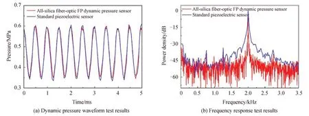
Fig.7 Room-temperature dynamic pressure experimental results of the proposed all-silica fiber-optic pressure sensor
4 Conclusion
In this paper,we have realized the high-consistency and batch-production of the all-silica fiber-optic FP dynamic pressure sensor heads with ultralow temperature coefficient using the MEMS technique and the threelayer silica direct bonding technology,which significantly reduced the variations in the sensor heads and the processing costs.The all-silica adhesive-free integration of sensor head and gold-coated MMF was realized by the CO2laser,which improves the stability of the sensor and allows the sensor to have an ultralow temperature coefficient (about 0.069 nm/℃) in high temperature environments.High-temperature static pressure experimental results show that the proposed all-silica fiber-optic pressure sensor can function under the temperature range from 23 ℃to 800 ℃with the nonlinearity of approximately 1.13% at 800 ℃and exhibited good linear response to pressure at high temperatures.Room-temperature dynamic pressure experimental results show that the proposed all-silica fiber-optic pressure sensor can function under the 2 kHz dynamic pressure environment and exhibited good dynamic pressure response characteristics.Furthermore,the frequency response of the all-silica fiber-optic pressure sensor is in good agreement with the standard piezoelectric sensor.We believe that the proposed all-silica fiber-optic FP dynamic pressure sensor will find broader and more promising applications in dynamic pressure measurement fields at high temperature and extreme environments due to its low cost,small size,batch-production,and ultralow temperature coefficient.
