A new model for the expansion tube considering the stress coupling:Theory, experiments and simulations
2022-07-27WuZhangZhang
M.Z. Wu, X.W. Zhang, Q.M. Zhang
State Key Laboratory of Explosion Science and Technology, Beijing Institute of Technology, Haidian District, Beijing,10081, China
Keywords:Expansion Circular tube Stress coupling Strain hardening Energy absorption
ABSTRACT Based on the two-arc profile assumption, the expansion deformation and energy absorption of circular tubes compressed by conical-cylindrical dies were reconsidered. First, the deformation of the two arcs was analyzed independently and an improved model denoted as Model-I was established. Then, by further involving the coupling between the bending moment and membrane forces, a more elaborate model, i.e., Model-II was developed. Afterwards, experiments and simulations were conducted to verify the models, which show that, compared with previous theoretical models, Model-II could not only capture the prominent features of the deformation, but also improve the prediction accuracy of the steady driving force significantly. By means of this model, it was found that the critical semi-conical angle, which makes the driving force minimum, increases with the increase of the friction coefficient,expansion ratio as well as the radius/thickness ratio of the tube. And, the energy dissipation due to stretching is always greater than that of bending,while the friction dissipation can account for the largest proportion at small semi-conical angle or large friction coefficient. At a certain friction and die conditions,the specific energy absorption of expanded tubes can be much higher than that under progressive collapse mode.
1. Introduction
When the military vehicles are subjected to the attack of bombs or landmines,or during the crash of helicopters,the structures and passengers will suffer highly-intensive impact loadings.In order to improve their survivability under these situations, the energy absorption of the structures is very important.Among different types of structures,thin-walled circular tubes have high specific strength and stiffness,and can serve as excellent energy absorbers[1].Under axial loading, there are four typical stable deformation modes,i.e.,progressive collapse, splitting-curling, internal/external inversion and expansion,respectively.The progressive collapse mode usually has a higher mean crush force in steady stage,and the stroke efficiency of the splitting mode is the highest.However,the loading of those two modes fluctuates greatly with an unpopular initial peak force [2-4]. On the contrary, the inversion and expansion modes have smooth loadings. Compared with inversion mode, expansion is easier to be realized and its energy absorption can be controlled[5,6]. Therefore, the energy absorption behaviors of expansion tubes have being attracted great attentions of engineers and researchers.
For the design of energy absorbers,Eddins[7]first proposed the expansion of the metallic tube as an energy absorbing device in spacecraft landing. Shakeri et al. [8] used rigid tubes to expand deformable tubes and investigated the influence of friction on their energy absorption. Yang et al.[9] studied the energy absorption of aluminum tubes compressed by conical-cylindrical dies, and showed that there are three deformation modes which are T-C,W-C and W-CC modes.Choi et al.[10]studied the effects of impact velocity and discussed the friction dissipation with numerical calculation. Yao et al. [11] adopted numerical simulation and adaptive response surface method to optimize the energy absorption of expansion tubes.

Nomenclature r0, Dout, h0 initial median radius, outer-diameter and wall thickness of tube, respectively L length of meridian of tube r, h median radius and wall thickness of tube at expansion region from A to B rd, Dd radius and diameter of the cylindrical part of die,respectively rcr the critical radius of die being the transformation point from the small die mode to large die mode Large die mode β =α and ΔS > 0 (Fig. 2(a))Critical die mode β =α and ΔS = 0 (Fig. 2(b))Small die mode β<α and ΔS = 0 (Fig. 2(b))rb, rc the median radius of tube at the positions B and C,respectively hb, hc the wall thickness of tube at the positions B and C,respectively b1, b2 curvature radius of the arcs AB and CD (or BC in the small die mode), respectively r2 the finial median radius of expanded tube r2’ the finial median radius of expanded tube when considering the springback of the deformation α,β semi-conical angle of die and inclined angle of tube wall which contacts with die surface, respectively Y,σ0.2 yield stress of material σu ultimate stress of material E elastic modulus ρ density B, n strain-hardening modulus and hardening exponent of material, respectively εe,σe equivalent strain and stress, respectively v0 velocity of die vf the sliding velocity of tube wall relative to die surface ˙E∅ ˙Eb plastic dissipation by stretching and bending,respectively ˙E1 ˙E2 and ˙E3 plastic dissipation rate in the stage AB, BC and CD, respectively μ friction coefficient Ff friction force ˙Ef friction dissipation rate F driving force Fs steady driving force f normalized steady force Fs/(2πr0h0Y)N0, M0 limit membrane force and bending moment per unit length, respectively Nz N∅ membrane force along the meridional and circumferential direction, respectively Mz bending moment along the meridional direction εz, ε∅, εx the normal strains along the meridional,circumferential and thickness directions,respectively x distance between a generic point and the neutral axial of tube along the thickness direction (-h/2≤x ≤h/2)αcr the critical semi-conical angle of die making the steady force minimum S stroke of die St stroke of die reaching the initiation of steady status l the initial length of the effective deformation region of tube SEA the specific energy absorption
Different from energy absorption, expanding is also an important forming process for tubular parts,which is called“flaring”[12].In this area,researchers are more concerned about the deformation and instability of the tubes, and a minimum driving force is preferred.For example,Lu et al.[13]analyzed the flaring ratio and end strain-rate of tubes in the tube flaring process.Fischer et al.[14]derived an analytical approach to determine the stress and strain fields as well as the force required for driving the expansion.Different instability modes, such as wrinkling, local buckling and fractures during the flaring process,and the controlling conditions were also studied [15,16].
In the previous studies, there are mainly three kinds of theoretical methods to analyze the deformation and the steady force of expansion tubes, which are stress equilibrium method [8,17-20],shell theory [21] and energy method [22], respectively. The stress equilibrium assumed that the expanding section of the tube was purely conical, then analytical models for the steady driving force was derived by yield criterions and stress equilibrium. Since the bending transition zone between the conical and cylindrical is not taken into account, this method is suitable for the cases with long conical section.In the shell theory method,the expanded tube was considered as a cylindrical shell, and based on the assumptions of small deflection, constant wall thickness and uncoupling of the bending moment and membrane force, the steady force and configuration of the expanded tube can be obtained by solving the equilibrium equations. However, this method is only suitable for the cases with small expansion ratio. Different from the above methods,the energy approach proposed by Liu et al.[22]was based on the configuration that the profile of the expansion tube as two arcs connected by a straight line, which is closer to the actual deformation profile of expanded tube.However,in this model,the two arc-sections were assumed to have the same curvature radius,and the coupling of the bending moment and membrane forces as well as thickness variation weren't also considered, which influence the precision of the theoretical model.
In this paper, based on two-arc profile assumption, the expansion deformation and energy absorption behaviors of thin-walled circular tubes axially compressed by conical-cylindrical dies were reconsidered to establish a new analytical model,in which the two arc zones were processed independently,and the yielding function consisting of the membrane forces and the bending moment were introduced to study the effect of the stress coupling. Also, the influences of strain hardening and thickness variation were considered.Then,the steady force and final radius of the expansion tubes predicted by the models were compared with experimental and numerical results to show their validity.Moreover,the influences of the geometry of the die, the friction coefficients, and the energy absorption due to different dissipation mechanisms were discussed.Finally,the specific energy absorption of the circular tubes in expansion mode was compared with those under splitting and progressive collapse modes.
2. Theoretical modeling
2.1. Description and assumptions
If a circular tube is axially compressed by a conical-cylindrical die with semi-conical angle α and outer radius r, the typical process can be illustrated by Fig.1.After the tube initially contacts the die, the tube wall will bend and expand outwards as shown in Fig.1(b). When the tube end becomes tangential to the surface of the die, the contact changes to be surface contact as shown in Fig.1(c). Then, with the compression processing, the shape of the section AB keeps the arc shape, and the contact area becomes longer.When the radius of the tube end at point E is larger than r,the section CE will not be able to contact the die as shown in Fig.1(d).Finally,when the displacement of the die is enough large,the deformation will become stable as described by Fig.2(e).In the stable stage, the tube wall will mainly experience three expansion stages,which are two curved sections AB,CD and a straight section BC.

Fig.1. Typical deformation process of tube expansion.
It should be pointed out that the above deformation mode is based on that ris enough large which was defined as “large die mode” by Liu [22]. If the radius ris equal to or smaller than a critical value r, there will be no straight section and the die only contacts tube wall at point B. These two cases are defined as“critical die mode”and“small die mode”[22],while the critical die mode can be considered as a special case of small die mode.
The configurations of the tube wall with large die and small die modes are illustrated in Fig.2.Assume the initial median radius and thickness of the circular tube are rand h, and the velocity of the die is v. During the expansion process, the median radius and thickness become r and h,respectively.In the theoretical modeling,it is assumed that the die is rigid, the material of the tube is incompressible and the arc-length of the tube wall along the meridional direction remains unchanged during the deformation process. Then, according to the volume conservation of material,we have,

Fig. 2. Deformation of the tube wall: (a) large die mode; (b) small die mode.


2.2. Modeling without strain-hardening and stress coupling
First,the material is considered as rigid perfectly-plastic and the coupling between the stresses in the circumferential and meridional directions is ignored and the expansion deformation at the steady stage is analyzed by energy method.
2.2.1. Large die mode
When the diameter of the die is large enough, i.e., r>(r-(hcosα)/2),where ris the median radius of the tube at point B as shown in Fig. 2(a), the expansion process of the tube will experience three stages sequentially,i.e.,AB,BC and CD.According to the analysis in section 2.1, the stages AB, BC and CD are formed independently. Thus, the deformations in the three stages will be analyzed individually.
a) During the stage AB,the tube will be first bent from straight to
be curved at the point A. For simplicity, the curvature radius of the section AB is assumed to be constant,which is denoted by b.Then,from A to B,the tube wall only stretches circumferentially,while at the point B,the tube wall is quickly bent to be straight along the meridian direction.

Then, we have,
Then, the driving force of the expansion tube at the steady deformation stage can be obtained by,

Fig. 3. (a) Stress status of a tube wall element; (b) the yielding surface.

The final middle radius of the tube after expansion is,

2.3. Modeling with stress coupling
In the above analysis, the coupling between the stresses in the circumferential and meridional directions is ignored, so that the energy dissipation may be over predicted. In reality, the stress status in a typical element of the tube wall under expansion is shown in Fig. 3(a), and the yielding of the material is jointly determined by the axial compressive membrane force N, the circumferential membrane forces N,and the bending moment M.In this section,the influence of the stress coupling will be taken into account to improve the above model. As shown in Fig. 3(b), the yielding function consisting of the membrane forces N,N,and the moment M,was established by Tresca yield criterion[23],in which the yielding surface is defined by,

When the plastic deformation occurs, for a give axial compressive membrane force N/N, the corresponding circumferential membrane force Nand bending moment Mwill be situated on the intersection of the yielding surface with the plane N/N.For the sake of clarity,four intersections with different N/Nare projected to the N-Mplane as shown in Fig.4(a).It is seen that the type of yield locus is essentially a rectangle with the corners rounded off by the parabolic arc. With the decrease of N/N(<0), the vertices of the locus will slide down along the parabolic arcs IJK and IJ’K respectively. For simplify, the parabolic arc is ignored, and the complete rectangle is adopted to approximate the yield locus, as the dotted line in Fig. 4(a). Then, when N/N< 0, the yielding function about the locus can be given as follows

Notably, the compressive membrane force Nhas a great influence on the position of the yield locus on the plane N-MHere,the distribution of Nrelated to the axial force is discussed in detail.To ensure the force balancing along the meridional direction, Nis continuous.In the steady stage of the expansion,the driving force F is transmitted by the region BC to the tube wall as shown in Fig. 4(b). If ignore the influence of the inclined angle of the tube wall,the axial force on any wall section below B remains constant,and Nin this region can take the value F/(2πrh). For the section from B to C,the axial force will decrease due to the decrease of the contact area, and the variation of that can be approximated as a linear function. Hence, the distribution of Nalong the meridional direction can be given as depicted in Fig. 4(b).
According the Drucker's stability postulate, the generalized strain rate vector associated with plastic flow must be normal to corresponding generalized stress point on the yield locus as the arrow in Fig. 4(a). Due to the assumption that the curvatures keep unchanged at the arcs AB and CD, thus the possible flow mechanism in the plane N-Mcan be as the followings,


Fig. 4. (a) The yielding locus on the plane Nφ-Mz; (b) the distribution of Nz along the meridional direction.

For the small die mode, α should be replaced by β. Compared with the model without considering the stress coupling, it is distinct that the deformation behavior of the stage AB is affected by the driving force F. Since it's difficult to save the above physical equations directly, an iterative method is adopted as follows:
1) First, by mean of the previous model without the stress coupling, we get the initial solution for Fand f;
2) Substitute f into Eqs.(34-37)to obtain F.Then,a new value for f could be obtained.
3) After several iterations of step-2, the value of f will gradually approach its exact solution.
To examine the influences of different models,in the subsequent sections,the rigid-plastic model developed in section 2.2 is denoted by Model-I, while the improved model containing the effect of stress coupling is described by Model-II.
2.4. Effects of strain-hardening
In the above models, the tube wall is assumed to be perfectlyplastic. However, in real situations, most materials have remarkable strain hardening.Therefore,in this section,isotropic hardening with power law is adopted to approximately describe the stressstrain relationship of the material as below,


3. Validation by experiments and numerical simulations
3.1. Experimental details and results
To verify the theoretical models, expansion experiments were first conducted, in which mild steel and aluminum alloy circular tubes labeled by C45 and AA-6061 were employed. Typical specimens are shown in Fig. 5(a), whose outer diameter and thickness are D= 52 mm and h= 2.1 mm, and the length of the tubes is L=200 mm.Fig.5(b)plotted the quasi-static tensile test results of the two materials,showing that their yield and ultimate stresses are σ=540.9 MPa and 185.5 MPa,σ=681.9 MPa and 237.8 MPa,respectively. Also, the ultimate tensile strains of the two materials are about 0.16.After fitting the stress-strain relationships by power law, their mechanical property parameters are listed in Table 1.
As shown in Fig.6,the tube was axially compressed by a conicalcylindrical die with diameter Dand semi-conical angle α. Quasistatic tests were conducted using an MTS machine with crosshead speed 10 mm/min, and dies with D= 50-60 mm and α=10~40were used.Fig.7 shows the typical expansion process of a steel tube,revealing that this tube was successfully expanded.More details about the tests are listed in Table 2, where Fis the driving force at the steady compression stage.
The force-displacement curves obtained in the tests were plotted in Fig. 8. It reveals that with the increase of the displacement of the die,the driving force first increases quickly to a certain value. Then, after a weak drop, the driving force continues to increase until the steady stage, in which the driving force is almost constant.Denote the stroke and compressive force at the initiation of steady status by Sand F. It can be seen that for a given semiconical angle, the larger the radius of the die, the larger Sand Fwill be,while with the same r,the smaller the angle α,the longer Swill be larger.
In most tests, stable deformation can be generated. However,when the semi-conical angle and expansion ratio r/rwere too large, instability phenomena occurred. For the steel tubes, the ductile fracture occurred when α = 30and D= 55 mm, and the driving force dropped soon after fracture happened.Instead,for the aluminum alloy specimens with α = 30and D= 60 mm, stable expansion deformation still can be successfully generated;but that with the die radius D= 55 mm, when α increases to be 40,asymmetric buckling happens so that the force dropped after it reaches the first peak.
The steady force varies in a wide range with different semiconical angle and radius of the dies, and the variation of the steady driving force with respect to the conical angle is not monotonic. As shown in Fig. 8(b), the steady force of S-10-55 is higher than that of S-20-55.But for the cases A-20-55 and A-10-55,their driving forces are close to each other and much lower than that of A-30-55. It should be noted that, the driving force for the case A-30-60 approaches to the peak force of case A-40-55, in which progressive collapse mode occurs.

Table 1 Mechanical parameters for the two materials.
3.2. Validation of the theoretical model
First, the friction coefficient was estimated by comparing the theoretical and the experimental steady driving forces,as shown in Fig. 9, in which Model-II was adopted considering the strain hardening. It is seen that the friction coefficient has a great influence on the steady force.For the steel tubes,the friction coefficient is 0.05-0.2; while for the aluminum one,the friction coefficient is about 0.3-0.45.It is inferred that in the tests,the larger the steady force, the contact pressure between the die and the tube wall will be larger, causing the friction coefficient may increase.
Then, nonlinear finite element Code ABAQUS/Static was adopted, and the experimental data and numerical simulation were combined to verify the accuracy of the theoretical model. The geometric and material parameters listed in Tables 1 and 2 were used.Due to the axi-symmetry of the circular tubes,axi-symmetric model was developed as shown in Fig. 1, in which the die was considered as a rigid body. The contact between the die and the tube wall was defined as penalty contact with friction coefficient μ calculated by the theoretical model.
The comparisons between the numerical and experimental load-displacement curves are shown in Fig.10.For the cases,i.e.,S-10/20-55 and A-30-60, the large die mode occurs, and the small die mode happens at the case A-30-50. It can be found that excellent agreement between the numerical and experimental loading curves is obtained, verifying the accuracy of Model-II.What's more, for the case A-30-60, it can be seen that when μ is 0.45,the successful expansion deformation occurs,while at μ=0.5,the progressive collapse mode happens.

Fig. 5. Metallic circular tubes: (a) specimens; (b) true stress-strain curves.

Fig. 6. Design of expansion experiments.

Fig. 7. Expansion process of steel tube under a cone die with rd = 27.5 mm, α = 20°.

Table 2 Detail dimensions and test results.
3.3. Comparison with two previous theoretical models
Since in the previous studies, several models [20,22] had been proposed to predict the steady driving force.Here,the comparisons between these models and numerical results were conducted using the tube with r=24.95 mm and h=2.1 mm.For simplicity,elastic perfectly-plastic material, with Young modulus E=69.7 GPa and yield stress Y = 185.5 MPa,was employed.
Fig.11(a) illustrates numerical and theoretical steady force under different cases with r=27.5 mm and μ=0.1,which shows that with the increase of the semi-conical angle α, the steady force decreases first and then increases.There is a minimum value of the steady force when α is about 10-15.All the theoretical models can predict this tendency, while the predictions of Model-II are much best than those of other models, among which the predictions by Model-I and Liu's model are relatively larger, which is the result from the stress coupling is ignored causing that plastic energy dissipation is over-predicted.
Fig. 11(b) depicted the steady forces of expanded tubes with different friction coefficients,showing that the steady force almost increases linearly with the increase of friction coefficient.The slope of Model-II agrees with the numerical results well, but that from Yan's model is a little lower, while those from Liu's model and Model-I are a little higher. Besides, Fig. 11(c) shows that the relations between the steady force and die radius can be divided into two sections, which are corresponding to the small and large die modes,respectively.It can be seen that with the increase of r,the steady force in the small die mode increases more sharply than that in the large die mode. And, the predictions of Model-II are much closer with numerical results when r< 30 mm. But beyond r=30 mm,the predictions of Model-II are smaller than numerical results, which may be attributed to that with the increase of expansion ratio r/r,the plastic dissipation by compression in the meridian direction gradually increases, and cannot be ignored when r/r>1.2.Besides,Yan's model cannot reflect the transition from small die mode to large die mode. Correspondingly, the maximum inclined angles of the tube wall at different cases are also depicted in Fig. 11(d), which also shows that the prediction of Model-II is closer to the simulation data.

Fig. 8. Experimental results for the tubes at different cases: (a)C45; (b)AA-6061.
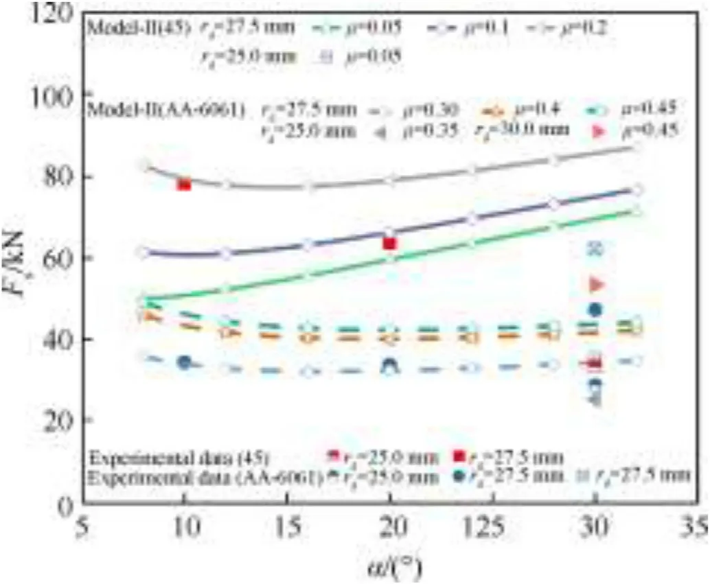
Fig. 9. Comparison of the steady forces from experimental and theoretical results. at different friction coefficient.
From simulation, the stress distributions along the thickness direction at three different positions from A to D are depicted in Fig.12, where x/h = -1/2 represents the inside of the tube wall. It can be seen that compared with the values of σand σ,the value of σis relatively smaller,and there is obvious coupling effect between σand σ.By integrating the stresses along the thickness direction,the corresponding membrane forces N(i = ∅, z) and the bending moment Mwere calculated to compare with the theoretical values as shown in Fig. 13(a). It can be seen that at the arc regions, the predications N/Nfrom Model-II are always larger than the numerical values, which is the result from the rectangle simplify as the mention above in section 2.3. And, the value of M/Mat the region CD is smaller than that from Model-II, which may be attributed to that the current model ignores the effect of the shear stress σand the elasticity of material. Overall, the comparison indicates that Model-II can well reflect the variation of N/Nand M/Malong the meridian direction.To further explore the range of application of Model-II, the steady forces from theoretical and numerical results at the cases with different α and hare compared in Fig.13(b), which shows that when α<30and h/r<0.14, the predications of Ffrom Model-II are in good agreement with simulation results.

Fig.10. Comparison of the experimental and numerical driving force-displacement curves: (a) S-10/20-55; (b) A-30-50/60.

Fig.11. Comparison of the steady force from the numerical and theoretical results:(a)rd=27.5 mm,μ=0.1;(b)α=20°,rd=27.5 mm;(c)α=20°,μ=0.1;(d)maximum inclined angle at different rd with α = 20.°.

Fig.12. Stress distribution along the thickness direction at the case α = 10°, h0 = 2.1 mm, rd = 27.5 mm and μ = 0.1.
For the “flaring” process, the final radius rare also concerned.The differences between the radius after expansion and its original radius, i.e., r-r, are plotted in Fig. 14, which shows that the predication by our model agree better with the numerical results than Liu's model. And, it should be noted that the experimental result is slightly smaller than those from Model-II, which may be result from the effect of the round fillet of die in the tests.

Fig.13. (a) Comparison of the stress coupling effect from the numerical and theorical results; (b) the steady forces at the cases with different thickness and semi-comical angle.

Fig.14. Comparison of the difference r2-r0 from theoretical, experimental and numerical results: (a) at different α with rd = 27.5 mm; (b) at different rd with α = 20° and 30°.
According to the above comparisons between the theoretical models and experimental as well as the numerical results,it can be seen that when α<30,h/r<0.14 and r/r<1.2,Model-II can not only predict the steady force of the expansion tubes well, but also give good evaluation of the final radius (or the gap r-r).
4. Discussions
4.1. Influences of the stress coupling
Since in Model-II, the yielding function, i.e., the coupling between the bending moment and membrane forces is considered,in this section,the influence of this effect on the curvature radiuses of the arc sections is examined. For comparison, the results from Model-I and Liu's model are also given.It is shown in Fig.15 that the curvature radius decreases with the increase of die angle. The curvature radius of the arc AB obtained by Model-I nearly coincides with that of section CD, which is slight smaller than the results of Liu's model. However, when the yielding function is considered in Model-II, the curvature radius of the arc AB will be significantly larger than that of the arc CD, which is equal to that of Model-I.

Fig.15. Curvature radiuses of the arcs at different die angle with r0/h0=11.9,rd/r0=1.1 and μ = 0.1.
Fig. 16 illustrate that the numerical curvature (κ = 1/b) of the deformed tubes along their meridian direction at two typical modes, showing that the curvature of the tube wall varies continuously along the meridian of the tube,and there are two segments with large curvatures at opposite directions, which are related to the transition sections CD and AB,respectively.Besides,at the two deformation modes, the maximum curvature in segment CD is significantly greater than that in segment AB,which means that the average curvature radius in section AB is larger than that in section CD. Compared with Liu's model, our theoretical Model-II can well reflect this phenomenon.
Since the steady force and final radius of the expansion tube greatly depend on the curvature radiuses of the sections AB and CD,it means that the differences between the Model-II and Liu's model are due to the consideration of stress coupling.
4.2. Analysis of the critical semi-conical angle
In this section,the critical semi-conical angle making the steady force minimum was further analyzed.By Model-II,the steady forces of the expanded tubes at different cases are calculated and plotted in Fig.17,where f is the normalized steady force by F/(2πrhY).As shown in Fig.17(a),for a given semi-conical angle,the steady force increases with the increase of the friction coefficient. When the friction coefficient is zero, f increases with the increase of α.However,if it is not zero,there will be a critical semi-conical angle α. And, the larger the friction coefficient, the larger the critical semi-conical angle will be.
Fig.17(b)shows the variations of f with respect to α at different expansion ratio r/r.It can be seen that αwith the increase of r/r. While, for low r/r, f keeps constant when α exceeds a certain semi-conical angle,in which the small die mode occurs.Moreover,Fig.17(c) depicts f at different radius/thickness ratio (r/h) and α,showing that αalso increases with the increase of r/h.
It should be noted that,for the energy absorbers with expansion tubes, the critical semi-conical angle should be avoided. Although the maximum steady force may occur at small α, e.g., α = 5and μ > 0.1, the energy absorption may not be highest, due to that the stroke Sis also large for small α as shown in Fig. 8. However, for flaring, the critical semi-conical angle is preferable.
4.3. Partition of energy dissipation
Based on Model-II, the energy dissipation due to stretching,bending and friction was also analyzed by comparing their contribution to the steady driving force as shown in Fig.18.In Fig.18(a),it is shown that,for a given μ,the larger α is,the smaller the friction dissipation will be.However,the energy dissipation of bending and stretching increases, and the energy dissipated by bending increases much more remarkable than that due to stretching. It can be seen that the reduction of friction dissipation is greater than the increment of plastic dissipation until α=α,which is the cause for the minimum steady force.
Fig.18(b)shows that with the increase of the friction coefficient,the friction dissipation significantly increases,while the stretching dissipations slightly decrease, and bending keep near constant.What’ more, Fig.18(c) illustrates that the larger r/ris, the larger the dissipation of stretching and friction will be,while the bending dissipation slightly decreases. On the whole, it is found that, the stretching dissipation is always greater than the bending dissipation,and the friction dissipation accounts for the largest proportion at small α or large μ.
4.4. Specific energy absorption
To compare the energy absorption capability of the tubes with different dies, the specific energy absorption SEA is used as below,

Where S is the stroke of the die, l is the length of the effective deformation region,the material density ρ for steel and aluminum alloy are 7800 kg/mand 2700 kg/m, respectively.
As listed in Table 2,similar to the variation of the steady driving force,SEA also varies in a large range depending on the semi-conical angle and radius of the die as well as the friction coefficient. The aluminum alloy tubes dissipate a larger amount of the energy per unit mass than steel ones. Most notably, for the case A-30-60, SEA can even reach 54 J/g, which is much larger than 37.1 J/g of aluminum tube with Y = 198 MPa and r/h=12.2 at progressive collapse mode [3],and 15 J/g of aluminum tube with Y = 180 MPa and r/h= 13.5 at splitting mode [4], showing that the energy absorption potential of tubes can be most exploited by expansion deformation.However,it should be noted that the space utilization efficiency of the expansion mechanism is less than 50%,due to the expanded region of the tube will wrap the die as showed in Fig.7.To alleviate this shortcoming, hybrid mode combining expansion deformation with splitting or progressive collapse mode can be adopted [24,25].

Fig.16. The curvature of the tube wall along its meridian direction: (a) large die mode (α = 10°, rd = 27.5 mm); (b) small die mode (α = 20°, rd = 24.7 mm).

Fig.17. Normalized steady force at different cases: (a) r0/h0 =11.9, rd/r0 =1.10; (b) r0/h0 =11.9, μ = 0.15; (c) rd/r0 = 1.10, μ = 0.15.

Fig. 18. Energy partition of stretching, bending and friction: (a) r0/h0 = 11.9, rd/r0 = 1.10, μ = 0.15; (b)r0/h0 = 11.9, rd/r0 = 1.10, α = 20°; (c) r0/h0 = 11.9, α = 20°,μ = 0.15.
5. Conclusions
Based on the two-arc profile assumption, the expansion behaviors of thin-walled circular tubes axially compressed by conicalcylindrical dies were reconsidered. First, the profile of the expansion tube in the transition zone was assumed to be two arcs connected by a straight section,and a theoretical model named Model-I was developed by independently analyzing the two arcs,also the thickness variation was taken into account. Correspondingly, the critical die radius,the curvature radiuses of the arcs and the steady driving force were derived.Then,this model was further improved to be Model-II considering the coupling between the bending moment and membrane forces as well as the strain-hardening effect.
Afterwards, some tests and simulations were carried out to verify the theoretical model, good coincidence was obtained between the experiment data and the theoretical prediction as well as simulation results. Compared with Liu's model and Yan's model, it was seen that Model-II further captures the prominent features of the deformation profile, and the accuracy of the steady force prediction is improved significantly. It should be noted that the most applicable range of this model is the region with α < 30, h/r<0.14 and r/r< 1.2. By this model, it was found that with the friction, the minimum steady force will occur at a critical conical angle α,which increases with the increase of friction coefficient μ,the expansion ratio r/rand the radius/thickness ratio r/h. The energy dissipation of the expansion tubes mainly comes from three mechanisms, i.e., stretching, bending and friction. The stretching dissipation is always greater than the bending dissipation,and the change of the die conical angle has the greatest influence on the bending dissipation, the friction dissipation can account for the largest proportion at small die conical angle or large friction coefficient.
It is interesting that at a certain combination of expansion ratio and semi-conical angle, the steady driving force can approach to the empirical peak forces under progressive collapse mode. However, too large expansion ratio, semi-conical angle or friction coefficient may induce instability deformations.Considering that the space utilization efficiency of expansion tubes is a little less than 50%, to increase this efficiency, deformation mode combining expansion and splitting is a good choice.
The authors declare that they have no known competing financial interests or personal relationships that could have appeared to influence the work reported in this paper.
This research was funded by the National Key R&D Program of China with Project No.2016YFC0801200. Their financial support is greatly thanked by the authors.
杂志排行
Defence Technology的其它文章
- Influence of carbide ceramic reinforcements in improving tribological properties of A333 graded hybrid composites
- Effects of particle size and content of RDX on burning stability of RDXbased propellants
- Analysis of temporal and spatial distribution characteristics of ammonium chloride smoke particles in confined spaces
- Experimental investigations on small-and full-scale ship models with polyurea coatings subjected to underwater explosion
- Numerical simulation of radiated noise during combustion of energetic materials in a closed bomb
- Influence of structure and material on the vibration modal characteristics of novel combined flexible road wheel