Influence of structure and material on the vibration modal characteristics of novel combined flexible road wheel
2022-07-27YaojiDengYouqunZhaoFenLinLiguoZang
Yao-ji Deng , You-qun Zhao , Fen Lin , Li-guo Zang
a College of Mechanical Engineering, Yangzhou University, Yangzhou 225127, China
b College of Energy and Power Engineering, Nanjing University of Aeronautics and Astronautics, Nanjing 210016, China
c School of Automobile & Rail Transit, Nanjing Institute of Technology, Nanjing 211167, China
Keywords:Flexible road wheel Orthogonal experimental design Vibration modal Tracked vehicle Finite element analysis
ABSTRACT Aiming at the independent development of tracked vehicles, it is urgent to improve its mobility, passability and ride comfort,a new type of flexible road wheel with a“wheel-hinge-hub”combined structure is proposed in this study.The vibration model characteristics of the flexible road wheel were studied by the combination of numerical simulation and experiments. The superelasticity of rubber is obtained through uniaxial tensile experiment of the material and a detail three-dimensional nolinear finite element model of the flexible road wheel is established through finite element software ABAQUS. The free vibration equation of the flexible road wheel is solved by Lanczos vector direct superposition method,and its predicted modes and natural frequencies are compared with experimental results,which verifies the accuracy and reliability of the established finite element model. On this basis, the effects of various key structural or material factors on the natural frequencies of the flexible road wheel are studied using orthogonal experimental design method.Besides,the vibration modal characteristics of the flexible road wheel are also compared with those of the rigid road wheel. The research results provide a theoretical basis for the vibration and noise reduction of flexible road wheel.
1. Introduction
Different from wheeled vehicles, tracked vehicles use a track driving system.The crawler can be regarded as a road carried by the vehicle.It is easy to pass on roads with lower bearing capacity and has greater traction.It has strong cross-country passability and can drive in areas with no roads,deep snow and swamps that cannot be used by wheeled vehicles[1].Therefore,it has been widely used in the fields of military,construction,forestry,mining and agricultural engineering. Especially in the military, high mobility has become one of the main goals of modern tracked vehicle design and research.As the main moving parts of the tracked vehicles,the road wheel directly bears the static and dynamic loads between the body and road,and plays the role of supporting the body,mitigating the impact and isolating the vibration and noise. Therefore, the dynamic characteristics of the road wheel have a very important impact on the handling stability,ride comfort and fuel economy of tracked vehicles [2].
Currently, the traditional road wheel for tracked vehicles is usually a solid wheel plate wrapped with rubber, and has many shortcomings such as heavy weight,low load-bearing efficiency,and poor vibration damping effect,seriously limiting the further improvement of lightweight, maneuverability, riding comfort and passability of tracked vehicles. Aiming at the above disadvantages of the traditional road wheel, many research scholars and institutes have conducted some research on the structure and materials of road wheels[3-5]. Although these research results have achieved some beneficial effects, they have not fundamentally broken through the solid structure of traditional rigid road wheels. From the perspective of new configuration design, we proposed a new type of flexible road wheel with a composite structure of “wheel-hinge-hub”, using bendable hinge groups to flexibly connect the wheel disc and the rim,not only has inherent advantages in lightweight design,but also improves the load-bearing efficiency of the road wheel and the adhesion performance between the road wheel and track[6-10].
It has long been recognized that the modal characteristics of flexible road wheels directly affect the ride comfort, ride comfort,and vibration and noise of the vehicle. Therefore, the research on the vibration modal characteristics of road wheels is particularly important, which can help us to design the structure and material of flexible road wheels, improve the modal characteristics of road wheels more efficiently, and better match the whole vehicle. In addition,studying the modal characteristics of flexible road wheels is also the prerequisite and basis for optimizing suspension and road wheel systems,as well as vibration and noise reduction.
In the early analysis of the vibration characteristics of tires, the modal and vibration transfer characteristics of tires have been studied by method of experiment[11-13],but this method requires enormous time and cost and has rarely been adopted. To reduce costs and improve efficiency, the tire was usually simplified to an elastic ring with an elastic foundation [14-18] or a simple finite element model [19-21] established using a membrane unit and a shell unit. However, this simplification does not characterize the complex structure of the tire and the nonlinearity of the material,which limits its value in practical engineering applications.
With the development of computer and numerical simulation technology,the finite element method(FEM)which can accurately simulate tire geometry, load and material characteristics, and provide very useful information has been widely used to analyse the tire performance. Sakthivel Palanivelu et al. [22] proposed a novel method combining the explicit finite element analysis and operational modal analysis for defining the modal parameters of a rolling tire. Guo, H [23] described the development of a detailed finite element(FE)model of an aircraft test tyre for investigating its performance and assessing its safety criteria. E.O. Bolarinwa [24]developed a detail three-dimensional finite element tyre models for investigating the tyre vibration behaviour. I. Lopez et al. [25]established a finite element(FE) model of the tyre to calculate the dynamic response of a rolling tyre. Moisescu A R [26] developed a complex finite element model of 9.00R20 and 9.00-20 truck tyres for investigation of modal behaviour of tyres without road contact.Negrus E [27] presented a finite element model which takes account of tyre structure, constituent anisotropy and non-linear properties of materials for modal analysis. X.C Jin [28] developed a detailed finite element model of a Non-pneumatic tire and studied the static and dynamic behaviors of NPTs with different honeycomb spokes. Wei C [29] established a finite element model of a tyre based on the measured material and geometry properties and studied the effect of structural layup and material properties on the relaxation length by the design of experiment (DOE) method.
To the best of our knowledge,the past research mainly focused on the vibration modal characteristics of pneumatic tires for automobiles, but the studies on the dynamic analysis of the flexible road wheels for tracked vehicles were rarely seen. In addition, the traditional parameterization research method of tire modal characteristics is time-consuming and laborious. Therefore, this study combines finite element and experimental design methods to efficiently study the influence of structure and material on the vibration modal characteristics of the novel flexible road wheel.Firstly, the superelasticity model of rubber material were determined by uniaxial tensile test and a precise 3-D finite element model of a new type of flexible road wheel was established using the large-scale general finite element software ABAQUS. Then, the accuracy and reliability of the finite element model was verified by modal experiments. Next, the modal characteristics of the flexible road wheel were studied and compared with those of the rigid road wheel. Finally, the effects of various significant factors, including the number of hinge groups,the cross sectional area of elastic rings,the thickness of rubber and the elasticity modulus of hinge group,hug,and elastic rings on the natural frequencies of the flexible road wheel were studied.The research results revealed the relationship between the vibration characteristics of the flexible road wheel and the structure and material characteristics and provide a theoretical basis for solving the noise, vibration and comfort problems encountered in the process of matching the tracked vehicle with flexible road wheels.
2. Structure and working principle of rigid and flexible road wheel
2.1. Structure
Traditional rigid road wheels are generally composed of four parts: flange, rim, spokes and hub. According to the degree of vibration reduction, the types of road wheels can be divided into three types: all-metal (no vibration reduction), internal vibration reduction and external vibration reduction (outer rubber ring).Among them, the external vibration-damping road wheels are the most widely used,as shown in Fig.1(a).The rims of the road wheels are covered with rubber aprons. The structure is simple, easy to implement, has the function of vibration isolation and noise reduction,and helps to improve the driving stability of the vehicle.The effect of road wheels on tracked vehicle is mainly reflected in rolling resistance, ground pressure, maximum speed, lightweight,ride comfort,and heat dissipation.As the speed of tracked vehicles increases,the requirements for road wheels are getting higher and higher. Traditional road wheels have many shortcomings, which limit the further performance improvement of tracked vehicles.
The flexible road wheel breaks the structure configuration of the rigid road wheel. Its main components include: elastic ring,detachable hinge group, hub, combination card, as shown in Fig.1(c). The elastic ring replaces the rim part, and the traditional wheel disc is replaced by the hinge group and hub structure. Five elastic rings are combined together by twelve combination cards.The outer surface of the elastic rings are encapsulated with the rubber layers, and the elastic outer ring is formed after vulcanization.Compared with the connection mode between the rubber and ring of the rigid road wheel, the flexible road wheel embeds the rubber and elastic ring into each other using the principle of bionics, which can effectively prevent degumming and suitable for high-speed driving.The elastic outer ring and hub are connected by a number of hinge groups uniformly distributed along the circumference. The number and length of the hinge groups can be freely chosen to meet the requirements of vehicle adaptability to the maximum extent.
This structure has two advantages over the rigid road wheels.On the one hand, to reduce the wheel weight and improve structural strength, different new materials could be used in different parts according to functions needs.On the other hand,the ellipticlike deformation and bending hinge group increases the flexibility of the flexible road wheel and improves the adhesion between the wheel and track, which has potential in improving the mobility,trafficability and ride comfort of tracked vehicles under various complex road conditions. Currently, the physical prototype of the flexible road wheel has been manufactured, as shown in Fig.1(b),and some basic performance tests have been carried out to meet the basic requirements of the road wheel.
2.2. Working principle
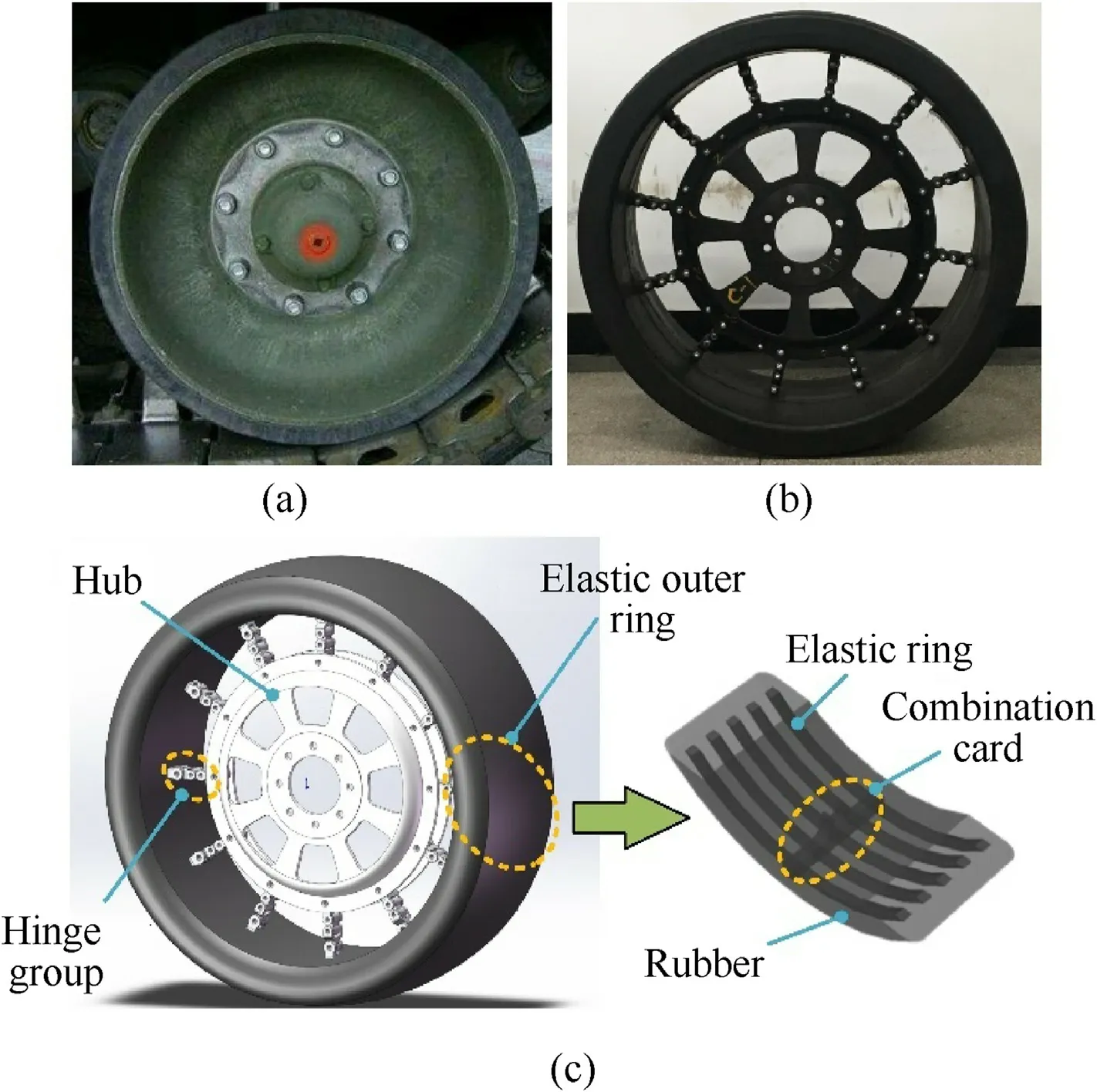
Fig.1. Structure: (a) Rigid road wheel; (b) Flexible road wheel; (c) Structure diagram of flexible road wheel.

Fig. 2. Load-bearing modes: (a) Rigid road wheel; (b) Flexible road wheel.
Due to the unique structure of the flexible road wheel,its loadbearing and contact characteristics are different from the traditional rigid road wheel,as shown in Fig.2.Fig.2(a)shows the loadbearing mode of the rigid road wheel, which is usually called the bottom load which occurs in rigid wheels or solid tires.As shown in the Figure,only the part of the road wheel in contact with the track bears the load, and the loading efficiency is extremely low. In addition, the rubber is subjected to two-directional compression from the rigid crawler belt and rim,and the deformation amount is large which is easy to heat up, causing overheat and damage of rubber.
Fig.2(b)shows the unique suspension load-bearing mode of the flexible road wheel.When the wheel is loaded,the hinge group of the non-contact area is in tension, and the elastic outer ring is subjected to the elliptical deformation caused by the tension from the hinge groups.The hinge group in the contact area is will be free to bend without force. This suspending load-bearing structure is more evenly stressed, and the bearing capacity per unit mass is higher. Besides, the rubber at the bottom of the road wheel only bears one-directional extrusion from the crawler belt, allowing greater deformation in the radial direction, thus reducing the contact pressure between the wheel and crawler belt which is benefit to improve the motility and trafficability of tracked vehicles.
During the operation of the vehicle, the friction between the crawler belt and road wheel will drive the elastic outer ring to rotate and pull the hub through the hinge groups.The hinge group will undergo a cyclic reciprocating process of being pulled, freely bent and then pulled.The hub is suspended in the elastic outer ring at any moment, so the excitation from the road surface will be alleviated by the deformed elastic outer ring and instantaneously randomly bent hinge groups.Therefore,the flexible road wheel has superior vibration damping performance compared to the rigid road wheel.
3. Finite element theory and numerical method of modal analysis
3.1. Finite element solution of dynamical system
According to the basic theory of the dynamic system, the basic equation for solving the dynamic response is:
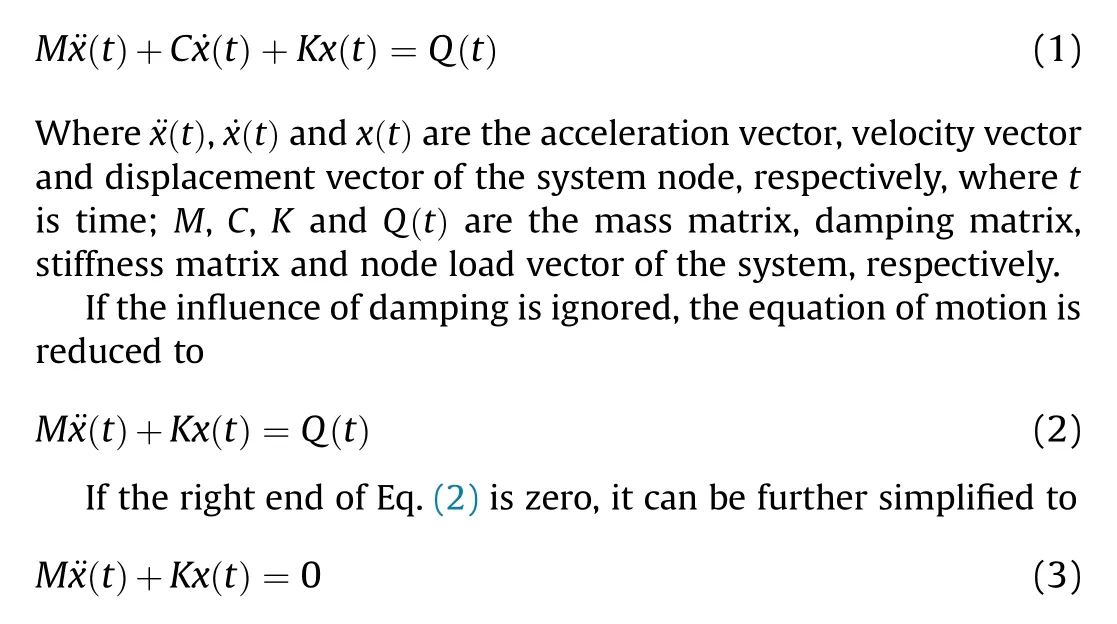
Eq. (3)is the free vibration equation of the system,from which the natural frequency and mode of the system can be solved.
3.2. Natural frequency and modal solution method
Solving the natural frequency and modal problems of the system is actually solving the generalized eigenvalue problem of Eq.(3).In the general finite element analysis, the degree of freedom of the system is very large, and the direct calculation of Eq. (3) is very expensive. When studying the response of the system, it is often necessary to know only a few lower eigenvalues and corresponding eigenvectors.Therefore,in the finite element analysis,some solving methods that can meet the accuracy requirements and improve the computational efficiency are developed. From mainstream numerical methods used commonly in engineering design can be outlined GDQM (generalized differential quadrature method)[30,31]. These methods directly solve the eigenvalue problems of differential equations numerically,and have the advantages of high accuracy and adaptability. From newer methods can be outlined HOHWM (higher order Haar wavelet method) [32-34]. These higher order methods have been utilized with success for free vibration analysis and allow to reduce computational cost substantially.In the finite element analysis software ABAQUS,four solution method include matrix inverse iterative method,subspace iterative method, Ritz and Lanczos vector direct superposition method are provided. The matrix inverse iterative algorithm is simple and suitable for solving a small number of eigenvalues,but the subspace iterative method is to apply the inverse iterative method to the case of using several vectors to iterate simultaneously, that is, to solve more eigenvalues.The common feature of Ritz and Lanczos vector direct superposition method is to directly generate a set of Ritz or Lanczos vectors, reduce the motion equation, and then solve the eigenvalue problem of the reduced motion equation to obtain the characteristics of the original system. This solution avoids the iterative steps of the inverse and subspace iterative method,which has a higher computational efficiency.In this study,Lanczos vector direct superposition method is used to solve the free vibration equation of flexible road wheel.
4. Finite element modelling of rigid and flexible road wheel
4.1. 3-D geometrical model and mesh generation
The flexible road wheel is assembled from individual parts,and the movement of the wheel is realized by the interaction between the each parts. Therefore, multiple coupling factors include the structure of the parts, the connection and assembly relationship between the parts, and the force transmission make the establishment of finite element model of the flexible road wheel very complicated. To improve the efficiency of modelling and solution,the structure of flexible road wheel is reasonably simplified without affecting the function of each components. The complex hinge group is simplified to a 3-link structure. The elastic ring wound with steel wire is simplified into a ring with a rectangular cross section.The load is assumed to be applied at the centre of the road wheel. The relative slip and contact between the elastic ring and rubber is ignored,and they are considered to be a whole.
The structure of the rigid road wheel is relatively simple, in which the rim,spoke and hub are integrated into one piece,and the rim is covered with a layer of rubber. The components of the flexible road wheel,such as the hub,hinge group,rubber layer,and the wheel disc of the rigid load wheel are all meshed by the solid element C3D8R. The elastic ring embedded in the rubber layer is modelled by the beam unit B31.All components of the flexible and rigid road wheel are built in the 3D modelling software CATIA and then imported into ABAQUS for assembly.Finally,the established 3-D finite element models of the rigid and flexible road wheel contain 142865 and 267865 elements, respectively, as shown in Fig. 3.
4.2. Definition of material parameters
The definition of material properties is an important part of finite element modeling of flexible road wheels, which directly affects the accuracy of simulation results. The material of the flexible road wheel is mainly composed of rubber and various metal materials. Among them, the properties of rubber materials are obtained through test methods and literature. The properties of metal materials are obtained through related literature or provided by suppliers, including: Young's modulus, Poisson's ratio and density are shown in Table 1.
Rubber is an almost incompressible superelastic material with complex mechanical behaviour. The deformation process is accompanied by large displacement and large strain, and it has double nonlinear characteristics of geometry and material [35,36].The Mooney-Rivlin model[37,38],which have been widely used in engineering, can basically satisfy the mechanical performance simulation of the rubber materials,and the typical binomial thirdorder expansion of its constitutive model can be expressed as:

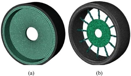
Fig. 3. 3-D finite element model: (a) Rigid road wheel; (b) Flexible road wheel.
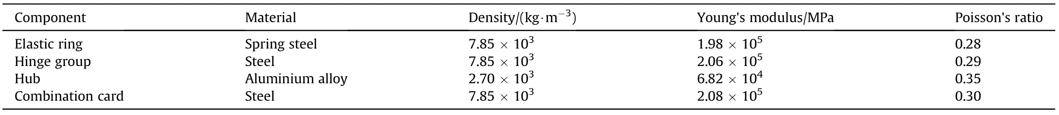
Table 1 Material properties of flexible road wheel.
The stress-strain relationship of the material constitutive model is defined as:Mooney-Rivlin constitutive model. A total of 3 sets of tests were performed,and the 3 sets of data were averaged to obtain the fitting results of the model parameters as shown in Table 2.
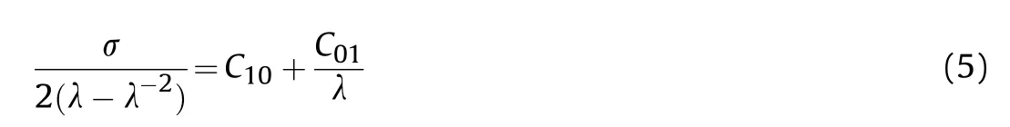
The rubber material coefficients Cand Cin Mooney-Rivlin model can be determined by fitting the axial tensile test data. σ and λ respectively indicate the stress and strain of the rubber material in the stretching process.
The rubber material tensile experiment is carried out on the tensile testing machine. The test pieces included tread rubber and flexible carcass, 3 pieces were prepared for each. The size of the rubber dumbbell-shaped specimen prepared according to the national standard is shown in Fig.4,and the thickness of the specimen is 2 mm.
In the process of testing, fix the sample within the effective range of the test. In order to ensure the accuracy of the measurement, the measurement position is far away from the clamping part. The loading speed of the tensile testing machine is set to 450 mm/min, and the test environment temperature is controlled at 23C ± 2C, the test process is shown in Fig. 5.
The test data measured by the rubber specimen was identified according to formula (6) to obtain the two parameters of the

Fig. 4. Structure diagram of the test rubber specimen.
4.3. Interaction, boundary and loading conditions

Fig. 5. Tensile test of rubber material.

Table 2 Mooney-Rivlin model parameter fitting results.
When the assembly of the flexible or rigid road wheel is completed, it is necessary to define the interaction relationship between the assemblies,the boundary and loading conditions.The friction between all parts is ignored by setting the self-contact to be frictionless. The rotary effect between the hinge and hub or two hinges is simulated by connecting two reference points coupled to the inner surface of the pin bore using “hinge connector”. The elastic ring is embedded in rubber layer by“embedded element”.A reference point coupled to the inner surface of the hub is set at the centre of the hub, and are used to control the translational and rotational degree.
5. Experimental study of modal characteristics
The experimental modal analysis technology has also been widely used to study the tyre vibration characteristics.In this study,the hammering method is used to study the modal characteristics of the flexible road wheel, and the natural frequency and mode shape of the flexible road wheel are obtained.
The general analysis system of modal test includes an excitation system, a signal measurement acquisition system, and an analysis system.The specific process of obtaining the modal parameters by the test method is as follows: First, the excitation driving input is carried out by striking the test wheel with a force hammer; then,the charge amplifier is used to introduce the data acquisition and processing system;next,the modal identification and verification is performed by the time and frequency domain analysis method;Finally, the natural frequencies, damping ratios and modes of the measured flexible road wheels are obtained.
The main equipment involved in the test includes multi-channel data acquisition systems, acceleration sensor, workstation, etc. as shown in Fig.6(a).Considering the special structure of the flexible road wheel, the radial circumference of the tread of the elastic outer ring is evenly arranged and identifies 12 pick-up points. The modal test and the pick-up position of the road wheel are shown in Fig. 6(b). In the test, the modal experimental analysis system LMS Test. Lab was set to have a frequency bandwidth of 512 Hz and a frequency resolution of 0.83 Hz.
6. Results analysis and discussion
6.1. Modal array analysis
The vibration modes of the road wheels can be divided into three types: radial vibration, lateral vibration and circumferential vibration. Considering that the high frequency vibration has little effect on the whole vehicle,the first six vibration modes of the road wheels are extracted and analysed in this study. Fig. 7 shows the predicted first six vibration mode shapes of the flexible road wheel.It can be found that the vibration deformation of various modes mainly occurs in the elastic outer ring, and the vibration of the hinge groups and hub is relatively small.The first two orders of the mode shape are similar, and the main deformation is the in-plane staggered deformation. With the increase of the order, the mode shape becomes more and more complex. The third mode shape is mainly in-plane bending deformation with three petals shape.The fourth mode shape is mainly in-plane and axial bending coupling deformation, and the in-plane mode is four petals shape. The fifth mode shape is similar to the fourth, but the axial bending deformation is more complex. The sixth mode shape is mainly the coupling deformation of in-plane and axial bending, and the inplane mode shape is in the shape of six lobes.
Fig. 8 shows the predicted first six modal shapes of the rigid road wheel. It can be found that there are some differences between the modal shape of the road wheel and those of the flexible road wheel.It is found that in the first three orders,the deformation of the whole road wheel including tread, rim and hub, is large.However, with the increase in the order of the array, the deformation is mainly concentrated in the tread and rim, and the deformation of the hub is smaller.
Fig.9 shows measured mode shapes of the flexible road wheel.It can be seen that the modal shape of the flexible road wheel becomes more and more complicated with an increase in modal order. The 1st to 6th modal shapes of the elastic outer ring are dislocation, ellipse, three petals, four petals, five petals and six petals, respectively. In addition the test results are basically consistent with the simulated results,which verifies the accuracy of the finite element model.
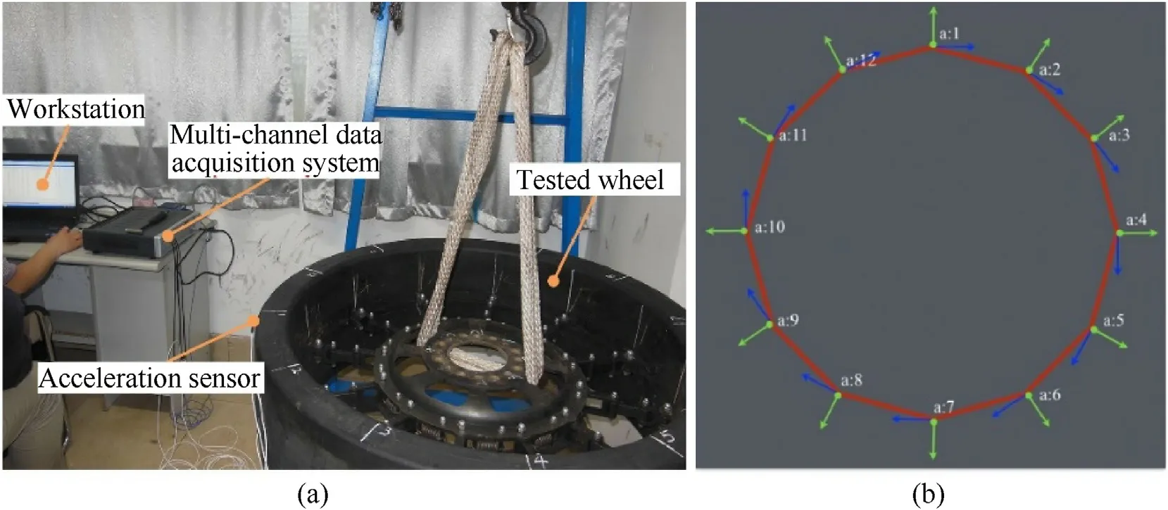
Fig. 6. Modal test of flexible road wheel: (a) Main equipment; (b) Pick-up position.

Fig. 7. Predicted modal shape of flexible road wheel: (a) 1st; (b) 2nd; (c) 3rd; (d) 4th; (e) 5th; (f) 6th.
6.2. Natural frequency analysis
Natural frequencies are the frequencies that are most prone to vibration when structures are disturbed. They can also be called characteristic frequencies or resonance frequencies. The natural frequencies and modes can be obtained by solving the characteristic equation.When the external excitation frequency of the wheel is equal to or approximate to the natural frequency of its structure,resonance will occur.
The correctness of the simulation calculation is verified by the modal characteristic test of the flexible road wheel, and the error between practiced and measured results is analysed.Table 3 shows the comparison of the practiced natural frequency obtained by the finite element model and the measured natural frequency obtained by the modal experiment.It can be seen from Table 3 that the finite element calculation results are different from the experimental measurement results. The difference between experimental and numerical results is caused by complex simulation model and inaccuracies in experimental study performed. The flexible road wheel is a complex composite structure,it is difficult to accurately measure and calculate the basic parameters of the composite material. In real life, it is a quite complicated to achieve exactly free boundary conditions.The applied boundary conditions are not pure free as assumed in the case of free vibrations.
Table 4 shows the predicted natural frequencies of the various stages of the flexible and rigid road wheel in the free vibration state.It can be seen that the natural frequency of the flexible road wheel under each order is lower than that of the rigid road wheel,but as the order increases,the difference between them increases first and then decreases.
6.3. Influence factors analysis
The orthogonal experiment method is to use the orthogonal table method to carry out the experiment, and find out which variable may affect the final result the most.By finding out several representative data to find the best or better scheme, it is a better production condition or mechanical characteristic parameter in practice.Orthogonal test method is a simple,fast and effective test method,which can compare the contribution of different variables to the same objective function. The basic steps of the orthogonal test method mainly include the following:1.Define the purpose of the test and the selection of the test indexes; 2. Select the factors and determine the level; 3. Select the orthogonal table; 4. Define the test scheme and get the test results according to the test scheme; 5. Analyse the results by using the statistical method.
The purpose of this study is to provide a method to evaluate the influence of the structure and material characteristics of the flexible road wheel on the natural frequency,so as to evaluate the potential factors that significantly affect the natural frequency in different parameters. Considering the structural characteristics of the flexible road wheel, seven variables including the cross-sectional area and elastic modulus of the elastic ring, the thickness and elastic modulus of the rubber, the number and elastic modulus of hinge groups and the elastic modulus of the hub are selected, and three levels are determined, as shown in Table 5.

Fig. 8. Predicted modal shape of rigid road wheel: (a) 1st; (b) 2nd; (c) 3rd; (d) 4th; (e) 5th; (f) 6th.
Considering the interaction of variables, 18 experimental schemes are listed in orthogonal table L18(3),as shown in Table 6.Then, according to the test conditions in orthogonal table, the corresponding finite element model of the flexible road wheel is established,and the influence level of the seven factors on the firstorder natural frequency of the flexible road wheel is determined through simulation, which provides some reference for further structural optimization design of the vibration characteristics of the flexible road wheel.
Fig. 10 summarizes the first-order natural frequency of the flexible road wheel with different structural and material parameter levels. It can be seen from Fig.10 that the contribution of the influencing factors to the first-order natural frequency of the flexible road wheel is in order of the number of hinge groups, the elastic modulus of hinge groups, the elastic modulus of hub, the cross-sectional area of elastic ring, the elastic modulus of elastic ring,the thickness of rubber and the elastic modulus of rubber.Only the thickness of the rubber has a negative effect, that is, with the increase of the thickness of the rubber, the natural frequency decreases. The other influencing factors are all have positive effect,that is, with the increase of influencing factors, the natural frequency increases. The number of hinge groups has the greatest influence on the natural frequency, because the increase of hinge groups leads to the increase of mass and the rigidity of the flexible road wheel. Therefore, in the structural design of flexible road wheel,we should focus on the design of the number and material of hinge group to avoid the resonance of the flexible road wheel.
7. Conclusion
In this study,a new combined type of flexible road wheel which has high load-bearing efficiency, good cushioning and vibration reduction performance was proposed. Through a combination of numerical simulation and experiment, the vibration modal characteristics of the flexible road wheel and its influencing factors have been studied in depth.A detailed three-dimensional finite element model of the flexible road wheel was established by using the finite element analysis software ABAQUS. The accuracy of the finite element model was verified by modal tests.The verification results show that the three-dimensional finite element model of the flexible road wheel is accurate and reliable. It can accurately simulate the modal vibration characteristics of the road wheel,and the calculation process is relatively simple and rapid, which is an ideal tool for studying the vibration characteristics of the road wheel.
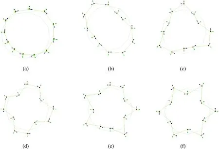
Fig. 9. Experimental modal shape of flexible road wheel.
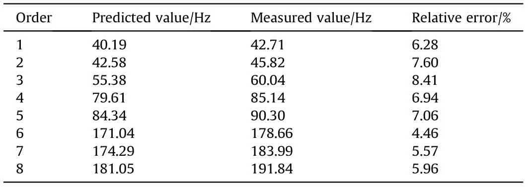
Table 3 Comparison of the predicted and measured natural frequencies of flexible road wheel.
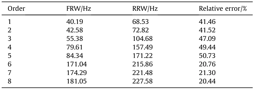
Table 4 Comparison of the predicted natural frequencies of flexible and rigid road wheel.
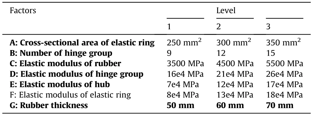
Table 5 Design parameters of flexible road wheel for sensitivity study.
On this basis,the modal vibration characteristics of the flexible road wheels were studied, and compared with those of the rigid road wheels. The simulation results show that the natural frequency of the flexible road wheel is always lower than that of the rigid road wheel, and the difference increases firstly and then decreases with an increase in frequency. The vibration modes of the flexible road wheel are mainly presented in the form of in-plane and axial bending vibration at the elastic outer ring. However, the vibration modes of rigid wheels are mainly presented in the form of axial bending and in-plane torsional vibration at the rim and rubber parts.
Besides, the effects of various factors on the modal characteristics of the flexible road wheels are also analysed using the methodof orthogonal experimental design. The number of hinge groups has the greatest impact on the natural frequency, because the increase of hinge groups leads to the increase of the weight and stiffness of the road wheel. In the structural design, the structure and material properties of the hinge groups should be considered.
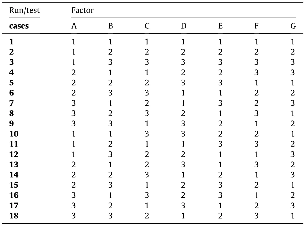
Table 6 Orthogonal array for vibration modal simulation.
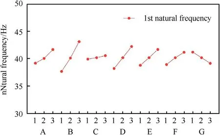
Fig.10. Influence of different factors on natural frequency of flexible road wheel.
The research results reveal the relationship between the vibration modal characteristics of the flexible road wheel and the structure and material characteristics, and provide a theoretical basis for solving the noise, vibration and comfort problems encountered in the process of matching the tracked vehicle with flexible road wheels.
The authors declare that they have no known competing financial interests or personal relationships that could have appeared to influence the work reported in this paper.
The authors give sincere thanks to the editors and the reviewers for their patient work and constructive suggestions.This work was supported by the National Natural Science Foundation of China[grant numbers 11672127,51605215],the Advance Research Special Technology Project of Army Equipment[grant number AGA19001],the Army Research and Technology Project [grant number AQA19001], the Innovation Fund Project of China Aerospace 1st Academy [grant number CHC20001], the Special funded project of China Postdoctoral Science Foundation [grant number 2019T120450]and the Fundamental Research Funds for the Central Universities [grant number NP2020407].
杂志排行

Defence Technology的其它文章
- Influence of carbide ceramic reinforcements in improving tribological properties of A333 graded hybrid composites
- Effects of particle size and content of RDX on burning stability of RDXbased propellants
- Analysis of temporal and spatial distribution characteristics of ammonium chloride smoke particles in confined spaces
- Experimental investigations on small-and full-scale ship models with polyurea coatings subjected to underwater explosion
- Numerical simulation of radiated noise during combustion of energetic materials in a closed bomb
- Topology optimization of reactive material structures for penetrative projectiles