Experimental investigations on small-and full-scale ship models with polyurea coatings subjected to underwater explosion
2022-07-27JianLiuFengjiangAnChengWuShashaLiaoMingxueZhouDongyuXueHuanGuo
Jian Liu,Feng-jiang An,Cheng Wu,Sha-sha Liao,Ming-xue Zhou,Dong-yu Xue,Huan Guo
State Key Laboratory Explosion Science and Technology, Beijing Institute of Technology, Beijing,100081, China
Keywords:Polyurea coatings Small-scale model Full-scale ship Underwater explosion Blast resistance
ABSTRACT Nowadays, the mitigation of damage to a ship caused by the underwater explosion attracts more and more attention from the modern ship designers.In this study,two kinds of scale tests were conducted to investigate the effects of polyurea coatings on the blast resistance of hulls subjected to underwater explosion. Firstly, small-scale model tests with different polyurea coatings were carried out. Results indicate that polyurea has a better blast resistance performance when coated on the front face,which can effectively reduce the maximum deflection of the steel plate by more than 20% and reduce the deformation energy by 35.7%-45.4%. Next, a full-scale ship (approximately 50 m × 9 m) under loadings produced by the detonation of 33 kg of spherical TNT charges was tested, where a part of the ship was coated with polyurea on the front face (8 mm + 24 mm) and not on the contrast area. Damage characteristics on the bottom were statistically analyzed based on a 3D scanning technology, indicating that polyurea contributes to enhancing the blast protection of the ship. However, damage results of this test were different from those of the small-scale tests. Moreover, the deformation area of the bottom with polyurea was greatly increased by 40.1%to disperse explosion energy,a conclusion that cannot be drown from the small-scale tests.© 2021 China Ordnance Society. Publishing services by Elsevier B.V. on behalf of KeAi Communications Co. Ltd. This is an open access article under the CC BY-NC-ND license (http://creativecommons.org/licenses/by-nc-nd/4.0/).
1. Introduction
The survivability of ships under high intensity impulsive loadings, including in blast events, is an important factor in designing and constructing naval ships [1]. Many efforts have been made to improve the blast resistance of ship structures so as to mitigate the devastating effects of underwater explosions. Chen et al. [2]experimentally investigated the dynamic response of a scale ship model using rubber sandwich with the square honeycomb core coatings subjected to underwater explosion. Keon [3] studied the effects of surface coatings on metal cylinders in an underwater explosive environment.Cichocki[4]also presented some results of a study concerning the protective capacity of containment structures subjected to underwater explosion of spherical charges.More detailed research by Brasek [5] on the one-dimensional system demonstratd that the threshold value may be very depending upon the geometry and material properties of both the coating and the structure.
It is also clear from the literatures that the choice of the coating material is of particular importance. In the past several decades,coating steel plates with polyurea layers has been the focus of many studies [6,7]. And polyurea has been proven to improve the blast resistance of steel members during underwater explosion events[8,9]. Polyurea is an inexpensive, fire-resistant, synthetic, highstrength/high-elongation coating that is typically spray cast onto ship hulls to promote their performance when subjected to underwater explosion. In addition, since the density of the polyurea coating is close to that of water,polyurea was found to be capable of increasing the total blast resistance of the ship structure without significantly increasing the surface density [10,11].
In this regard, experimental, theoretical and numerical investigations have been carried out to understand the mechanisms whereby polyurea coatings minimize damage[12-22].Amini et al.[6][[,7]discussed the effect of the location of polyurea coatings on circular steel plates and found that the polyurea applied to the loading surface the of steel plates could not improve the performance of the plates,but rather promoted their failure.It was found that the polyurea coatings de-bonded over a circular area,resulting in a hyperelastic extension of the polyurea and a maximum transient deformation approximately twice that of the bare steel plates.Kathryn Ackland [12] conducted experimental and numerical studies to investigate the effect of polyurea coatings on the blast resistance of mild steel plates. Gardner N et al. [13] indicated that applying polyurea behind the foam core and in front of the back face-sheet will reduce the back face deflection, particle velocity,and in-plane strain. Bogoslovov et al.and Roland et al. [17] performed impact experiments on polyurea-coated steel plates to study the effect of impact-induced glass transition mechanism of polyurea on impact/shock energy absorption.Damith Mohotti[18]evaluated the effectiveness of polymer coatings in reducing blastinduced deformation of steel plates. Moreover, purely numerical investigations have been carried out and indicated that back face coating of polyurea on steel plates can reduce the potential deflection of the plates [19]. He, Zhenhong, et al. found that the deformation magnitude was monotonically decreased by either increasing or decreasing the standoff distance from the threshold value through numerical and experiment methods [21].
There are many types for studying underwater explosions,such as electric spark tests, small-scale tests and full-scale tests. The electric spark tests are generally to investigate the impact and vibration on the hull caused by bubbles and jets in underwater explosions [23,24]. The small-scale model explosion tests under various standoff distances is to explore the blast resistance mechanism of coatings. At present, many efforts have been devoted to accurately predicting the loadings characteristics of large charges with scaled down experiments [25]. However, the dynamic responses of the warship cannot be completely equivalent by the small-sized model, including the deformation and cracks of hulls,and the damage of equipment [26,27]. The behavior of polyureacoated different metal plates subjected to shock loadings has been investigated in the past twenty years, studies on the responses of polyurea coated the full-scale ship have not been reported yet. Since ship shock trials require a lot of budget, most relevant studies have focused mainly on small-scale models of ships. In addition, experiments on underwater explosion of highyield explosives are difficult to perform. However, the polyureasteel composite structure has obviously different performance under explosion loadings in the small-and full-scale tests. The conclusions drawn from the small-scale tests may not match those from the full-scale tests. It is necessary to evaluate the damage results differences between them.
Therefore,in this study,small-scale model tests were carried out to investigate the blast resistance of polyurea coatings on steel plates.It was found that polyurea coatings can mitigate the damage to the steel plates, which reduced significantly the maximum deflection and deformation energy.Then an underwater explosion experiment for the large barge with a length of 50 m,a width of 9 m and a thickness of 8 mm was conducted,in which part of the barge was sprayed with polyurea coatings with a thickness of 24 mm.Through the 3D scanning technology, the damage results of the polyurea-coated steel plate and the contrast area were statistically measured.Similar to the small-scale test results,polyurea coatings can also reduce the maximum deflection and deformation energy of bottom in the full-scale ship. However, there are some differences of the results between the small and full-scale models,which are evaluated in subsequent sections.
2. Small-scale model
2.1. Underwater explosion experiment

Fig.1. Schematic diagram of shock wave and bubble pulsation processes.
Underwater explosion is a very complex problem for naval surface ships or submarines. As shown in Fig. 1, the charge is converted into gases with high temperatures and pressures when the explosion takes place. The generated gases interact with the surrounding water in two different phases. The first is the shock wave phase, which causes a rapid rise in the fluid velocity and pressure. The second phase is a radial pulsation of the gas sphere.The water in what is usually called the gas bubble, has a large outward velocity and the diameter of the bubble increases rapidly.For the underwater shock wave pressure, Cole [28] proposed a decay model shown as in Eq. (1):
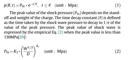
where Kand Aare coefficients that depend on the charge type;Wis the weight of the charge; D is the stand-off distance from the charge at which the pressure is measured. Another parameter of the underwater pressure loading is the time decay constant θ expressed by the following empirical formula:
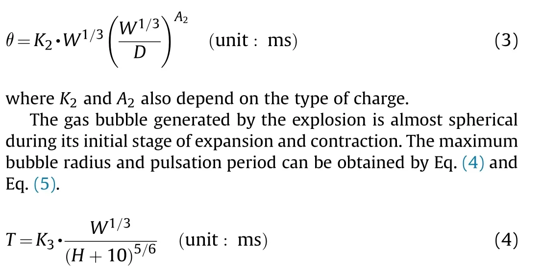

Table 1 Constants of the charge in Eq.(2), Eq.(3),Eq. (4) and Eq. (5).

where, Tis the pulsation period and Ris the maximum bubble radius; H is the explosion depth in meters; Kand Kare also the coefficients related to charges. These constants are shown in Table 1.
Though the peak value of the secondary pressure caused by gas bubble does not exceed 10%-20%of that of the shock wave,action time of which greatly exceeds that of the shock wave.As is shown in Fig.1, the bubble radius increases to its maximum value, then decreases to a minimum value. As the bubble radius decreases, the pressure inside the bubble increases quickly. After reaching its minimum radius,the bubble rebounds because the pressure inside the bubble is very large. There is a slow vertical rise of the bubble after the bubble reaches its maximum radius, followed by an increasingly rapid upward movement as it approaches its minimum radius [28]. Besides, the movement and loadings characteristics of the bubble near the boundary are mainly affected by influence on value of D/R(D is standoff distance andRis the maximum bubble radius) [30,31]. In this study (see Table 2), the standoff distances of the two kinds of scaled tests are less than the maximum bubble radius. A small quality of charge is required to hole a single-hulled vessel during contact explosion,so shock wave plays a more important role than gas bubble.The standoff distance in full-scaled tests is large enough, the effects of both shock wave and gas bubble should be considered at the same time.
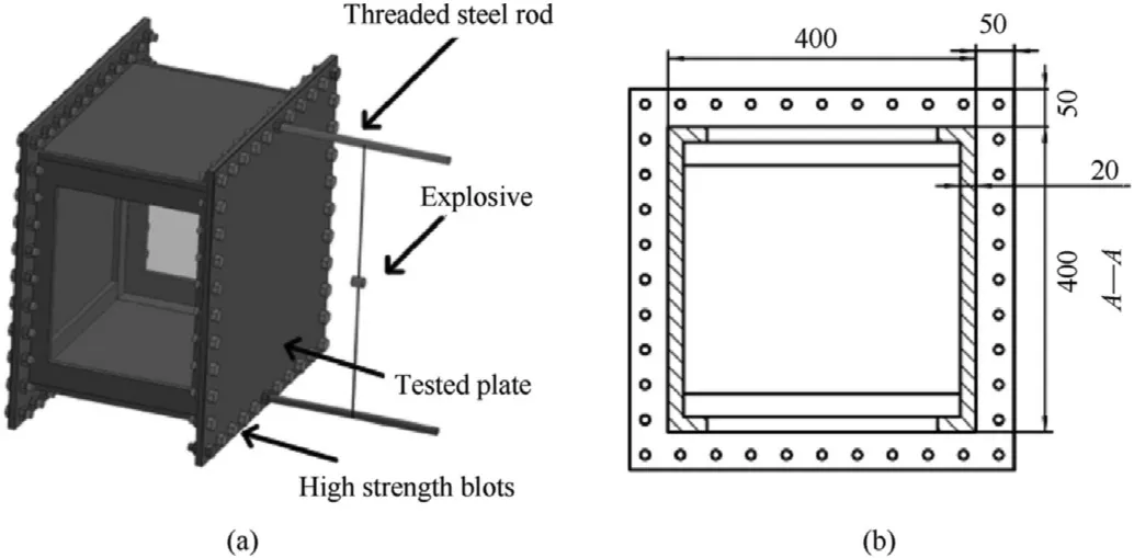
Fig. 2. Small-scale model, (a) The model diagram of the target scale model; (b) The size of the test steel plate.
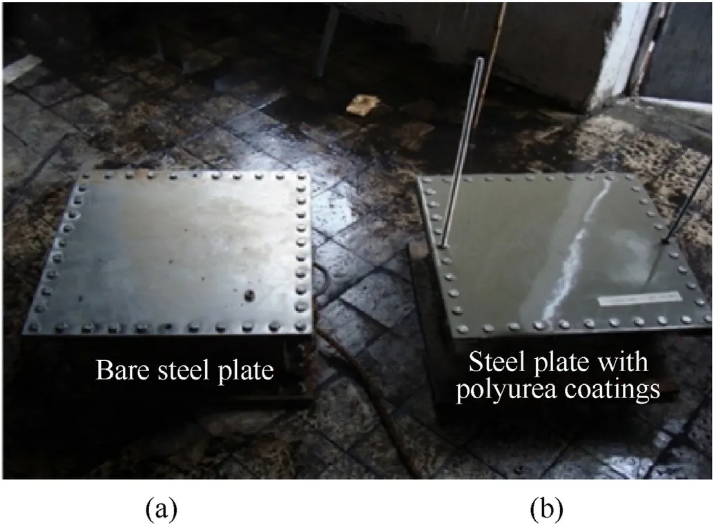
Fig. 3. Test plates, (a)The bare steel plate; (b) The test plate coated with polyurea.
2.2. Setup
As shown in Figs.2 and 3,the small-scale model was composed of a test plate and an air-backed steel box. The test steel plate was fixed on the air-backed box by bolts with a size of 500 mm×500 mm×2 mm.In order to ensure the water tightness,a sealing rubber gasket with a thickness of 1 mm was installed between the test steel plate and the box.The explosive was fixed by two long threaded steel rods, and the distance between the explosive and the test steel plate could be adjusted by the threaded steel rods.
As is shown in Table 3, pure polyurea coatings having good physical properties is very suitable for applications in extreme conditions. Polyurea is a two-component elastomer spray coating material, whose raw materials include isocyanate as component A and resin as component B.The main constituent of resin is diamine oligomer. And no dilution is required.
The cylindrical charge was TNT with a weight of 13 g, which is fixed by two long threaded steel rods,and the standoff distance is adjusted by the threaded steel bars was shown in Fig. 4.
The tests were carried out in a water pool as shown in Fig.5.The length and width of the pool was 2 m×2 m,and the water depth was 2 m.The test setup was hung in the center of the pool and the charge was 0.7 m below the free water surface.
In order to investigate the blast resistance effects of polyurea coatings positions and thicknesses on the test plates, different polyurea coatings conditions and standoff distances were designed for blast tests as shown in Table 4.
2.3. Results and analysis
The damage results of the bare steel plates at different standoff distances are presented in Table 5. As the standoff became larger,less energy generated by the charge affected the test plates,and the damage degree decreased. When the standoff distance was zero,the steel plate had a large 6-Pl crack as shown in Fig. 6(a). As presented in Fig.6(b),the plate did not rupture and only had dishing deformation at the standoff of 10 mm.Thus the 8 mm between the charge and the plate was determined as the appropriate standoff distance for the subsequent tests.

Table 2 Shock wave and bubble characteristics of two kinds of scaled tests.
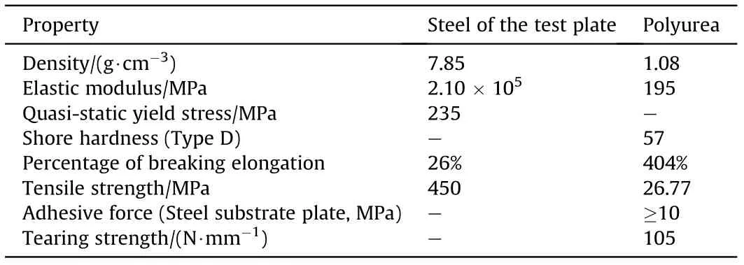
Table 3 Quasi-static properties of steel of the test plate and polyuria.

Table 5 Results of the bare steel plates at different standoff diatances.
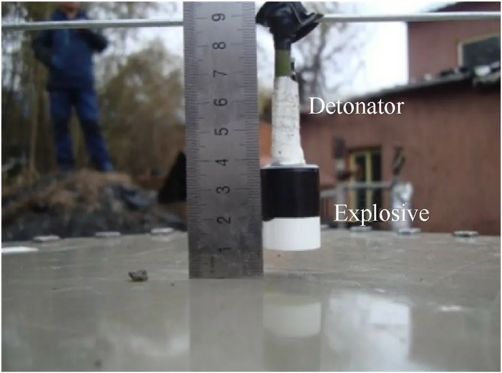
Fig. 4. The cylindrical charge of TNT.
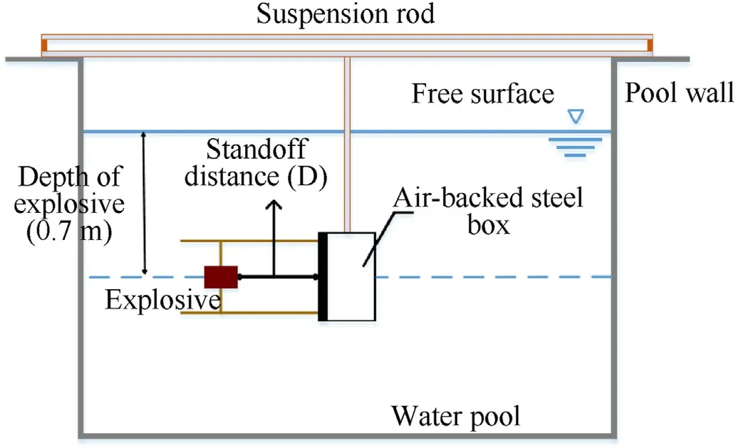
Fig. 5. The equipment schematic of underwater explosion.
Fig.7 shows the damage results of the small-scale models with different coating methods when the standoff distance is 8 mm.The bare steel plate has an obvious 3-Pl crack. However, only a bulge appears on the surface of the steel plate with polyurea. The front face of the polyurea-coated steel plate has a maximum deformation of 70 mm, but that of the back face of the steel plate coated is 80 mm.
As is shown in Fig. 8, the residual deflection of the steel plate sprayed with polyurea on the front surface is smaller than that of the steel plate sprayed with polyurea on the back surface when the plates are subjected to the near-field underwater explosion loadings.
On the one hand, increasing the thickness of the polyurea coatings within a certain range for the two spraying methods can effectively improve the anti-blast performance of the structure.On the other hand, as can be seen from Fig. 9 and Fig.10, unlike the damage to the polyurea coated on the front face of the steel plates,the polyurea that covered the back face of plates not only separated from the substrate plate,but also cracked or even fell off a large area after the blast tests. Particularly, the 4 mm polyurea coating layer completely fell off the substrate and broke up into several small fragments.
The schematic diagram of the fixed air-backed plate subjected to underwater explosion shock wave is shown in Fig.11,where D is the distance between the explosive and the plate, and the generated shock wave velocity propagating along the X axis is V.
According to the Taylor plate theory,the surface pressure of the air-backed plate subjected to the underwater explosion shock wave can be expressed as [32]:

where, pand θ are the peak pressure and time constants of the shock wave,respectively;cis the speed of sound in the water;and ρis the density of water.In Eq.(6),the former pressure represents the pressure obtained by reflection from the rigid wall, and the latter is the influence of the wave generated by the motion of the plate[33].
As shown in Fig.12,the rectangular plate is subjected to loadings p(t) on the surface whose length and width are 2a and 2b,respectively.

Table 4 Test conditions of the small-scale model subjected to underwater explosion.

Fig. 6. Damage results of the bare steel plates at different standoff distances (a) D = 0; (b) D = 10 mm; (c) D = 15 mm.
According to the actual deformation of the rectangular plate under explosion loadings,the final deformation is relatively close to the sinusoidal surface,so the model of the deformation of the plate is expressed as [34]:

where u、v and ware the displacements in x, yand zdirections,respectively;uand vare the maximum displacements in x and y directions,and wis the deflection of the center point of the plate in the z direction.
In the case of plane stress, the strain component of the rectangular plate along the x and y directions is [34]:

where εand εare the strain components in the xand ydirections,respectively; and γis the angular strain.
According to the final deformation of the rectangular plate, it can be known that the final plastic deformation energy of the rectangular plate is mainly composed of three parts, namely, the boundary plastic bending deformation energy (U), the plastic hinge bending deformation energy in the rectangular plate deformation area (U) and the elongation plastic deformation energy due to the membrane stress(U).
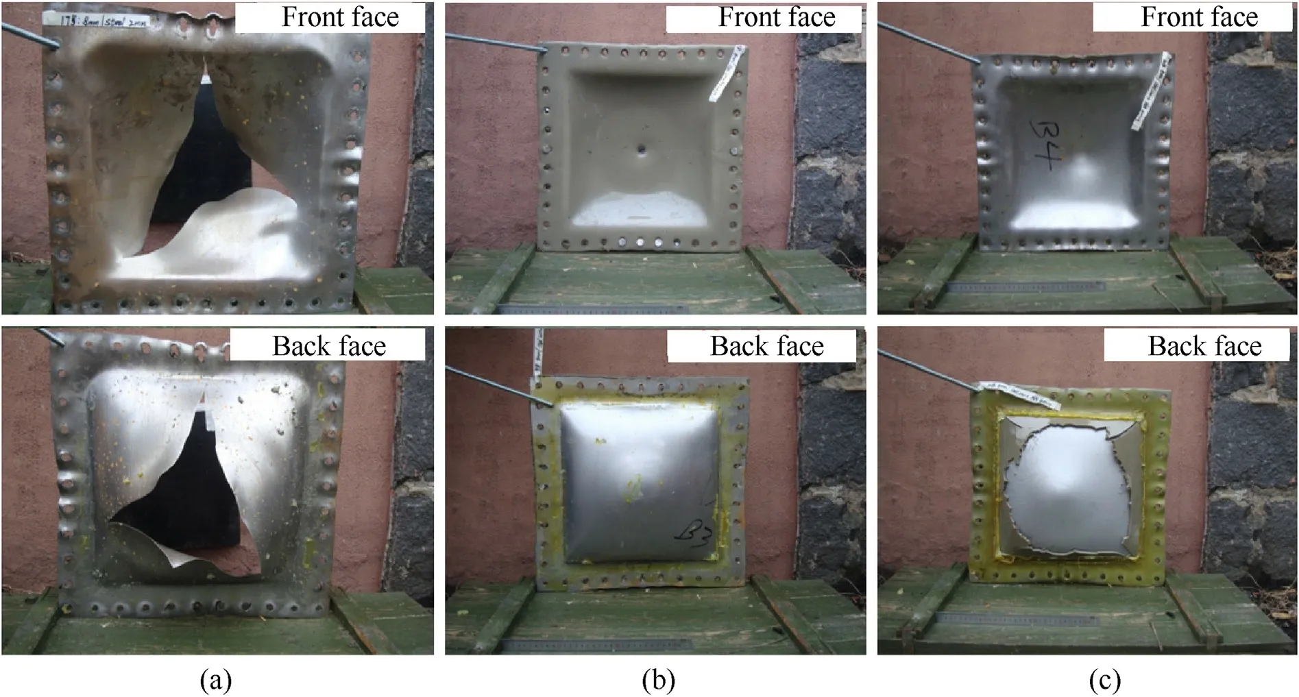
Fig.7. Damages of the three kinds of spraying methods(D=8 mm),(a)The bare steel plate;(b)Polyurea(4 mm)coated on the front face;(c)Polyurea(4 mm)coated on the back face.
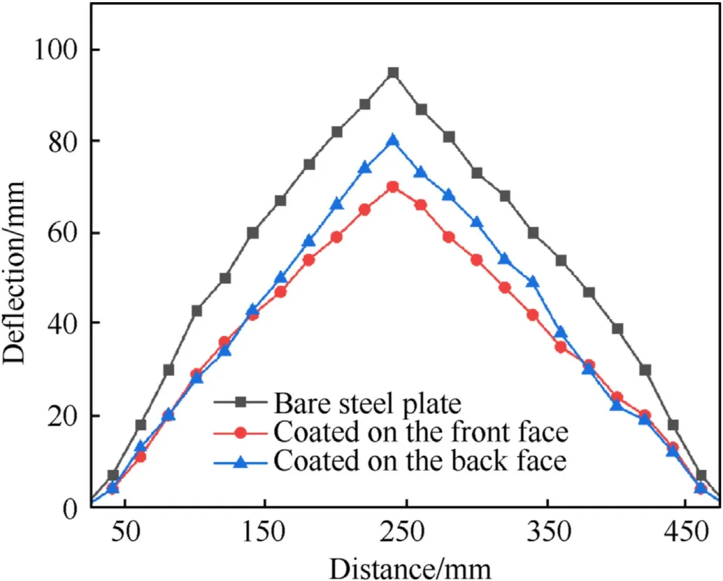
Fig. 8. Deformation profiles of the steel plates (D = 8 mm).
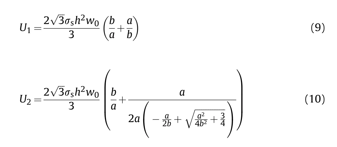
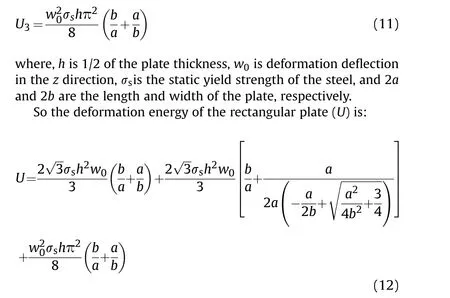
In this small-scale model,a=0.25mb=0.25mh=1mm,andσ=235MPa. Therefore, the deformation energy of steel plates with different polyurea coatings calculated by Eq. (12) are summarized in Table 6.In summary,a part of the underwater explosion energy is reflected back to water by the polyurea coatings, and another part of the energy is dissipated through elastic deformation.
Underwater near-field explosion tests were carried out on the small-scale models, and the following conclusions were initially obtained under different conditions. The integrated substrate plates of the small-scale model were deformed when subjected to underwater explosion, as presented in Fig. 8. Polyurea coated on the both surfaces of the steel plate can enhance the ability of the structure to resist deformation.However,blast resistance effects of polyurea coated on the front face of the plate are better than those of polyurea coated on the back face,as presented in Table 6 which reduces the deflection of the steel plate by more than 20% and reduce the deformation energy by 35.7%-45.4% (2 mm + 4 mm).Besides, increasing thickness of polyurea coatings can effectively improve the anti-blast performance.
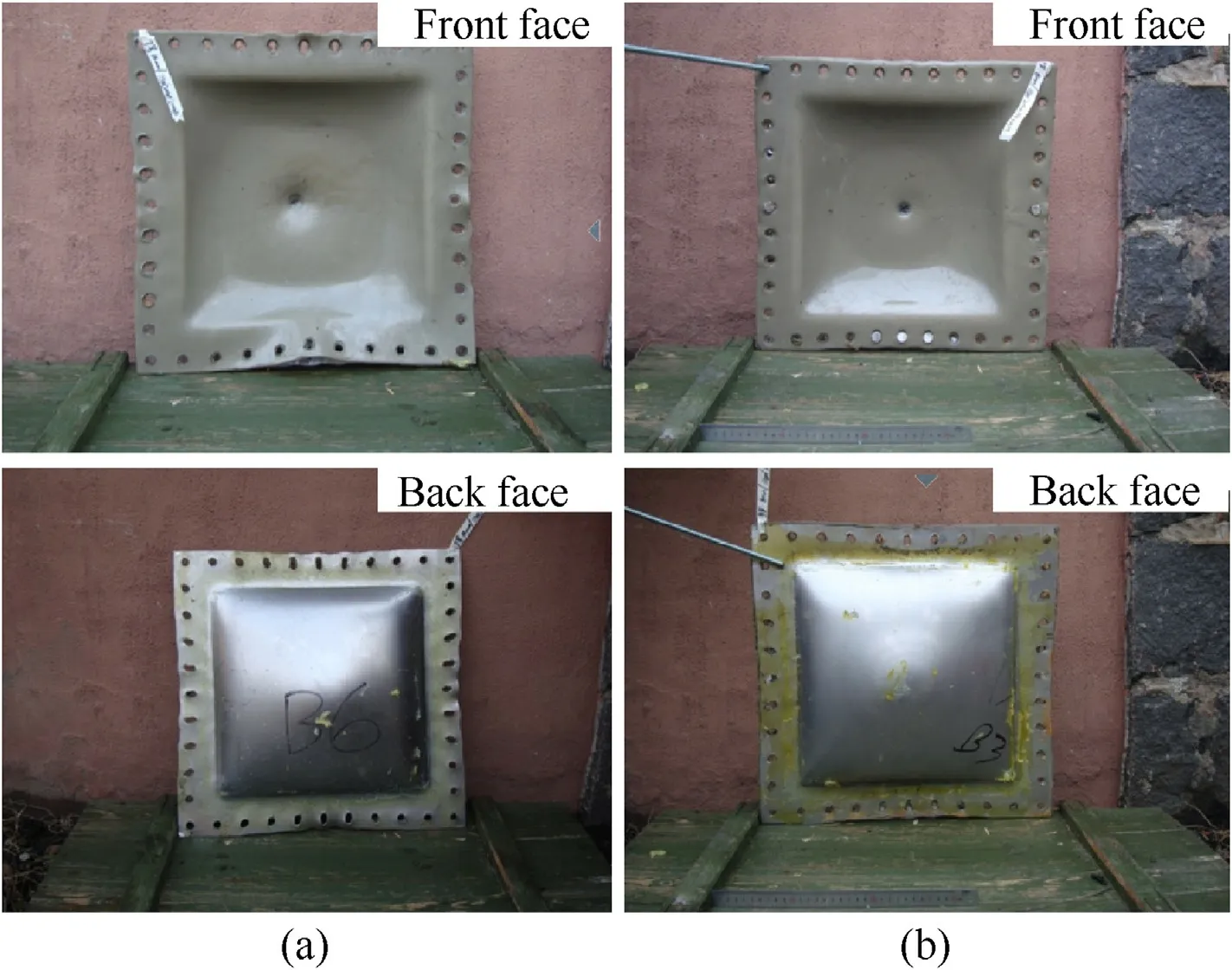
Fig. 9. Damage results of the steel plates with polyurea coated on the front face with different thickness (D = 8 mm), (a) 2 mm; (b) 4 mm.
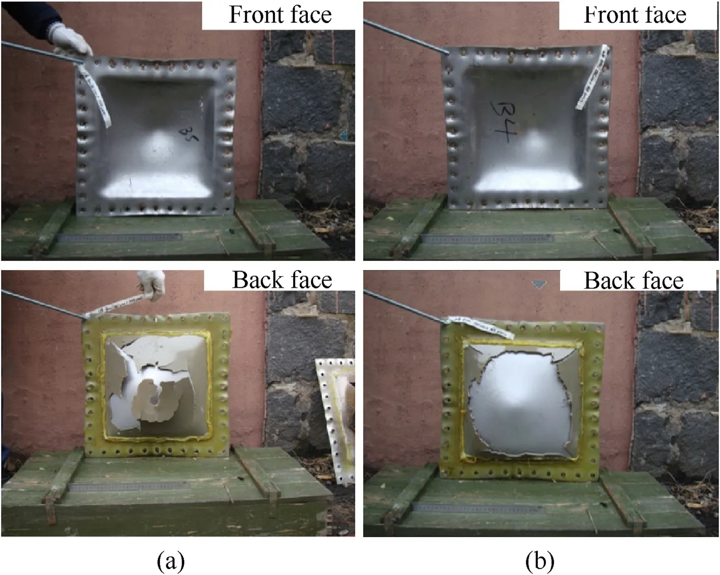
Fig.10. Damage results of the steel plates with different polyurea coated on the back face (D = 8 mm), (a) 2 mm; (b) 4 mm.
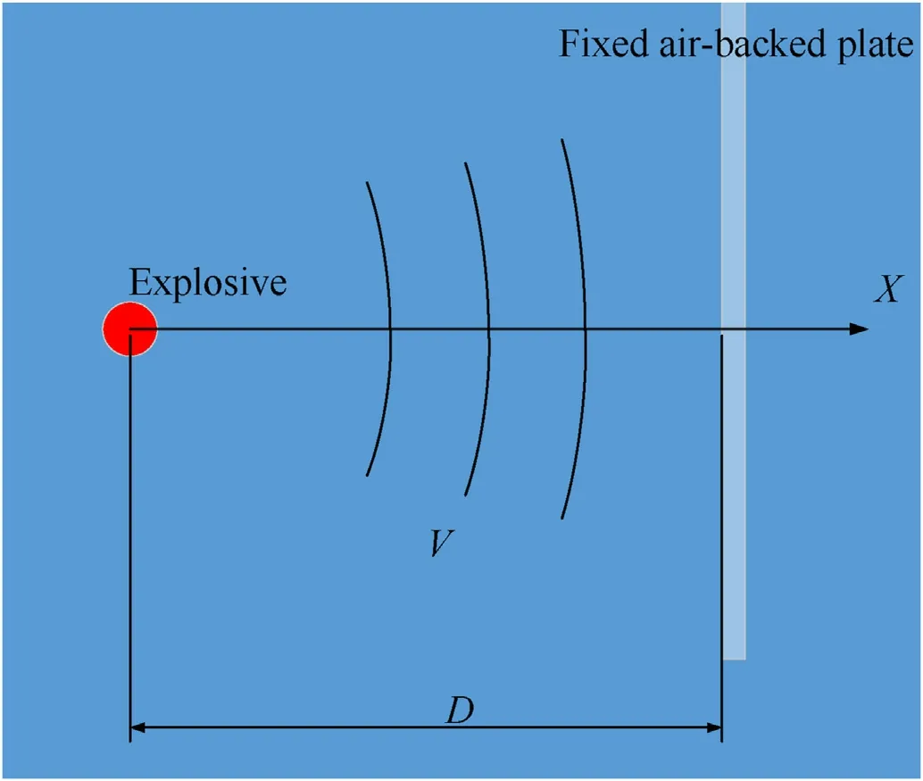
Fig. 11. Schematic diagram of the fixed air-backed plate subjected to underwater explosion.
3. Full-scale ship
3.1. Test ship and polyurea spraying procedure
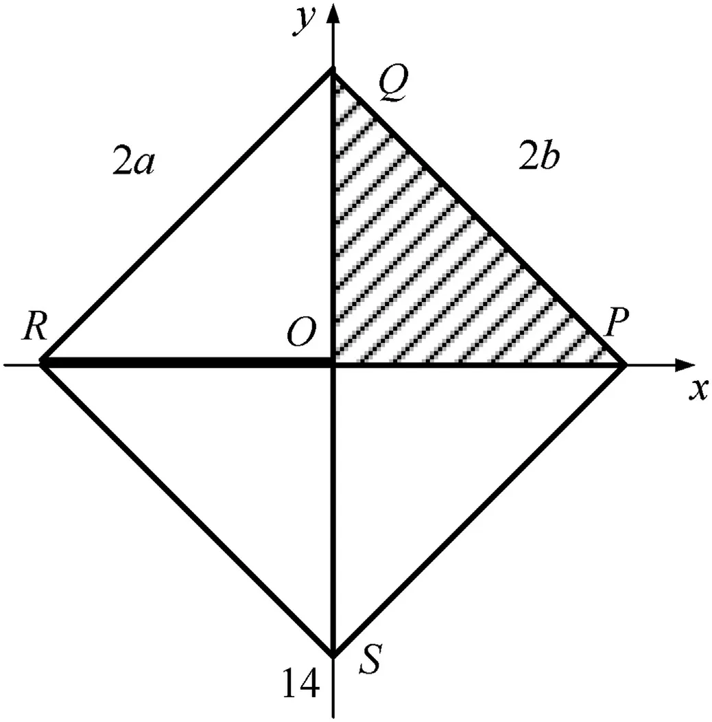
Fig.12. Fixed rectangular air-backed plate.
In this test,polyurea was sprayed on a part of the bottom area of the full-scale ship with a length of 50 m and a width of 9 m in order to investigate the blast resistance effects on the ship subjected to underwater explosion. And the quasi-static properties of steel is shown in Table 7. As shown in Fig.13, the test ship is a steel deck barge with a single bottom and deck. The section of test ship is 50.0 m in total length,9.28 m in width and 8 mm in thickness.Andthe moulded depth and design draft of the ship are 2.48 m and 1.30 m, respectively.

Table 6 Results of blast resistance of different polyurea coatings.

Table 7 Quasi-static properties of steel of the test ship.
The bottom of the ship has a rib every 0.5 m in the transverse direction, and a longitudinal beam traverses through the spraying area and the contrast area in the longitudinal direction. Therefore,the structure of the polyurea spray area and the contrast area at the bottom are the same. What is important is that a transverse bulkhead is arranged between the two areas in order to avoid the coupling effect on the dynamic responses of them.
The spraying process of polyurea coatings is shown in Fig. 14.The installation area is enclosed to meet the temperature and humidity requirements during spraying. Since the steel plate on the bottom is prone to rust due to high humidity,the primer should be applied within 2 h after sandblasting.Moreover,a small amount of spray should be applied to the joints first, otherwise it is easy to cause local uplift.
The polyurea was applied to the outer surface of the bottom form the rib of the No. 51 to No. 43. The spraying area was 4.0 m×8.0 m with a thickness of 24 mm.The schematic diagram of the test ship coated with polyurea coatings is as follows in Fig.15:
3.2. Setup
As shown in Fig.16,the test ship floats on the surface of the sea.The standoff distance(D)between the explosive and the bottom of the ship was 3 m. And the charge was TNT with a mass of 33 kg suspended directly under No. 51 rib, with a horizontal distance of 0.5 m from the polyurea coatings. Due to the ocean current in the test sea, the explosive ball would shift toward the ocean current.According to the calculated results,the explosion center was offset by 0.3 m to the spraying area.
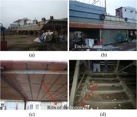
Fig.13. The test ship, (a) The outward; (b) The left port side of the ship; (c) The bottom; (d) The internal structure.
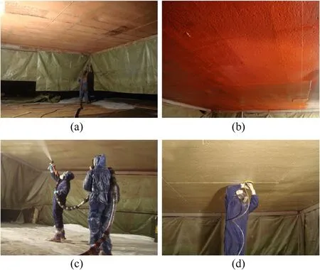
Fig.14. Polyurea spray coating process, (a) Sandblasting; (b) Brushing primer; (c) Spraying polyurea; (d) Polishing edges.

Fig.15. Schematic diagram of the test ship coated with polyurea coatings.
In this test,some necessary measures were taken to reduce the weight of the empty ship and increase the buoyancy.The original Fr 54-Fr 88 bundling on the deck of the target ship was removed,and the original warehouse cover and vents sealed.In order to prevent the ship from sinking after blast events,total of eight steel pontoons with a size of 4.0 m×3.0 m×2.0 m were located on both sides of the ship.
3.3. Results and analysis
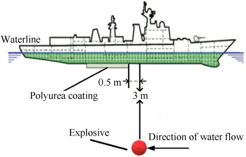
Fig.16. Schematic diagram of experimental set-up.
After the blast events,tested ship was towed ashore,and the test results are recorded and analyzed by a 3D scanner. The 3D laser scanner used for this experiment is Creaform MAXSHOT 3D,which volume accuracy and average error are 0.015 mm/m and 0.005 mm/m, respectively. The principle of 3D scanning technology is laser ranging to measure and record the three-dimensional coordinates,reflectivity and texture information of a large number of dense points on the surface of the target ship at high speed. The threedimensional model of the measured target and data such as lines,surfaces, and volumes are quickly reconstructed through postprocessing software (VXelements). As shown in Fig. 17, the contrast area was severely deformed and broken subjected to the underwater explosion. It can be also clearly seen from the experimental results that there are three cracks in the bare bottom.Two larger cracks appeared on the boundary, and a smaller crack appeared in the center of the bottom.However,the bottom coated with the polyurea was only deformed with no crack.And polyurea had a little peeled off near the edges.
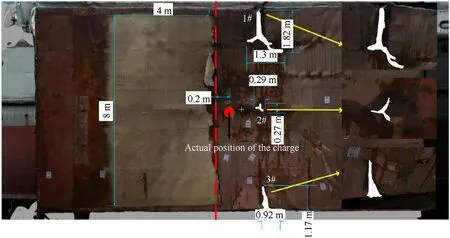
Fig.17. 3D Scanning picture of the damage results of the front face on the bottom.
The center of the plate is prone to be broken because it bears greater loading pressure than other places. The plate in this area moves rapidly causing a large corner at the boundary, which generated cracks easily.
It can be found in Fig.18(a)that the deformation contour lines of the bare steel plate are denser,which means that the deformation is steeper.(During the post-treatment process,the scanning pictures of the polyurea were attached to the back face of the bottom.) In Fig.18(c),the deformation area of the plate with polyurea coatings is greatly bigger than that of the bare steel plate. According to statistics,the deformation area of the plate with polyurea coatings is 24.69 m, but the value for the bare plate is only 17.62 m. The deformation area with polyurea is increased by 40.1%, indicating that the one of the important blast resistance means of polyurea in the full-scale ship is to increase the deformation area to disperse energy.Besides,from Fig.19 it is clear that the maximum deflection of the bare steel plate is 894 mm,while that of the polyurea-coated steel plate is 825 mm.
As shown in Fig.20(a),the back face of the bottom was divided with 7 bisecting lines. The position of Line 4 is close to the longitudinal beam of the bottom of the ship,which has a great influence on the deformation.So the maximum deflection of Line 4 is smaller than those of Line 3 and Line 5 in Fig. 20 (b).
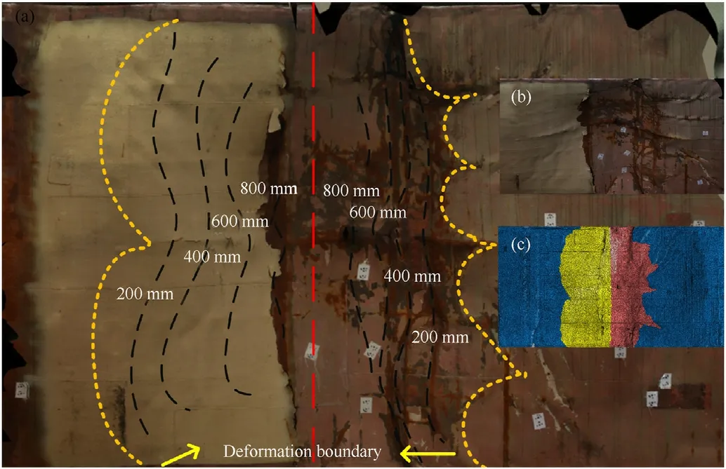
Fig.18. Deformation of the back face of the bottom,(a)Deflection contour lines of the bottom; (b) A partial enlarged view of the deformed position; (c) A comparison of deformation areas.
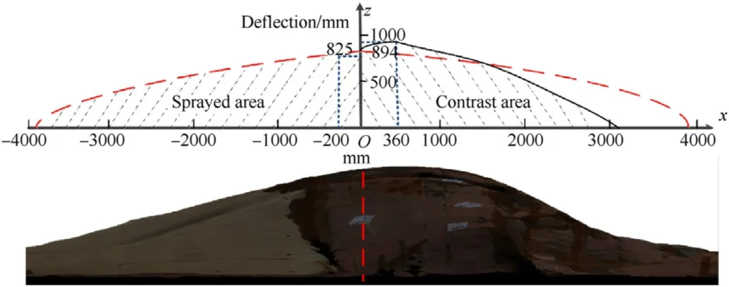
Fig.19. Deformation of the back face of the bottom.
In order to reduce the influence of the longitudinal beam on the analysis of the bottom deformation,Line 3 and Line 5 were placed far away from the longitudinal beam but not close to the boundary.Some points shown in Fig.21 were selected with equal interval,and deflections of these points are summarized in Table 8.
Then,according to Eq.(12),the deformation energy of the steel plate with the polyurea and the bare steel plate are 5.585 MJ and 7.432 MJ, respectively. In this testb= 21.3m, b= 24.5m, a =4.5m,h = 4mmandσ= 315MPa. bis the length of the steel plate with polyurea,and bis the length of the bare steel plate.
The underwater explosion test of the full-scale ship proved the blast resistance of polyurea coatings under the attack of a large equivalent loading. As shown in Fig. 22, the polyurea coatings can maintain the integrity of the bottom without cracks. According to the statistical results, the polyurea coatings can effectively reduce the maximum deflection and the deformation energy of the steel plate by 7.72% and 24.9%, respectively. Last but not least, the deformation area of the bottom with polyurea is increased by 40.1%compared to the contrast area. Larger deformation area can significantly disperse explosion energy and enhance blast resistance, which was not observed in the small-scale model tests.

Fig. 20. The back face of the bottom, (a) 3 D scanning picture of the bottom; (b) The profile diagram of the bottom.
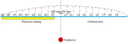
Fig. 21. Points at the same distances from both sides of the explosion center.

Table 8 Deflections of different points at Line 3 and Line 5.
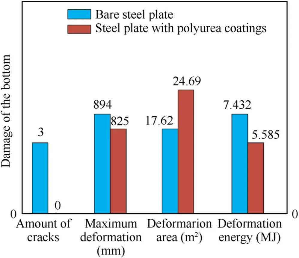
Fig. 22. Comparisons of the damage to the bare steel plate and steel plate with polyurea coatings.
4. Conclusions
This study evaluated the performance of polyurea coated on two kinds of steel plates in the small-and full-scale tests, as shown in Table 9. The key conclusions are summarized as follows.
(1) According to the results of the two kinds of tests, polyurea coatings can obviously improve the blast resistance of ships subjected to underwater explosion loadings. Polyurea coatings dissipate a part of the underwater explosion energy through elastic deformation and reflects another part of the energy back into water due to the mismatch of wave impedance between the steel plate and polyurea. And in generating these effects, the polyurea coated on the front face of the steel plate performs better.(2) In the small-scale tests,results indicated that the damage to the bare steel plate is sensitive to the standoff distance. The reductions of the maximum deflection and deformation energy of the steel plate caused by polyurea coatings(4 mm)on the front face are approximately 26.3% and 45.4%,respectively.Increasing the thickness of polyurea coatings is helpful in reducing the deformation of the testplates. Besides, the polyurea coated on the back face of the plates not only separated from the substrate plate, but also cracked or even fell off a large area after the explosion.(3) In the full-scale ship, the reductions of the maximum deflection and deformation energy of the steel plate are smaller than those in the small-scale model tests. The deformation of the steel plate with polyurea coatings is more gentle and regular compared to the bare steel plate. Moreover, an important conclusion can be drawn from the fullscale ship that polyurea coatings can significantly improve the mechanical properties of the polyurea-steel composite structure. The explosion energy can be dispersed by increasing the deformation area of the bottom with polyurea,which was not observed in small-scale tests. These differences are closely related to polyurea coatings and the model structure, but it is worth evaluating the performance of polyurea coated with different substrates when subjected to various loadings.
5. Future research
Two different scale tests were carried out, which verified the blast resistance effects of polyurea coatings on steel plates subjected to underwater explosion. And differences of the damage mitigation results between small-and full-scale tests were evaluated. However, some important studies need to be continued.
(1) The effects of underwater explosion on a ship are complex,which depend not only on the weight and stand-off distance of the charge, but also on the structure of the ship. A small quality of charge is required to hole a single-hulled vessel during contact explosion. Shock wave plays a moreimportant role than gas bubble. On the contrast, if the standoff distance is large enough, the effects of both shock wave and gas bubble should be considered at the same time.So it is necessary to study the impact of standoff distances on the mechanical behavior and blast resistance effects of polyurea.

Table 9 Comparison of blast resistance results of polyurea coatings in the small-scale models and full-scale ship.
(2) In addition,the relationship between the areal density of the composite structure and blast resistance effects for polyurea coatings with different thicknesses needs to be studied.Moreover, there will be an optimal spraying position and thickness for polyurea coated on a certain steel plate. Numerical simulations should be used to further explore the best polyurea spraying method of for different models.
(3) Polyurea significantly improves the mechanical properties of the composite structure. The mechanical behaviors of polyurea under impact loadings should be studied.At present,we are working on measuring the glass transition,T,of polyurea at pressures up to 6-10 GPa in a diamond anvil cell. In this method, we will obtain some potential parameters of the high strain rate, high pressure dynamics of polyurea to explain the blast resistance mechanism more deeply.
The first author made the contributions to the experimental and writing work, the second author has proposed the idea and innovation points of the present work, and the entire work was supported by the project undertaken by the third author. All of experimental results in this test was recorded by the forth author.The entire work was supervised by the fifth, sixth and seventh author.
The authors declare that they have no known competing financial interests or personal relationships that could have appeared to influence the work reported in this paper.
This paper is supported by the project of State Key Laboratory of Explosion Science and Technology(Beijing Institute of Technology).The project number is NO. QNKT19-04.
杂志排行
Defence Technology的其它文章
- A new model for the expansion tube considering the stress coupling:Theory, experiments and simulations
- Experimental and analytical assessment of the hypervelocity impact damage of GLAss fiber REinforced aluminum
- Effect of the microporous structure of ammonium perchlorate on thermal behaviour and combustion characteristics
- Modeling of bistatic scattering from an underwater non-penetrable target using a Kirchhoff approximation method
- 3,6-bis (2,2,2-trinitroethylnitramino)-1,2,4,5-tetrazine. Structure and energy abilities as a component of solid composite propellants
- Rapid preparation of size-tunable nano-TATB by microfluidics
