Development and validation of a new oxide fuel rod performance analysis code for the liquid metal fast reactor
2022-07-26GuangLiangYangHaiLongLiaoTaoDingHongLiChen
Guang-Liang Yang · Hai-Long Liao · Tao Ding · Hong-Li Chen
Abstract The integrity and reliability of fuel rods under both normal and accidental operating conditions are of great importance for nuclear reactors. In this study, considering various irradiation behaviors, a fuel rod performance analysis code, named KMC-Fueltra, was developed to evaluate the thermal–mechanical performance of oxide fuel rods under both normal and transient conditions in the LMFR. The accuracy and reliability of the KMC-Fueltra were validated by analytical solutions,as well as the results obtained from codes and experiments.The results indicated that KMC-Fueltra can predict the performance of oxide fuel rods under both normal and transient conditions in the LMFR.
Keywords Fuel rod analysis code · Thermal–mechanical performance · Irradiation behaviors · Pellet-cladding mechanical interaction · Liquid metal fast reactor
1 Introduction
Liquid metal fast reactors play an important role in the long-term sustainable development of nuclear energy because of their efficient utilization of uranium resources and reduction in nuclear waste[1],1,1].An assessment of the thermal–mechanical performance of the fuel rod is essential for the safety analysis of fast reactors. Ensuring reliability and integrity under both normal and transient conditions is the main objective [4], 4].
Several studies have been conducted on fuel performance analysis worldwide. Based on the fuel behaviors obtained from experiments, fuel rod performance analysis codes have been developed for different types of reactors,such as COMETHE [6], LIFE [7], and IAMBUS [8].Although the models used in these codes are relatively simplified, they still laid the foundation and main framework of the fuel element performance analysis codes.Because of the slow development of fast reactors, the understanding of the irradiation behavior of fuel elements in the liquid metal fast reactor (LMFR) is insufficient,which leads to the slow development of fuel rod performance analysis codes.In recent years,many countries have promoted research on fast reactors and code development regarding fuel rod performance. Some codes are extended from codes designed for light water reactors, such as TRANSURANUS[9]in Europe and FEMAXI-FBR[10]in Japan.Several original codes have been developed,such as FEAST-OXIDE by Massachusetts Institute of Technology,DEFORM by Argonne National Laboratory,FRED by Paul Scherrer Institut (PSI), and LIFEANLS by China Institute of Atomic Energy. FEAST-OXIDE [11] is an engineering code for evaluating the MOX fuel performance in a sodium fast reactor.DEFORM[12]can calculate the shape change of the oxide fuel pins under transient conditions. FRED[13] is a fuel thermal mechanics code for the transient analysis of fast reactors. LIFEANLS [14] was developed mainly for predicting the fuel performance in the China Experiment Fast Reactor from an engineering perspective.
Each code has its own characteristics and simplifies analysis as much as possible. FRED uses a rigid pellet model,which means that the stress-induced deformation of the fuel pellets is neglected. DEFORM does not provide a detailed analysis of the fission gas release behavior. The fuel rod behavior in LIFEANLS is incomplete,such as not considering cracking-healing and densification of the fuel pellet. Furthermore, the consideration of thermal–mechanical coupling is relatively simple.
In this study,considering the main characteristics of the oxide fuel rod in the LMFR, a code named KMC-Fueltra was developed to evaluate its thermal–mechanical performance. The temperature of the fuel rod was calculated more precisely by considering radial and axial heat conduction. The fission gas release was modeled by a mechanistic theory for both the intra- and intergranular gas behaviors, covering normal and transient conditions. Most of the known phenomena for oxide nuclear fuel in a fast reactor were considered. Subsequently, some validation studies have been carried out to check the accuracy and reliability of this code.
2 Mathematical and physical models
2.1 Thermal analysis
2.1.1 Solid heat conduction
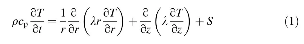
Temperature is important for fuel rod performance analysis because of its influence on material properties,fission gas release, and irradiation behavior. Equation 1 describes the heat conduction in the fuel rod with heat source S, which is solved to obtain the temperature distribution of the fuel pellet and cladding.
2.1.2 Gap heat conduction
The change in gap heat conduction, which depends on the gap width, contact state, gas composition, and plenum pressure,causes a change in the temperature of the fuel rod because of its high thermal resistance.A modified Ross and Stoute model [15] was adopted to calculate the heat conduction (hgap) in the gap under both normal and transient conditions, as shown in Eq. 2. It is composed of three components: gas conduction; solid contact conduction,which is considered when there is contact between fuel pellet and cladding; and radiation between the fuel pellet and cladding surface. Gas conduction, hgas, is related to surface roughness, and the model proposed by Ross and Stoute is adopted [15]. When pellet and cladding mechanical interaction (PCMI) occurs, solid contact
conduction,hsolid,contributes to the gap heat transfer.This part is calculated using the modified Mikic-Todreas model considering the contact pressure and cladding Meyer hardness[16].Radiation heat transfer,hrad,is derived from the general radiation heat transfer equation based on the infinite-cylinder gray-body form [11].

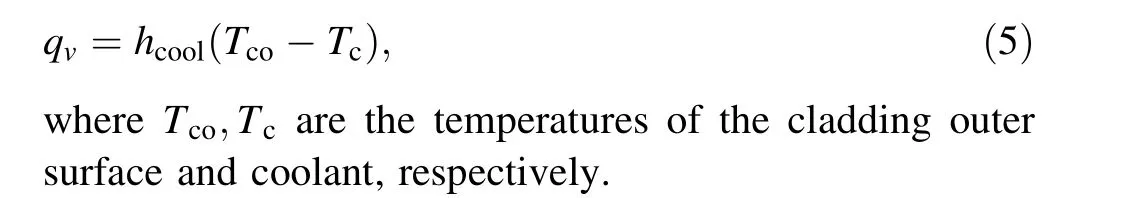
The boundary condition was described by Newton’s law in Eq. 5.Considering that the research object is the fuel rod in LMFR,the heat transfer coefficient,hcool,is calculated by the Mikityuk correlation [17], which is based on experiments of liquid metal in a bundle.
Parameters,such as thermal conductivity,heat capacity,and density are not constant; therefore, these equations must be solved by numerical iteration. The equations mentioned above were discretized using the finite volume or finite difference methods. The Gauss–Seidel iterative method was adopted to solve these equations over each mesh node to obtain the temperature distribution within the fuel rod.
2.1.4 Fission gas release analysis
The behavior of fission gas is essential for the fuel rod.The released fission gas may decrease the gap heat conduction, leading to a higher fuel pellet temperature. The plenum pressure may increase with burnup, which is an important boundary condition in the mechanical analysis of the fuel rod. Meanwhile, the fission gases in the matrix aggravate the swelling of the fuel pellet, thereby affecting the PCMI at a certain burnup.
To analyze the fission gas behaviors, much work has been done in the past decades. Booth et al. [18] first proposed an equivalent spherical model of the gas diffusion in a grain. Turnbull et al. [19] developed a diffusion coefficient model based on the experimental data. Speight et al.[20]introduced the effects of trapping and redissolving gas bubbles on gas atom diffusion. Based on previous work,Matthews and Wood [21,22]proposed the operational gas release and swelling (OGRES) model, which physically describes the behavior of the fission gas produced in oxide nuclear fuel under operating conditions for fast reactors and has been incorporated into the KMC-Fueltra to simulate the transient behavior of fission gases. Based on a previous study [23], the URGAS algorithm, which was incorporated into the TRANSURANS code,was adopted to solve the production and release of fission gases.
2.2 Mechanical analysis
2.2.1 Basic equations
Several assumptions were made to solve the complex mechanical problems. The first is that these deformations are small; second, the fuel rod is in quasi-static balance;and third, the planes perpendicular to the axial direction remain planar during deformation.The mechanical analysis of the fuel rod is controlled by mechanical principles as follows:


The criterion for cracking was that the fuel pellet cracks when the principal stress was larger than the fracture stress.The cracking number,n,in Eqs. 14 and 15 increased by 1.
Cracking was considered to heal whenever the appropriate stress component was compressive at T >1400 °C and was applied continuously for at least 1 h,which is also used in LIFE [24]. If these cracks are healed, the mechanical properties of the fuel pellet will be restored to their original values.
2.2.3 Contact model
With increasing burnup, irradiation causes greater deformation of the fuel pellet and cladding, which results in a decrease in the gap width between them.PCMI occurs when the surfaces of the fuel pellet and cladding are in contact. This phenomenon is important for fuel rod performance because it can change the temperature distribution of the fuel rod by improving the gap heat conduction and changing the stress distribution as the boundary conditions. The plenum pressure was set as the boundary condition before the occurrence of PCMI, but it was later changed to the pellet-cladding interfacial pressure. The contact state between the pellet and the cladding is divided into three situations: no contact, soft contact, and hard contact. When there is no contact, PCMI does not occur and the contribution of friction is zero; when in soft contact, there is a relative slip between the pellet and the cladding and the friction between them is determined by Fk=μ·FN;when in hard contact,PCMI occurs and there is no relative slip between the pellet and the cladding in the axial direction, and thus, Δεfz=Δεcz.
Based on the established equations, the stresses and deformations of the fuel rod are calculated with respect to each axial slice by imposing a continuous radial displacement and stress at the interface between mesh nodes and using the Gauss-Jordan elimination method to solve these equations by numerical iteration.
2.3 Material properties and irradiation behaviors
Material properties and irradiation behaviors, which significantly affect the temperature and stress distribution of the fuel rod, are the foundation of the fuel rod performance analysis code. In this study, the material properties and irradiation behaviors were taken from previous studies[9, 25–28].
3 Code development
3.1 Geometry and nodalization
Figure 1a shows the typical geometry of the fuel rod in the fuel performance code, which is composed of several oxide nuclear fuel pellets and cladding with a gap and plenum. The computational domain was located on the active part of the fuel rod.As shown in Fig. 1b,the integral fuel rod was divided into several segments in the axial direction and each segment was divided into several radial nodes.
3.2 Code development
Based on nodalization, KMC-Fueltra was developed using the C language. It can be used to evaluate both the normal and transient performance of the fuel rod in LMFR.By applying the modular design concept,the code supports the extension of different models of different fuel rod materials. Currently, these materials include UO2and MOX for the fuel pellet; 316 SS, 15-15Ti, HT9, and T91 for the cladding; and sodium, lead, and lead–bismuth eutectic (LBE) for the coolant.
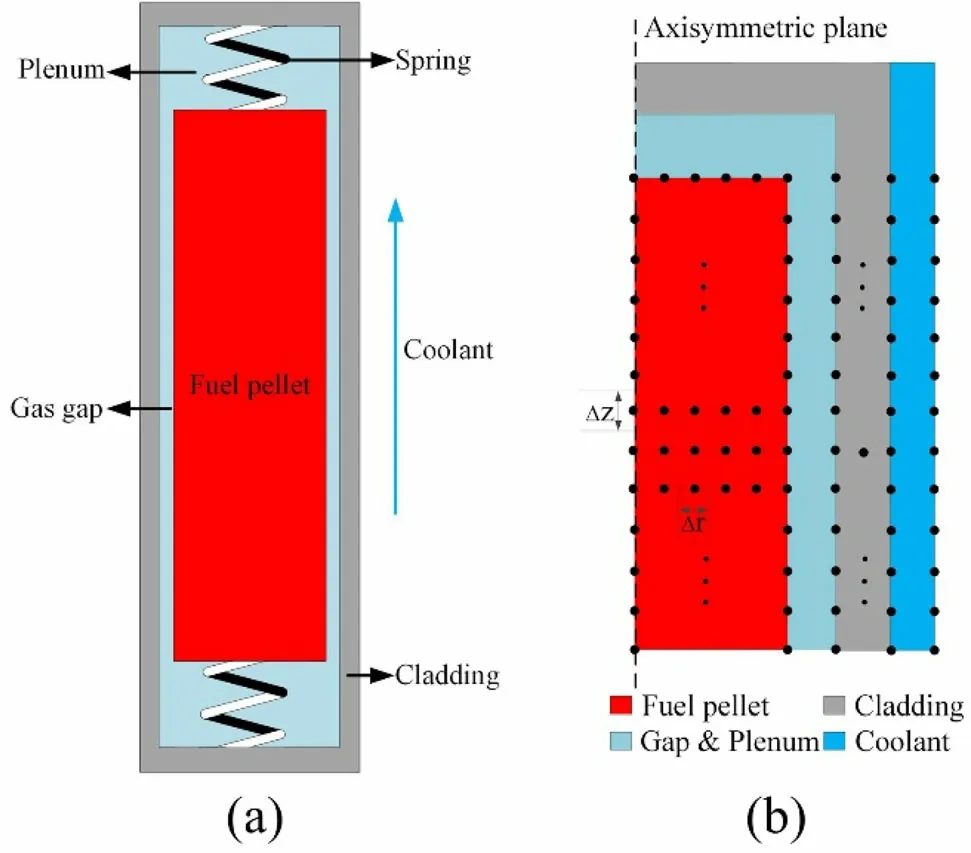
Fig.1 Fuel rod geometry a and nodalization b used by KMC-Fueltra
The main framework of the KMC-Fueltra, shown in Fig. 2, comprises the thermal and mechanical analysis modules, coupled with the irradiation analysis module.Thermal analysis was performed to calculate the temperature of the fuel rod considering the material parameters,operating conditions, and structural parameters. The mechanical analysis was performed to calculate the stress,strain, and deformation of the fuel rod. The irradiation analysis was performed to calculate the fission gas release and irradiation behaviors. Temperature of the fuel rod was transferred to the mechanical and irradiation analysis modules. The changed radius of the pellet or cladding was transferred to the thermal analysis module to remesh the grid.Stress of the fuel rod was transferred to the irradiation analysis module to calculate the fission gas release and irradiation behaviors. Conversely, the gas concentration was transferred to thermal analysis module to calculate the gap conduction, while the plenum pressure and the irradiation behaviors were transferred to mechanical analysis module to calculate the stress–strain distribution.
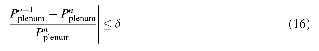
Figure 3 shows the code flow diagram. The entire irradiation period was divided into several steps. The input of steady-state results is optional and depends on whether the simulation is steady state or transient.When the geometry,material type, and operating conditions were determined,thermal, fission gas release, and mechanical analyses were all performed in a time step.After each of these converge,coupling between them starts. Equation 16 gives the convergence criterion for the coupling. The plenum pressure,which is calculated using the ideal gas equation,is selected as the judge parameter because it is the bond of the thermal–mechanical coupling calculation. When the criterion is satisfied, the calculation advances to the next time step and repeats the above process until completion of irradiation time.

Fig. 3 Flow diagram of KMC-Fueltra

Fig. 2 Thermal–mechanical and irradiation coupling scheme
4 Verification and validation
4.1 Modular comparison
The modular validation of KMC-Fueltra focused on thermal and fission gas release analyses. Validation of the mechanical analysis was discussed in a previous study[29].Results from experimental data and analytical solutions were compared with the code results to illustrate the correctness and reliability of KMC-Fueltra.
4.1.1 Thermal analysis
The thermal calculation of fuel rods is the basis of fission gas release and mechanical analyses. Analytical solutions and code results were chosen for comparison with the KMC-Fueltra. It is easy to find an analytical solution for steady-1D heat conduction by integration.For cladding,the inner surface temperature can be calculated using the following equation:
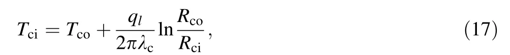

Fig. 4 Comparison results of the fuel rod radial temperature
where qlis the linear power. A constant thermal conductivity is used in Eq. 17 because it is not significantly dependent on the cladding temperature. However, the fuel pellets had the opposite effect. Therefore, the integrated thermal conductivity is used in Eq. 18 to calculate the fuel pellet temperature at center, whereas the outer surface temperature can be obtained using Eq. 19. Figure 4 shows the comparison results when the outer temperature of the cladding is set to 727.2 K and the linear power is set to 25.98 kW/m [30]. The maximum error from the analytical solution was approximately 10 K at the inner surface of the cladding, which was relatively small.
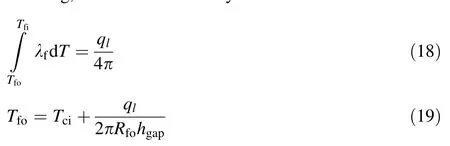
Simulation results from TRAC-AAA,developed by PSI,and EXCURS-M, developed by Japan Atomic Energy Research Institute(JAERI),which are widely used thermal hydraulics codes, were selected for comparison. An assumed beam interruption(BI)accident in an LBE-cooled and MOX-fueled accelerator-driven system has been simulated[30].The axial power profile of the average fuel rod is shown in Fig. 5a.The power factor initially remained at one but dropped suddenly to zero at 1 ms.It later increased gradually at 6 s and then remained almost constant for 19 s.The history of the relative power is shown in Fig. 5b.The specifications of the fuel rod in the Preliminary Design Study of eXperimental Accelerator-Driven Systems (PDSXADS) are listed in Table 1.
Figure 6 shows the changes in the pellet center temperature and coolant outlet temperature. As can be seen from these figures,the temperature of the pellet and coolant changes with power during BI accidents, but the coolant temperature changes slightly later than the power because the process of heat transfer takes time.It can be concluded that the results of the simulations are consistent. These comparison results preliminarily illustrate the correctness of the numerical algorithm used in the thermal analysis,which provides a good foundation for other analysis modules.
4.1.2 Fission gas release analysis
Fission gas release behavior is essential for thermal and mechanical analysis by changing the gap conduction and acting as a boundary condition. The experimental data obtained from JOYO and the simulation results obtained by FEAST-OXIDE were selected to validate the correctness of this module. Experimental fast reactor of Japan, JOYO,was constructed to improve fast reactor safety and test advanced fuels and materials[31].They have different core designs at different times. The MK-I core was critical in 1977, with an initial thermal power of 50 MW, which increased to 75 MW in 1979. The reactor core was then upgraded to MK-II in 1982, and its thermal power was increased to 100 MW. Table 2 lists the fuel rod specifications for cores MK-I and MK-II.
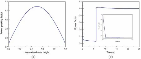
Fig. 5 Axial power profile a and transient relative power b during BI accident
Table 1 Fuel specifications for LBE-cooled PDS-XADS
Figure 7 shows a comparison of the changes in the fission gas release fraction with burnup. It can be observed that the calculation results by KMC-Fueltra during the operation are in good agreement with most of the experimental data obtained from MK-I and MK-II and the calculation results by FEAST-OXIDE. However, there was still a slight difference on some occasions. It was concluded that these two factors could account for these differences. First, the joint oxide gain, which has not been considered in KMC-Fueltra, significantly affects the thermal conductivity of the fuel and results in a high release of fission gases. Second, the amount of fission gas released cannot be directly measured. It is calculated using other directly measured parameters, which means that the data itself have some uncertainties. The results from KMCFueltra agreed well with most of the experimental data within 6 at%burnup.In general,the accuracy of the fission gas release analysis module was valid within this range.
4.2 Integral comparison
The integral validation of KMC-Fueltra was implemented by simulating the fuel rod behaviors of LBE-cooled PDS-XADS using FRED. Parameters such as temperature and radius were calculated considering the influence of multi-physics coupling on the fuel rod performance.
Fast-spectrum advanced systems for power production and resource management (FAST)[32],developed by PSI,is a general analytical code capable of determining the core static and dynamic behavior of advanced fast-spectrum systems for different coolants.Several codes,including the thermal-hydraulics code TRAC/AAA and the thermalmechanics code FRED, were integrated into FAST using a generic method. FRED has been applied to analyze PDSXADS in a wide range of transients to assess the safety of these designs. The specifications for the fuel rod are listed in Table 1.
The fuel rod behavior during the assumed beam power jump (BPJ) accident in the LBE-cooled PDS-XADS was chosen to validate the KMC-Fueltra. This is a good example to evaluate the coupling of thermal–mechanical analysis, considering that the gap was closed during the accident.The axial power profile of the average fuel rod is shown in Fig. 5a.The power increased linearly to six times the nominal value over a 10 s period and then remained constant for 70 s. The history of the relative power considering the negative reactivity feedback of the fuel axial expansion is shown in Fig. 8.

Fig. 6 a Pellet center temperature and b coolant outlet temperature, during BI accident
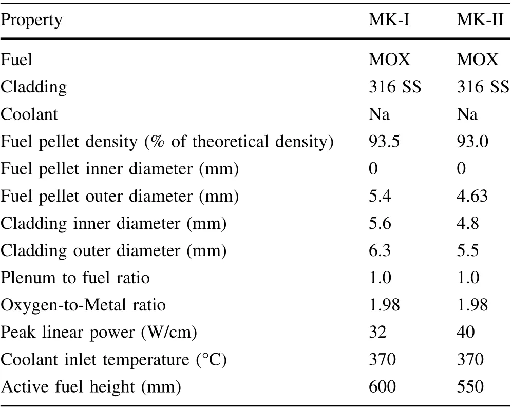
Table 2 Fuel rod specifications for MK-I and MK-II core
Figure 9a shows the peak fuel pellet temperature during the BPJ accident. As can be seen, results calculated by these three codes agree well in the first 10 s,but after this,the results from TRAC/AAA become significantly higher than those from FRED and KMC-Fueltra. It could be explained that the turning point was when PCMI occurred.FRED and KMC-Fueltra consider a contact component in the gap heat conduction, leading to a decrease in the temperature, which is more realistic in the reactor.
Figure 9b shows the change in radius of the fuel pellet and cladding during the BPJ accident. As can be seen, the values of the fuel pellet outer radius and cladding inner radius become larger at the beginning, but later, they change to the same value. It is at this point that PCMI occurred, changing the temperature of the fuel rod, as shown in Fig. 9a. The results of these two codes match well with each other, but are slightly different at the inflection point.The reason is that FRED adopts the‘‘rigid pellet model’’ just like FRPCON and FRPTRAN, which neglects the stress-induced deformation of the fuel. It is considered that fuel deformation is isotropic and rigid,and only some inelastic strains like thermal expansion, swelling, densification, and relocation result in changes in the fuel pellet dimension. Besides these mentioned irradiation behaviors, KMC-Fueltra also considers the influence of cracking, healing, and creep of the fuel pellet in detail.
Thus far, the validation of KMC-Fueltra has been completed. It can be seen that whether it is validated by analytical solutions, experimental data, or simulation results, KMC-Fueltra provided satisfactory prediction results, which can prove the correctness and reliability of KMC-Fueltra in predicting the performance of oxide fuel rods in the LMFR.
5 Conclusion
In this study,a new oxide fuel rod performance analysis code, named KMC-Fueltra, was developed to evaluate the performance of the fuel rod under both normal and transient conditions in the LMFR. The code was validated by results from experiments, codes, and analytical solutions from the module to integration. The following conclusions were drawn:
(1) Based on the equations and models describing the thermal, mechanical, fission gas release, and irradiation behaviors of the oxide fuel rod, corresponding algorithms dealing with them have been established,and KMC-Fueltra was developed with the C language under the modular design concept.
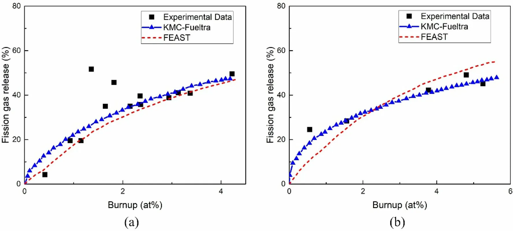
Fig. 7 Fission gas release fraction of JOYO MK-I a and JOYO MK-II b
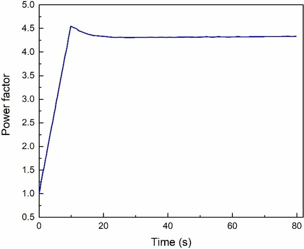
Fig. 8 Transient relative power during BPJ accident
(2) Temperatures of the fuel pellet,cladding and coolant were compared with the analytical solutions and simulation results from TRAC-AAA and EXCURSM. The fission gas release fraction was compared with the experimental data from JOYO and simulation results from FEAST-OXIDE. The temperature and size of the fuel rod during the assumed BPJ accident of the LBE-cooled PDS-XADS were compared with the simulation results from FRED. All comparisons showed good consistency, proving the accuracy and reliability of KMC-Fueltra.
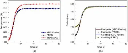
Fig. 9 Fuel pellet peak temperature a and fuel rod radius b during BPJ accident
The validation of KMC-Fueltra was accomplished by comparison with several cases, and these results can be used to preliminarily demonstrate the reliability and accuracy of KMC-Fueltra, which means that the code can be applied to the performance evaluation of oxide fuel rods in LMFR. In the future, the integral results will be validated further once experimental data are available. In addition,mass transfer/chemistry analysis is underway and will be later incorporated into KMC-Fueltra.
Author contributionsAll authors contributed to the study conception and design. Material preparation, data collection and analysis were performed by Guang-Liang Yang,Hai-Long Liao,Tao Ding and Hong-Li Chen. The first draft of the manuscript was written by Guang-Liang Yang and all authors commented on previous versions of the manuscript.All authors read and approved the final manuscript.
杂志排行

Nuclear Science and Techniques的其它文章
- Spatial resolution and image processing for pinhole camera-based X-ray fluorescence imaging: a simulation study
- Picosecond time-resolved X-ray ferromagnetic resonance measurements at Shanghai synchrotron radiation facility
- Nonrecursive residual Monte Carlo method for SN transport discretization error estimation
- Density fluctuations in intermediate-energy heavy-ion collisions
- Isospin effects on intermediate mass fragments at intermediate energy-heavy ion collisions
- Identification of anomalous fast bulk events in a p-type pointcontact germanium detector