Analysis and simulation of the tune ripple effect on beam spill ripple in RF-KO slow extraction
2022-07-26WenBoYeHongJuanYaoShuXinZhengXiaLingGuanXueWuWang
Wen-Bo Ye· Hong-Juan Yao · Shu-Xin Zheng· Xia-Ling Guan ·Xue-Wu Wang
Abstract Tune ripple has a significant influence on beam spill ripple in RF-knockout (RF-KO) slow extraction. In this study, a model was proposed to explain how the tune ripple affects the beam spill in RF-KO slow extraction;consequently,a simulation was performed using the lattice of the Xi’an Proton Application Facility (XiPAF) synchrotron to verify the model. The simulation demonstrates that the tune ripple influences the beam spill in two ways.On the one hand,the tune ripple causes a direct fluctuation in the separatrix area, which induces beam spill ripple. On the other hand, the tune ripple influences the emittance growth rate in RF-knockout slow extraction. These two aspects simultaneously contribute to the beam spill ripple.
Keywords RF-knockout slow extraction · Synchrotron ·Tune ripple · Power supply ripple · Beam spill ripple
1 Introduction
When a spacecraft is in space,it is constantly exposed to a space radiation environment. When high-energy charged particles are incident on the sensitive volume of electronic devices in a spacecraft, the radiation will affect these devices in various ways,which may disturb the logic of the device, affect the device performance, reduce the reliability, and even permanently damage the spacecraft. To ensure a stable operation of the spacecraft in space, it is necessary to study the space radiation effect and construct more radiation-resistant electronic devices.
To study the effects of space radiation, in addition to theoretical analysis and simulation, it is necessary to conduct radiation experiments. Compared with sending electronic devices into space for experiments, acceleratorbased ground radiation environment simulations are more convenient and economical. Based on the fact that protons account for the largest portion of space radiation and cause the most damage, many international laboratories have built accelerators and beamlines for studying proton radiation effects, such as the 230 MeV cyclotron at Indiana University [1] in the USA and Paul Scherrer Institute in Switzerland [2].
The Xi’an Proton Application Facility (XiPAF) is the first Chinese facility dedicated to simulating space radiation environments. It consists of a 7 MeV linac injector, a synchrotron (60–200 MeV), and two experimental stations[3, 4]. According to the requirements of space radiation simulation, the proton accelerator should provide a quasi-DC-extracted beam with an adjustable width from 1 s to longer than 10 s. Third-order resonance extraction is adopted to obtain a long extraction time.The RF-knockout(RF-KO) method [5] is used to feed the excited resonance by exciting the particles transverse emittance growth. The RF-KO method is widely used in the hadron therapy field because of its quick response to beam-on and beam-off applications.Moreover,it can easily control the intensity of the extracted beam.
The extracted beam in the third-order extraction is also referred to as the ‘‘spill’’. The spill uniformity is crucially important in some applications, namely ‘‘fixed target experiments’’[6,7]and hadron therapy[8].The third-order resonant extraction process is sensitive to the horizontal betatron tune because the horizontal betatron tune is close to the third-order resonance. Owing to the sensitive nature of the third-order resonant extraction, the tune ripple has a significant influence on the temporal structure of the beam spill. Tune ripples can induce betatron tune fluctuations,which lead to the temporal modulation of the spill.In other words,the tune ripple is transferred to the beam spill ripple via betatron tune modulation.
Tune ripples mainly originate from the power supply ripple, especially the main dipole and quadrupole power supply. To deal with the power supply ripple, a lot of research and efforts have been made to explain how the power supply ripple transfers to the beam spill ripple and mitigate the power supply ripple influence. Research regarding the transfer function between the quadrupole power supply ripple and beam spill ripple in quadrupoledriven resonance slow extraction has been reported in J-PARC [9] and CERN [6]. The transit time during the slow extraction process has been researched in proton ion medical machine study (PIMMS) [10] and has been utilized to suppress the spill ripple caused by the power supply ripple in GSI SIS-18[7,11].However,these studies are mainly concerned with the power supply ripple in quadrupole-driven slow extraction rather than RF-KO slow extraction.
In third-order slow extraction, the stable triangle separatrix area depends on the horizontal betatron tune distance from the third-order resonance,in addition to the sextupole field strength. Therefore, the betatron tune variation induces a stable separatrix area variation. In quadrupole-driven slow extraction, the stable separatrix area slowly shrinks with time owing to moving the machine tune towards resonance. If there is a tune ripple, the area shrinkage is modulated by the tune ripple; then the spill ripple occurs.However, RF-KO slow extraction is somewhat different from quadrupole-driven slow extraction. In RF-KO slow extraction,the stable separatrix area remains constant and a transverse RF-field is used to excite the particle emittance growth to enter the unstable area. Quadrupole-driven slow extraction has no such emittance growth caused by the RFfield. Naturally, in RF-KO slow extraction, not only the separatrix area but also the emittance growth is affected by the tune ripple. The emittance growth rate in RF-KO slow extraction usually depends on the parameters of the RFfield used to excite particles, in addition to the horizontal betatron tune. Based on the tune ripple effect, the betatron tune fluctuates while the RF-KO parameters remain constant, which induces emittance growth rate variation and finally is transferred to beam spill ripple. The separatrix area and emittance growth rate variations both contribute to spill ripple.However,in a previous study on the tune ripple influence in RF-KO slow extraction[12],only the variation of the stable separatrix area was considered and tune ripple influence on the emittance growth was neglected. In this study,a model is proposed to explain how the tune ripple is transferred to the beam spill ripple in RF-KO slow extraction, which includes both the stable separatrix area and beam emittance growth rate variation.Subsequently,a simulation using the XiPAF synchrotron lattice was performed to verify the model.
2 A previous study on tune ripple effect in RF-KO slow extraction
A model of how the tune ripple transfers to the beam spill ripple in RF-KO slow extraction has been proposed in a previous study by HIMAC [12]. The stable triangle separatrix area A produced by the third-order resonance and sextupole magnetic field is defined as follows:
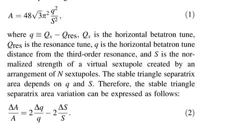
The condition |(Δq/q)/(ΔS/S)|≫1 is usually satisfied because the betatron tune is close to the resonance and q is very small. Hence, the effect of sextupole ripple can be neglected compared with that of the tune ripple.
The beam is extracted at an intensity of I particles per second (PPS) using the RF-knockout slow extraction method; the extracted beam intensity remains constant without the ripple effect. The beam spill ripple is induced by the separatrix area variation through the tune ripple by spilling out the particles near the separatrix. Considering the separatrix area variation,the extracted beam intensity I is expressed as follows:

From Eq. (6), it can be found that the beam spill ripple amplitude induced by the tune ripple is proportional to the tune ripple amplitude a, frequency f, and average particle density near separatrix ρ. However, notice that only the stable triangle separatrix area variation caused by the tune ripple is considered in this model.The emittance growth is not considered. The experimental data [12] for the beam spill ripple amplitude induced by the tune ripple are presented in Fig. 1. Observe that the beam spill ripple amplitude is proportional to the tune ripple amplitude, and the vertical axis intercept is almost zero in Fig. 1a. However,the vertical axis intercept in Fig. 1b is nonzero,which means that the spill ripple is not proportional to the tune ripple frequency. Although there are only two frequencies in Fig. 1b, the nonzero intercept is clear. Moreover, the intercept depends on the tune ripple amplitude, whose value increases with the tune ripple amplitude.This means that the experimental results are inconsistent with the theoretical analysis obtained from the model. The emittance growth rate variation is neglected in this model,which may have caused the difference between theoretical and experimental results.

Fig.1 Experimental data from[12].a Spill ripple amplitude vs.tune ripple amplitude for different tune ripple frequencies and b spill ripple amplitude versus tune ripple frequency for different tune ripple amplitudes
3 A novel beam spill ripple model
We propose a novel model to describe the beam spill ripple, which includes the influence of separatrix area and emittance growth rate variation.
If the particle distributions in x and x′directions follows a Gaussian distribution, the radial distribution function of the particles in the normalized phase space (X,X′) can be expressed using the Rayleigh distribution function as follows [13] :

where θ is the kick angle amplitude of the transverse RFfield and k is a coefficient related to the parameters of the RF-KO and horizontal betatron tune. By choosing a suitable amplitude modulation function θ(n), where dNext/dn remains constant,a flat spill can be achieved.However,if a tune ripple is induced by the power supply ripple,the beam intensity will be affected.
Figure 2 shows the Steinbach diagrams for the RF-KO slow extraction process without and with ripple, respectively. In a Steinbach diagram, the horizontal axis represents the betatron tune of the particles and vertical axis represents the particle radial amplitude in the normalized phase space. The separatrix divides the normalized phase space into two regions: a stable and an unstable area. The particles in the stable area are excited by a transverse RFfield; then, these particles’ emittance growths enter the unstable area. If there is no tune ripple, the separatrix area and emittance growth rate are both constant. However,both the separatrix area and emittance growth rate fluctuate if a tune ripple exists. The separatrix area and emittance growth variation affect the beam spill.
First,we consider the influence of the tune ripple on the stable triangle separatrix area.r0is the equivalent radius of a circle with the same area as the stable triangle. In other words,πr20is equal to the separatrix area A0.With the tune ripple effect,the separatrix area is no longer a constant and can be expressed as:
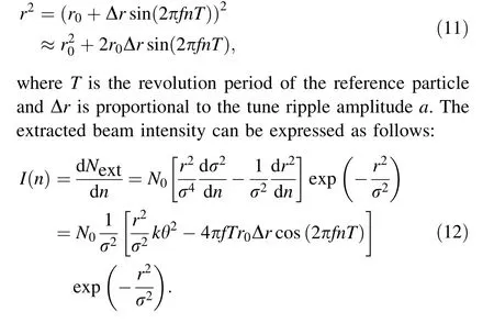
The first term on the right side of Eq. (12) can be considered a constant, while the second cosine term denotes the spill ripple induced by separatrix area fluctuation. Because Δr ∝a, the spill ripple amplitude is proportional to the tune ripple amplitude and frequency. This conclusion agrees with Eq. (6) taken from the previous model.
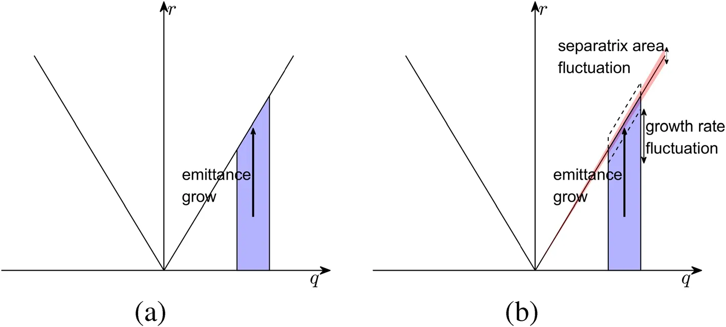
Fig.2 Steinbach diagram of the RF-KO slow extraction a without tune ripple influence and both a constant separatrix area and emittance growth rate;b with tune ripple influence and both a fluctuating (timevarying) separatrix area and emittance growth rate
Then, we consider the influence of the tune ripple on emittance growth. In RF-KO slow extraction, to excite all particles effectively, the transverse RF-field should have a frequency bandwidth Δf that covers the betatron tune spread. In general, the center frequency and bandwidth of RF-KO are chosen to cover the tune spread.The coefficient k mentioned in Eq. (10) represents the emittance growth rate. The larger the value of k is, the faster the emittance increases.The coefficient k is related to the beta function β,center frequency of RF-KO, bandwidth of RF-KO, and betatron tune [13]. Here, k is proportional to β and 1/Δf.The variation in β caused by tune variation is quite small,which is not the main reason for the variation in k.In fact,the change in Δf is the main reason for this.When the tune varies, the tune spread also changes. However, the center frequency and bandwidth of RF-KO remains constant.The parameters of RF-KO do not match the betatron tune and tune spread.In other words,the effective bandwidth of RFKO varies as well.Thus,the emittance growth rate,that is,the coefficient k, varies. If the variation is small, considering the first-order approximation, k can be expressed as follows:

where Kqis the coefficient of the first-order approximation,k0represents the emittance growth rate or RF-KO excitation efficiency without the ripple effect, and Δk ≡Kqa denotes the variation of k,which is proportional to the tune ripple amplitude a. Note that Eq. (13) requires that the repetition frequency of FM (frequency modulation) is much larger than the tune ripple frequency.k is the average emittance growth rate in an FM period. The higher the repetition frequency of FM is,the shorter is the FM period.A shorter FM period means that the emittance growth is modulated by the tune ripple more clearly.If the repetition frequency of FM is smaller than the tune ripple frequency,the FM period is longer than that of the tune ripple, which means that in an FM period, the betatron tune variation averaged over time is extremely small.Thus,the emittance growth rate modulation by the tune ripple is weak and Eq. (13) may no longer hold.
After considering the emittance growth rate variation,the beam intensity can be expressed as follows:
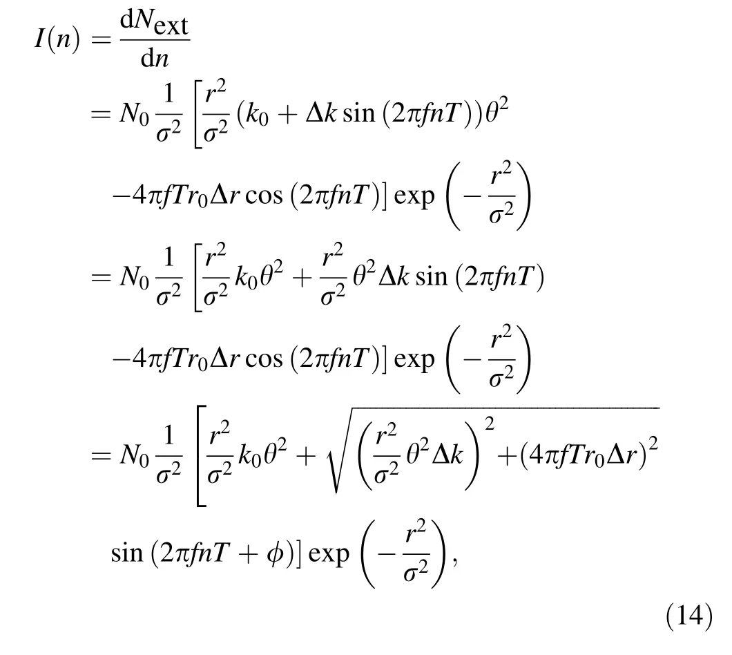

There are two terms regarding the beam spill ripple in Eq. (14).As mentioned previously,the cosine term denotes the spill ripple caused by the stable triangle separatrix area variation, whose amplitude is proportional to the tune ripple amplitude and frequency. The sine term represents the spill ripple induced by emittance growth rate variation,whose amplitude depends only on the tune ripple amplitude. If the tune ripple frequency f approaches zero, then the amplitude of the cosine term also approaches zero.However,the amplitude of the sine term remains the same,which causes a nonzero intercept as depicted in Fig. 1b1.Note that certain parameters mentioned in Eq. (14),namely k0and Δk, are difficult to determine theoretically, and σ2and θ are time-dependent. Thus, Eq. (14) is suitable only for qualitative analysis.It is almost impossible to calculate the real spill ripple using Eq. (14).
Furthermore, the cosine and sine terms can be summed as a sine term as shown in Eq. (14). Because both Δr and Δk are proportional to the tune ripple amplitude a, the relationship between the beam spill ripple and tune ripple amplitudes and frequency can be expressed as follows:
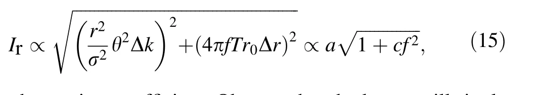
where c is a coefficient. Observe that the beam spill ripple amplitude has a linear dependence on the tune ripple amplitude and nonlinear dependence on the tune ripple frequency.
4 Simulation method and results
4.1 Simulation method
The amplitude and frequency dependence of the beam spill ripple amplitude derived from the model were verified via a simulation. To simulate the slow extraction process more conveniently and quickly, a high-performance code Li-Track based on C++ was developed for the beam dynamics simulation of a synchrotron [14, 15]. The Li-Track code is a parallel multiparticle tracking program written entirely in C++, thus, can achieve a high computational speed. The overall design of the Li-Track follows the object-oriented programming principles. The implemented element model can be easily reused to build different synchrotron lattices.A symplectic integral algorithm is used to ensure that there are no physical errors in the long-term simulation.The lattice of the XiPAF synchrotron was used for the simulation.The dual FM method[16]and amplitude modulation (AM) [13] were applied. Table 1 lists the main parameters used in the simulations.
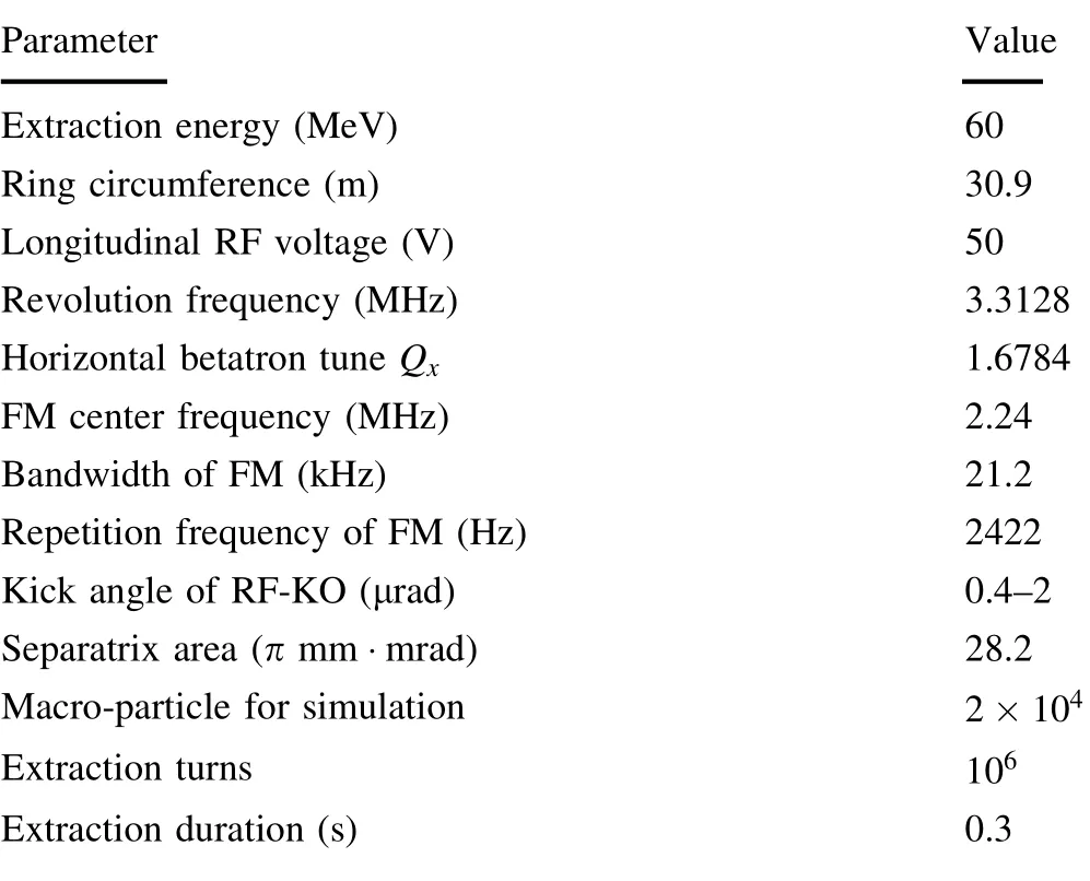
Table 1 Basic simulation parameters

Fig. 3 Simulation results of the extracted beam spill under different power supply ripple amplitudes: a QF power supply ripple is a sine waveform with a frequency of 50 Hz and amplitude of 100 ppm.b QF power supply ripple is a sine waveform with a frequency of50 Hz and amplitude of 250 ppm
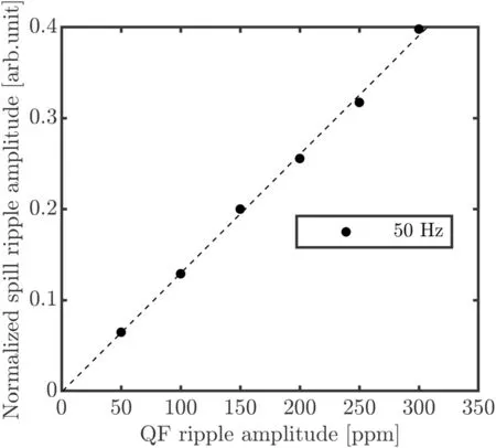
Fig.4 Correlation between the average normalized beam spill ripple and QF power supply ripple amplitudes. The dashed line is the curve fitted using a linear fit, and the dots represent the data obtained from the simulation results. The linear dependence can be observed; the intercept of the vertical axis is almost zero
The tune ripple mainly originates from the power supply ripple. The main dipole and quadrupole power supply ripples cause the tune ripple. In this simulation, the tune ripple was introduced by the quadrupole power supply ripple. Only the focusing quadrupole (QF) power supply ripple was considered because the defocusing quadrupole has a small influence on the horizontal betatron tune compared with the focusing quadrupole. The relationship between the tune ripple amplitude a and QF power supply ripple in XiPAF synchrotron can be expressed as follows:
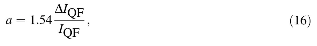
where ΔIQF/IQF denotes the amplitude of QF power supply ripple.Without loss of generality,QF power supply ripple is assumed to be a sine wave with an initial phase equal to zero.The extraction duration in the simulation was 0.3 s, which was sufficiently long compared to the power supply ripple period. Although the beam spill ripple amplitude may change over time, the average beam spill ripple amplitude can be obtained from the frequency spectrum of the beam spill using the fast Fourier transform(FFT) method. To compare the simulation results more conveniently, the beam spill ripple amplitude was normalized by the average extracted beam intensity.
4.2 Influence of the power supply ripple amplitude
To measure the correlation between the beam spill ripple and QF ripple amplitudes, we fixed the QF ripple frequency at 50 Hz and varied the amplitude from 50 ppm(parts per million) to 300 ppm. Figure 3 shows the time structure of the spill under different QF ripple amplitudes.The beam intensity fluctuates significantly as the QF ripple amplitude increases.
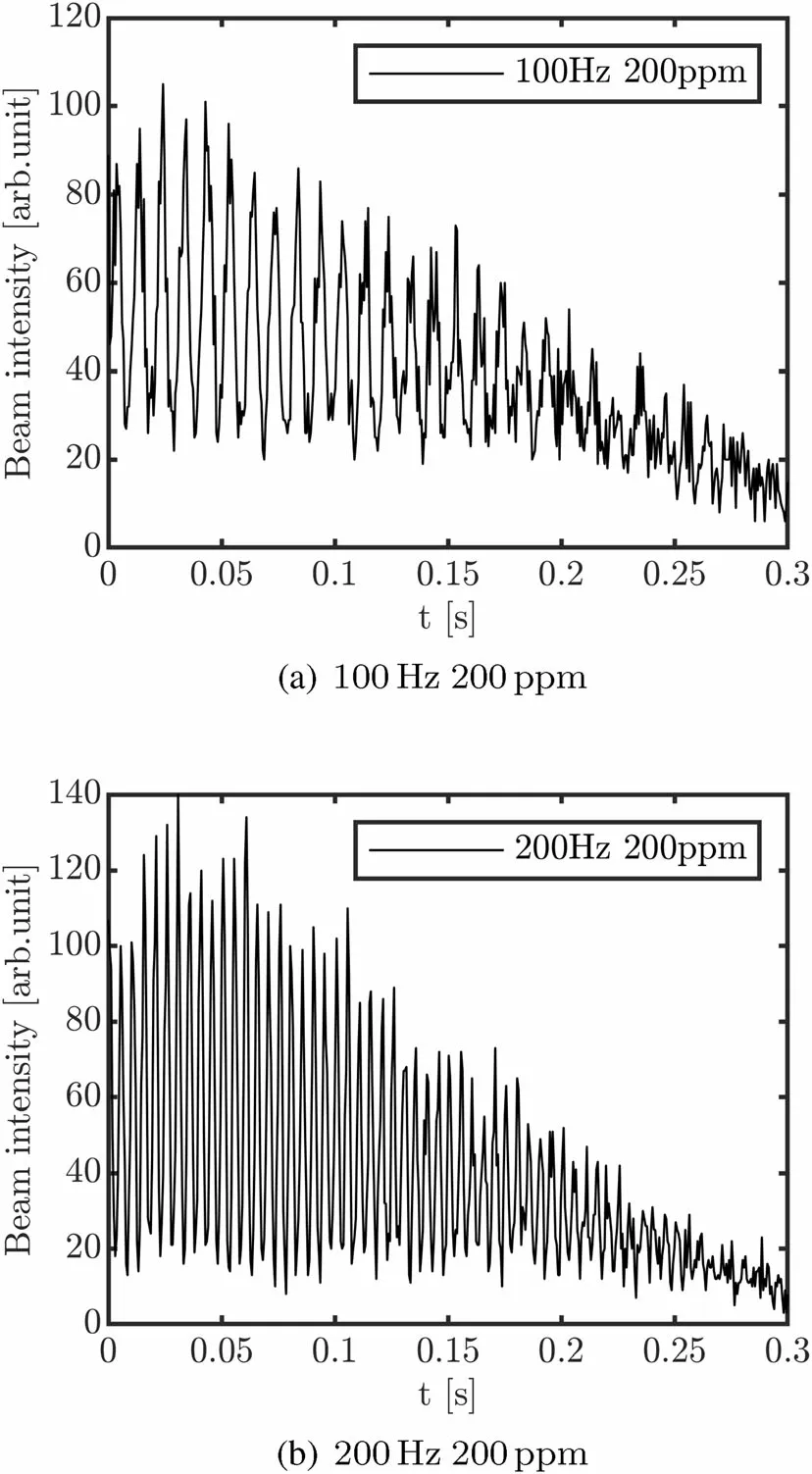
Fig. 5 Simulation results of the extracted beam spill under different power supply ripple frequencies: a QF power supply ripple is a sine waveform with a frequency of 100 Hz and amplitude of 200 ppm.b QF power supply ripple is a sine waveform with a frequency of 200 Hz and amplitude of 200 ppm
Although the beam spill ripple amplitude is time dependent,the average amplitude can be obtained by FFT.The correlation between the average normalized beam spill ripple and QF ripple amplitudes is depicted in Fig. 4.Observe from Fig. 4 that the average normalized beam spill ripple amplitude linearly depends on the QF ripple amplitude and the intercept of the vertical axis is almost zero,which agrees well with the theoretical analysis results.
4.3 Influence of the power supply ripple frequency

Fig.6 Correlation between the average normalized beam spill ripple amplitude and QF power supply ripple frequency. The dashed lines represent the curves fitted using Eq. (17).The diamonds,squares,and dots represent the data obtained from the simulation results with QF power supply ripple amplitudes of 100 ppm,150 ppm,and 200 ppm,respectively. A nonlinear dependence can be observed, and the intercept of the vertical axis is nonzero
To measure the correlation between the beam spill ripple amplitude and QF ripple frequency, QF ripple amplitude was kept constant while the frequency was varied from 25 Hz to 250 Hz. In this simulation, the QF ripple amplitude was fixed at three values, namely 100 ppm,150 ppm, and 200 ppm. Figure 5 shows the time structure of the spill under different QF ripple frequencies.The extracted beam intensity fluctuates significantly as the QF ripple frequency increases.
From Eq. (15), the relationship between the average normalized beam spill ripple amplitude Inr and QF power supply ripple frequency can be deduced as follows:
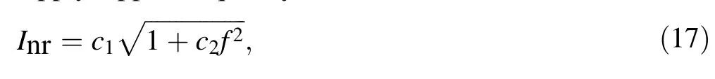
where c1and c2are the fitting coefficients. According to Eq. (15),c1is proportional to QF ripple amplitude whereas c2is independent of QF ripple amplitude. The correlation between the average normalized beam spill ripple amplitude and QF ripple frequency obtained via the simulation is presented in Fig. 6. The dashed lines in Fig. 6 are the curves fitted using Eq. (17). Observe that the relationship between the average normalized spill ripple amplitude and QF ripple frequency is nonlinear.
Coefficients c1and c2can be derived by fitting the simulation data. The QF ripple amplitudes were set to 100 ppm, 150 ppm, and 200 ppm in the simulations. The values of c1are 0.0882, 0.1373, and 0.1854, respectively,and the values of c2are 4.5e-4, 4.1e-4, and 4.1e-4,respectively, with each amplitude value. c1is approximately proportional to the QF ripple amplitude,whereas c2is independent of QF ripple amplitude. In other words, the relationship between the fitting coefficients c1, c2, and QF ripple approximately agrees with the theoretical analysis results obtained from the model.
Furthermore, we compared the fluctuation effect of the separatrix area with that of the emittance growth rate obtained from the simulation results.The nonzero intercept of the vertical axis results from emittance growth rate fluctuation. According to the fitted curves presented in Fig. 6, the intercepts were 0.0882, 0.1373, and 0.1854,respectively, for the three conditions. For the low-frequency QF ripple, taking 50 Hz as an example, the normalized spill ripple amplitudes were 0.1262, 0.1928, and 0.2486,respectively.This implies that in the low-frequency regime (<50 Hz), the spill ripple is mainly determined by the emittance growth rate fluctuation effect. In the highfrequency regime(>100 Hz),fluctuation in the separatrix area is dominant. Note that this conclusion may not be established for all situations because the emittance growth rate variation depends on the parameters of the RF-KO.Different RF-KO parameters cause different spill ripples.
4.4 Emittance fluctuation
The simulation program Li-Track can output the phase space distribution of particles at a fixed frequency. Thus,the circulating beam evolution in the phase space can be obtained during the RF-KO slow extraction process. Figures 7 and 8 demonstrate the circulating beam evolution in the normalized phase space in one QF ripple period. The frequency of QF ripple is 50 Hz; therefore, its period is 20 ms. The subgraph in Figs. 7 and 8 correspond to the normalized phase space at different moments.In Fig. 7,the amplitude of the QF ripple is zero and there is no ripple effect. In Fig. 8, the frequency of the QF ripple is 50 Hz and amplitude is 200 ppm. Compared with Fig. 7, the evolution in the normalized phase space depicted in Fig. 8 is different owing to the QF ripple effect. This indicates that the QF ripple influences not only the separatrix area but also the emittance growth. In RF-KO slow extraction,there are two tune regions: the extraction region near the boundary of the separatrix and diffusion region deep inside the separatrix [16]. Because of the emittance growth caused by RF-KO, the particles in the diffusion region are diffused into the extraction region and then extracted from the extraction region. The extracted beam intensity is determined by the particle density near the separatrix (i.e.,the extraction region) and extraction rate from the extraction region to the unstable area. Because the QF ripple affects the emittance growth,the diffusion rate from the diffusion region to the extraction region and extraction rate from the extraction region to the unstable area change.Both the particle density in the extraction region and extraction rate vary, both of which contribute to the beam spill ripple.
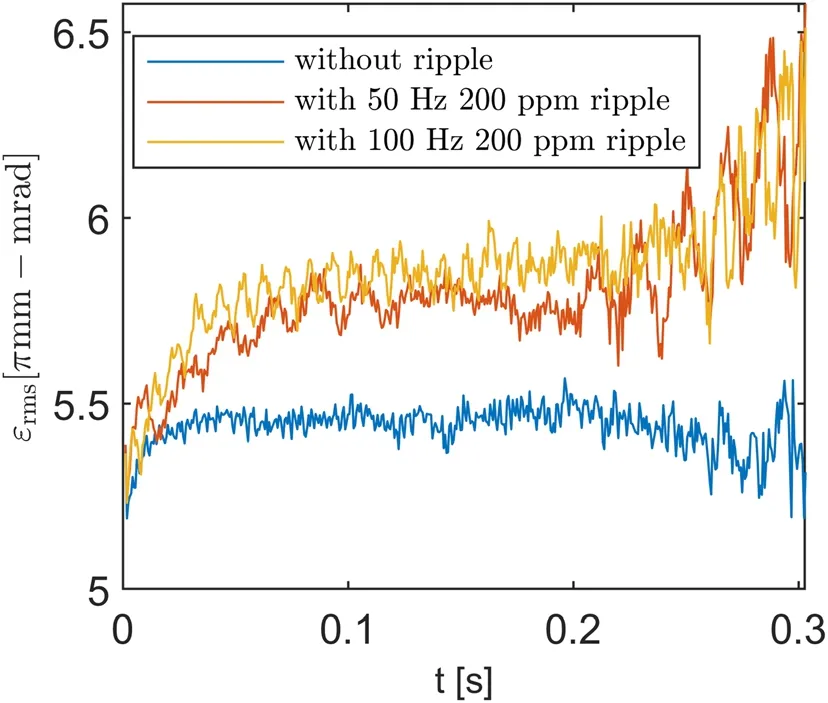
Fig. 9 RMS emittance versus time under different conditions
We calculated the change in emittance with respect to time to directly observe the circulating beam evolution in phase space. To exclude the influence of separatrix area fluctuation, particles near the separatrix were not included when calculating the RMS emittance. Only particles with emittances smaller than 25 π mm·mrad were considered.The separatrix area was 28.2 π mm·mrad without a ripple effect, which could be shrunk to 26.7 π mm·mrad with a 200 ppm QF ripple. Therefore, the 25 π mm·mrad was sufficiently small to exclude the influence of separatrix area fluctuation. The RMS emittance varied over time under different conditions as shown in Fig. 9. The RMS emittance was effectively modulated by the QF ripple compared to the no-power-supply ripple case, which agrees with the theoretical analysis.As mentioned previously, the emittance growth rate depends on the parameters of RFKO; consequently, it is possible to adjust the RF-KO parameters to reduce the emittance growth rate fluctuation.
5 Discussion
The beam spill ripple originates from two phenomena:the stable triangle separatrix fluctuation and emittance growth rate fluctuation. Therefore, we can mitigate the influence of the tune ripple considering two perspectives.The first is to reduce the separatrix area fluctuation influence; for example, by enlarging the betatron tune distance and sextupole field strength simultaneously while keeping the separatrix area constant [12] or lowering the particle density near the separatrix by an extra transverse RF-field[17]. Another is to reduce the emittance growth rate sensitivity to tune ripple,which requires determining adequate RF-KO parameters. As mentioned in Sect. 3,a shorter FM period means that the emittance growth is modulated by the tune ripple more clearly.Hence,appropriately reducing the repetition frequency and lengthening the FM period is a possible way to mitigate the power supply influence. The effects of other parameters, such as the center frequency and bandwidth of the RF-KO, still need to be researched.Further study is needed to realize the mitigation tune ripple influence from the emittance growth perspective.
6 Conclusion
The tune ripple significantly affects the beam spill ripple in RF-KO slow extraction.A novel beam spill-ripple model is proposed in this study. On the one hand, the tune ripple causes the separatrix area fluctuation; on the other hand, it influences the emittance growth rate in the RF-KO extraction method. These two aspects simultaneously contribute to the beam spill ripple. To verify this model, a simulation was performed using the XiPAF synchrotron lattice.The simulation results agreed well with those of the theoretical analysis. Further studies are still needed to mitigate the tune ripple influence to a greater extent.
AcknowledgementsThe authors would like to express their gratitude to Dr. Kota Mizushima for his useful advice and allowing us to use his experimental data in this study.
Author ContributionsAll authors contributed to the study conception and design. Material preparation, data collection, and analysis were performed by Wen-Bo Ye.The first draft of the manuscript was written by Wen-Bo Ye and all authors commented on previous versions of the manuscript. All authors read and approved the final manuscript.
杂志排行

Nuclear Science and Techniques的其它文章
- Spatial resolution and image processing for pinhole camera-based X-ray fluorescence imaging: a simulation study
- Picosecond time-resolved X-ray ferromagnetic resonance measurements at Shanghai synchrotron radiation facility
- Nonrecursive residual Monte Carlo method for SN transport discretization error estimation
- Density fluctuations in intermediate-energy heavy-ion collisions
- Isospin effects on intermediate mass fragments at intermediate energy-heavy ion collisions
- Identification of anomalous fast bulk events in a p-type pointcontact germanium detector